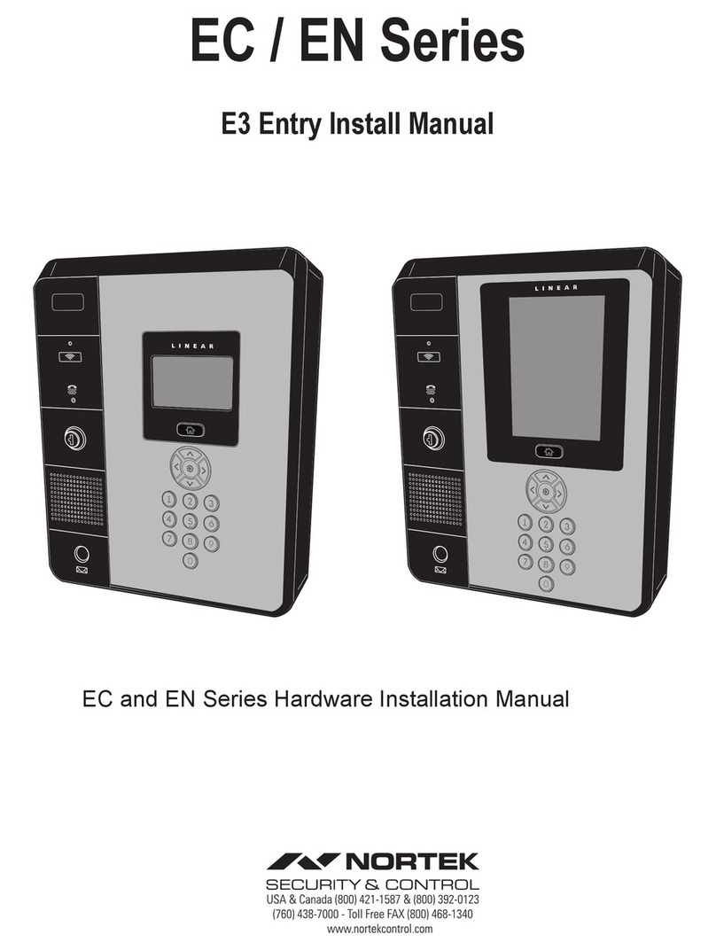
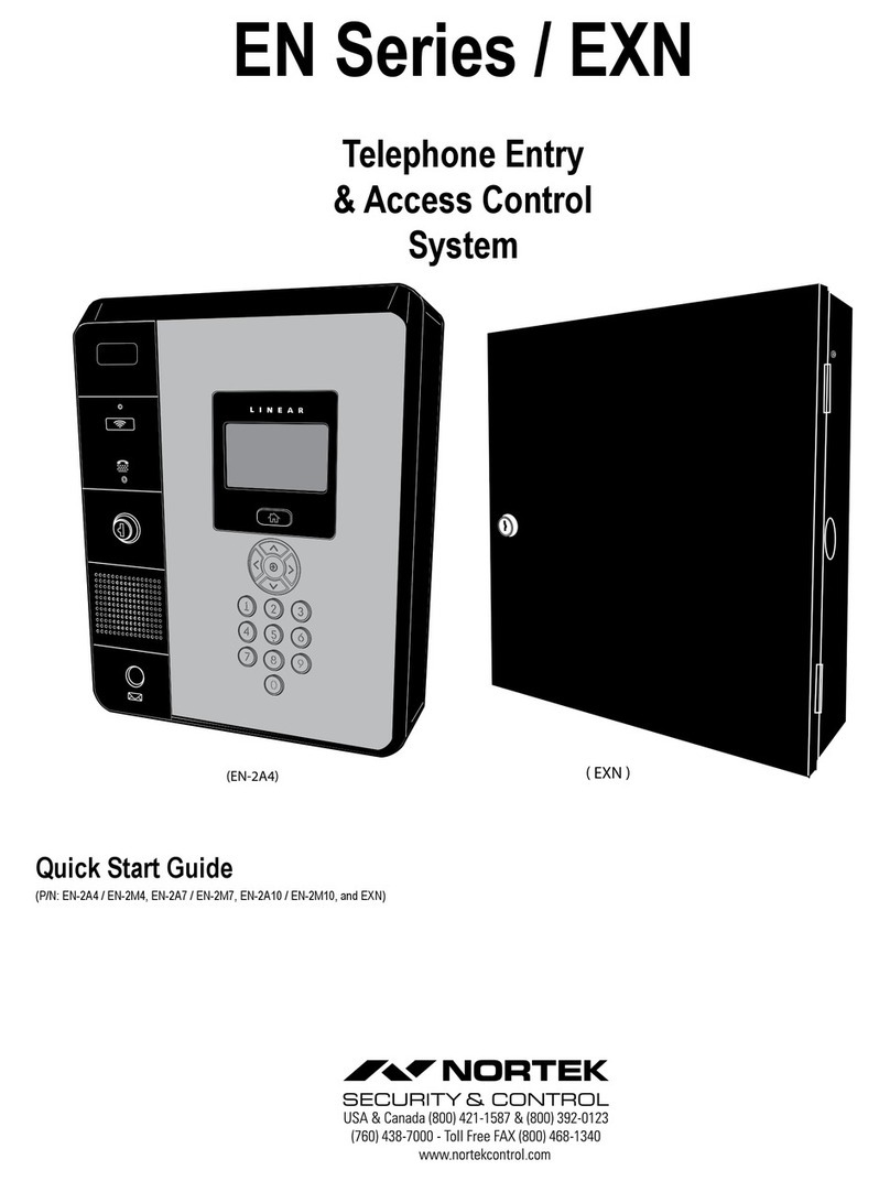
Nortek EP-402 User manual

Quick Start Guide
Telephone Entry & Access Control System
Quick Start Guide
(EP-736)
(EP-402 / EP-436)
or dial
( EP-EXN )

2
IP Address Conguration
NOTE: This Quick start guide is applicable to Entry Pro (EP) Series Telephone Entry system. The thumbdrive in the hardware bag contains additional
installation and wiring instructions.
WARNING: Do Not connect an Ethernet cable from the EP CPU to the Local Area Network (LAN) before the Initial IP System Conguration has been
completed.
The e3 Entry Pro and Access Control system can be a standalone system or part of a larger multi-unit Access Control network. Regardless of the type
of installation the initial IP conguration of the EP is done between a Laptop/PC and the EP unit directly connected to each other not part of the local
network.
IMPORTANT COMPATIBILITY NOTE: The legacy Linear access control Models AE-1000, AE1000Plus, AE-2000, AE2000Plus, AM3, and AM3Plus
are of a different hardware and software design and do not integrate with the new generation networked models.
LAN
PORT
COMPUTER’S
LAN PORT
COMPUTER
FOR CONFIGURING
NETWORK SETTINGS
CPU
BOARD
Network Cable
NOTE: It is recommended that the Telephone Entry System have a static IP Address assigned, not a DNCP assigned
address.
Consult the appropriate on-site IT administrator to obtain the following information before conguring the EP system:
•• IP address:____________________________________
•• Subnet Mask:__________________________________
•• Gateway: _____________________________________
•• DNS 1: _______________________________________
•• DNS 2: _______________________________________
Congure IP Network Settings
To allow for the system to be recognized on the local network, it is necessary to change the unit’s default IP address as follows:
1. Connect your programming computer directly to the LAN port of the EP-xxx unit. A standard CAT5 or better networking cable is used for the
direct connection.
2. Assign a static IP address of 192.168.0.149 to the computer. (For instructions on how to change the static IP address of a Windows computer,
please visit: http://technet.microsoft.com/en-us/library/ff710457
3. After assigning the static IP address to the computer, open a web browser and enter the
default IP address of the unit (Default = 192.168.0.250).
4. The unit presents the login page.
NOTE: It is highly recommended to change the default Password.
To log on, enter the default User ID and Password:
User ID: admin
Password: admin

3
RJ45 LAN
PORT
CPU
BOARD
123456
Ethernet Switch
ROUTER
FIREWALL
INTERNET
Network Cable
Network Cable
5. Select the Network Setting icon, then the IP Address icon to display the IP settings page.
8. Connect the networking cable from the Local Area Network to the unit’s LAN port. The local computers will then be able to access the system
by entering the new static IP address of the unit.
Enter the static IP address, Subnet Mask, Gateway and DNS server so that it matches the requirements of the local network provided by the IT
administrator.
6. Click Save & Reboot for the settings to save and take effect. (The reboot will take approximately 2 minutes.)
NOTE: The IP settings will be lost if the unit is powered down without performing Save & Reboot.
7. Disconnect the programming computer from the unit. The system is now ready for connection to the local network.
CAUTION: The EP is an Access Control system and should be on an isolated or segmented Security network where a protected network
security appliance (rewall, etc.) is installed and maintained. This will help prevent unwanted access from the shared company network
environment.

4
EP-436
Controller
Client
Client
Client
Client
EP-436
EP-EXN
EP-736
Ethernet Switch
EP-EXN
To Router/Firewall
Multi-Unit Installation - Telephone Entry
Below is an example of a multi-unit installation displaying multiple EP and EXN units:

5
Adding additional hardware to build a system with multiple
interconnected units - one database (EP Series Only)
NOTE: Standalone installations proceed to pg. 6 to add users.
EP-x36 Series units provide the ability to add additional controllers to expand the amount of doors, inputs and outputs. These additional controllers are
referred to as clients. An IP Installer is a utility located on a thumb drive shipped with all systems. This utility provides a simple method of identifying
the IP address of the controller(s).
1. Connect all controllers to the local network.
2. Connect a thumb drive to a Windows computer on the local network.
3. Locate IPInstaller.exe and double-click the le.
4. IP Installer will open. Click Scan to search the network for controllers.
5. When controllers are identied they will be listed in IP Installer.
Conguring the Server and Client
The default IP address of the server and client is 192.168.0.250. To avoid conict on the network, the IP address of the client and server must be
changed as follows:
1. Connect the server to the network.
2. Open IPInstaller.exe and click Scan.
3. Select the client from the list and click Set Network.
4. Enter a new IP address for the server. This information must be provided by the IT Administrator.
5. Change the Subnet Mask and Gateway to meet the requirements of the local network. This information must be provided by the IT
Administrator.
6. Enter the IP Installer password (default = 4321) and click OK.
7. Connect the client to the network and repeat steps 1 through 4 to change the client’s IP address.

6
Controller to Client Conversion
This section is for systems that contain multiple TE front ends on the same network.
By default each TE front end is congured as a controller. When multiple TE front ends are in the same network, only ONE can be the controller. All
others must be clients.
This step will need to be performed on all TE units that will NOT be the controller on the network. All EP-EXN’s are pre-congured as clients and do
not need to go through this step.
Note: All TE controllers and clients must be operating on the same software revision. System failure may occur if not updated to the same software revision. Refer to Nortek
Security and Control technical support for assistance in determining and/or updating the software revision.
1. Locate the panels MAC address.
Option 1: Locate on the control board and of the unit you are converting to a client. On the main PC board document the unit MAC address.
Option 2: Retrieve the MAC from the panel license page.
2. Log onto www.e3upgrade.com.
3. Click the License Now button.
4. Enter the last six (6) characters of the system MAC
address.
5. Click Next.

7
Controller to Client Conversion (continued)
6. Locate the license client key sheet document contained in the manual and hardware packet.
The system now will provide a new license key. When this key is applied to license the panel will convert from a server role to a client role
7. Copy this key so it can be pasted into the license screen.
8. Enter information into the correct elds.
9. Click Next.
10. Apply power to TE Display unit.
11. Log into the controller and verify what version system software is running.
12. Log into your system and verify software revisions are identical.
If the software versions are not the same, proceed to the System Settings > Update tab to update units to the same revision.
Default IP address: 192.168.0.250 (admin/admin).
13. Click on the Green Key on the bottom of the page to validate software version and change the license key.

8
Controller to Client Conversion (continued)
14. The license page provides Software Version, MAC Address and Edit button to change the license key.
15. Click on the Edit button, and paste the new license.
16. Click Save.
NOTE: The TE Front End is now a client which can be added to the EP Models as an expansion Module. The license screen will now say TE Client.
17. For instructions on how to add a client, refer to the Programming Manual.

9
Adding Users
Specic information must be input into the system to establish basic
user prole. An access level must be created before a new User can
be created. An asterisk (*) denotes required information.
Perform the following steps to create a new user prole.
1. On the main navigation menu, click New User button.
The Resident data entry elds will appear.
2. Input relevant data into data entry boxes provided under
the Personal section.
NOTE: The Phone Number eld MUST be lled out with a
valid phone number in order for the system to provide voice-
to-voice connection with incoming calls.
3. In the Card Enrollment data entry section, Input
relevant data into data entry boxes.
4. The Card Number data entry line information can be
input manually, or the card can be scanned.
5. In the Access Level section, assign the Type and
Level appropriate for user prole.
6. When all data is entered, Click Save.
Add a Card
Individual cards must be entered into the system.
1. Click the Add Card button.
2. Input data into data entry boxes provided.
3. Ensure the Directory Listed check box is checked.
4. Enter a unique Entry Code. The system will notify
user if entered code is not valid.
5. In the Entry Code section, input a unique entry code.
6. Select an appropriate security Access Level.
7. Click Save.
Repeat process for additional new users.

10
EP Unit Operation
Requesting Access with an Entry Code
• Residents have up to 40 seconds to key in their entry code.
• Up to eight seconds are allowed between each keystroke.
• All digits of the entry code must be entered. Example: If the entry
code length is set for four digits, and the code is 0042, the user
must enter “0 0 4 2”.
• If the wrong key is pressed, pressing the key will reset the
keypad. The correct code can then be entered.
• After a correct code is entered, and if the conditions for granting
access are fullled, the programmed relay will activate for the
programmed time.
• If the number of incorrect codes entered exceeds the keypad
lockout count, the keypad will be locked and not accept any entries
for one minute. This is congurable within the front panel admin
settings.
• If the Anti-passback feature is enabled, the entry code will be
unusable until the anti-passback time expires.
Requesting Access with a Wireless Transmitter
• Activate a wireless transmitter within radio range of the unit’s
antenna.
• When the transmitter key is pressed, the decoded number is
processed like a traditional card or code.
• After a valid transmitter is decoded, and if the conditions for
granting access are fullled, the programmed relay channel will
activate for the programmed time.
• If the Anti-passback feature is enabled, the transmitter will be
unusable until the anti-passback time expires.
Requesting Access with a Visitor Call
• Navigate to Resident Directory using Navigation keys.
• Scroll through the alphabet to the rst letter of the last name.
• Press Enter.
• Scroll through name list to desired entry.
• Press Enter to call.
• If the visitor already knows the resident’s directory number, they
can enter the directory number to call the resident.
• The system dials the resident’s telephone number to establish
2-way communications.
NOTE: The resident’s telephone number will never be displayed to the visitor.
• If the resident is using the telephone at the same time a visitor
calls, the display will indicate to the visitor that the line is busy.
• The resident answers the call and converses with the visitor to
determine if access will be granted.
• The resident can use their telephone’s keypad to grant access
activating Relay Channel “A” by pressing . After access is
granted, the system will disconnect the call.
• The resident can disconnect the visitor without granting access by
pressing or by hanging up.
• The length of time the visitor is allowed to talk can be programmed
from 30-300 seconds.
ENTRY CODE AT LOCAL KEYPAD
3
AFTER
SCROLLING, ENTER
THE RESIDENT
DIRECTORY
NUMBER AND TALK
WITH RESIDENT
ENTER RESIDENT
NUMBER OR SCROLL
THROUGH TO
RESIDENT’S NAME
2
VISITOR
1
USE NAVIGATION
KEYS TO SCROLL
TO DIRECTORY

11
Copyright © 2019 Nortek Security & Control LLC 10027495 B
Limited Warranty
This Nortek Security & Control LLC product is warranted against defects in material and workmanship for twenty-four (24) months. This warranty
extends only to wholesale customers who buy direct from Nortek or through Nortek’s normal distribution channels. Nortek Security & Control LLC
does not warrant this product to consumers. Consumers should inquire from their selling dealer as to the nature of the dealer’s warranty, if any.
There are no obligations or liabilities on the part of Nortek Security & Control LLC for consequential damages arising out of or in connection with use or
performance of this product or other indirect damages with respect to loss of property, revenue, or prot, or cost of removal, installation, or reinstallation.
All implied warranties, including implied warranties for merchantability and implied warranties for tness, are valid only until the warranty expires. This
Nortek Security & Control LLC Warranty is in lieu of all other warranties express or implied.
All products returned for warranty service require a Return Authorization Number (RA#). Contact Nortek Security & Control Returns at 1-855-546-3351
for an RA# and other important details.
FCC Notice
Changes or modications not expressly described in this manual or approved by the manufacturer could void the user’s authority to operate the
equipment.
This equipment has been tested and found to comply with the limits for a Class B digital device, pursuant to Part 15 of the FCC Rules. These limits are
designed to provide reasonable protection against harmful interference in a residential installation. This equipment generates, uses and can radiate
radio frequency energy and, if not installed and used in accordance with the instructions, may cause harmful interference to radio communications.
However, there is no guarantee that interference will not occur in a particular installation. If this equipment does cause harmful interference to radio or
television reception, which can be determined by turning the equipment off and on, the user is encouraged to try to correct the interference by one or
more of the following measures:
• Reorient or relocate the receiving antenna.
• Increase the separation between the equipment and receiver.
• Connect the equipment into an outlet on a circuit different from that to which the receiver is connected.
• Consult the dealer or an experienced radio/TV technician for help.
For Technical Assistance contact Nortek Security & Control at (800)-421-1587 or (760)-438-7000

12
Page left intentionally blank
This manual suits for next models
3
Table of contents
Other Nortek Intercom System manuals