ix
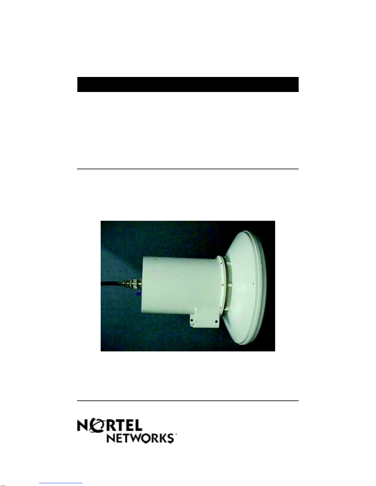
Reunion CTR 38 Ghz Installation Guide
Documentation Suite
This Reunion Release has a suite of fifteen documents:
Reunion System Overview, 411- 1343 - 010
Reunion Network Node Equipment Installation Guide, 411- 1313 - 200
Reunion NIU 6054 Network Interface Unit Installation Guide,
Release 1.2, 411- 1323 - 201
Reunion NIU 6154 Network Interface Unit Installation Guide,
Release 1.2, 411- 1323 - 202
Reunion NIU 5008 Network Interface Unit Installation Guide,
Release 1.2, 411- 1323 - 203
Reunion BTR 28 GHz Outdoor Microwave Transceiver Installation Guide,
Release 1.2, 411- 1333 - 202
Reunion CTR 28 GHz Outdoor Microwave Transceiver Installation Guide,
Release 1.2, 411- 1333 - 203
Reunion BTR 38 GHz Outdoor Microwave Transceiver Installation Guide,
Release 1.2, 411- 1333 - 204
Reunion CTR 38 GHz Outdoor Microwave Transceiver Installation Guide,
Release 1.2, 411- 1333 - 205
Reunion Redundancy Switching Matrix Installation Guide, Release 1.2,
411- 1313 - 201
Reunion Procedures Reference Manual, 411-1343-400
DSS for the NNE User Guide, 411-1343-501
Reunion DSS 1000 for the NIU 6054 User Guide, 411-1343-502
Reunion DSS 1000 for the NIU 6154 User Guide, 411-1343-503
Reunion DSS 1000 for the NIU 5008 User Guide, 411-1343-504