North Atlantic 2250 User manual

Artisan Technology Group is your source for quality
new and certied-used/pre-owned equipment
• FAST SHIPPING AND
DELIVERY
• TENS OF THOUSANDS OF
IN-STOCK ITEMS
• EQUIPMENT DEMOS
• HUNDREDS OF
MANUFACTURERS
SUPPORTED
• LEASING/MONTHLY
RENTALS
• ITAR CERTIFIED
SECURE ASSET SOLUTIONS
SERVICE CENTER REPAIRS
Experienced engineers and technicians on staff
at our full-service, in-house repair center
WE BUY USED EQUIPMENT
Sell your excess, underutilized, and idle used equipment
We also offer credit for buy-backs and trade-ins
www.artisantg.com/WeBuyEquipment
REMOTE INSPECTION
Remotely inspect equipment before purchasing with
our interactive website at www.instraview.com
LOOKING FOR MORE INFORMATION?
Visit us on the web at www.artisantg.com for more
information on price quotations, drivers, technical
specications, manuals, and documentation
Contact us: (888) 88-SOURCE | sales@artisantg.com | www.artisantg.com
SM
View
Instra
Industries
170 Wilbur Place
Bohemia,
NY
11716-2416
Phone: (631)567-1100
Fax: (631)567-1823
Email:
sa
les@naii.com
Web site: www.naii.com
Operation
Manual
For
Model 2250
Digital Analyzing
Voltmeter
Model
2250/2251
INFORMATION
FOR
UNITS SOLD
WITillN
THE EUROPEANUNION
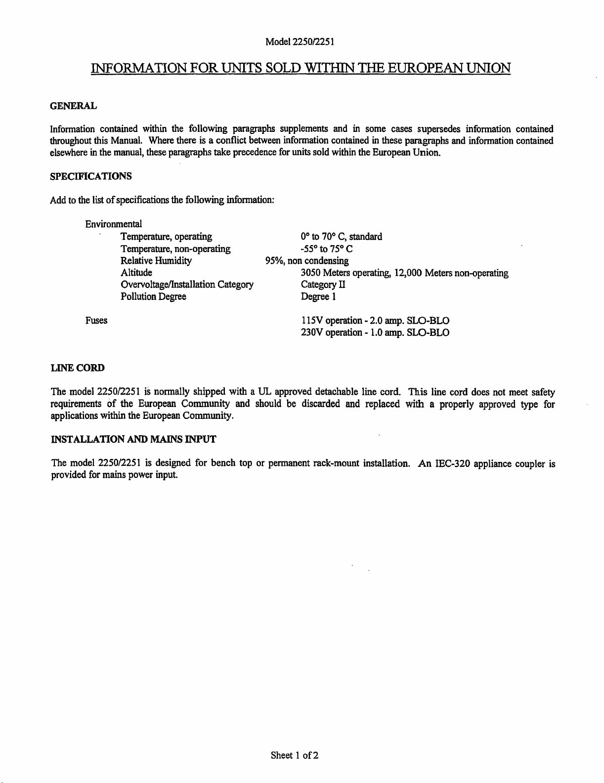
GENERAL
Information
contained
within
the
following
paragraphs
supplements
and
in
some
cases supersedes
information
contained
throughout
this
Manual.
Where
there is a conflict
between
information
contained
in
these paragraphs
and
information
contained
elsewhere
in
the
manual,
these
paragraphs take
precedence
for
units
sold
within
the
European Union.
SPECIFICATIONS
Add
to
the
list
of
specifications
the
following
information:
Environmental
Fuses
LINE
CORD
Temperature,
operating
Temperature,
non-operating
Relative
Humidity
Altitude
Overvoltage/Installation
Category
Pollution
Degree
0°
to
70° C, standard
-55°
to
75°
C
95%,
non
condensing
3050
Meters
operating,
12,000 Meters
non-operating
Category
TI
Degree 1
115V
operation -
2.0
amp.
SLO-BLO
230V
operation -
1.0
amp.
SLO-BLO
The
model
2250/2251
is
normally shipped with a UL approved detachable line cord. This line cord
does
not
meet
safety
requirements
of
the
European
Community
and
should
be discarded
and
replaced
with
a properly
approved
type
for
applications within the
European
Community.
INSTALLATION
AND
MAINS
INPUT
The
model
2250/2251
is
designed for bench top or permanent rack-mount installation.
An
IEC-320 appliance coupler
is
provided
for
mains
power
input.
Sheet 1
of2
Model
2250/2251
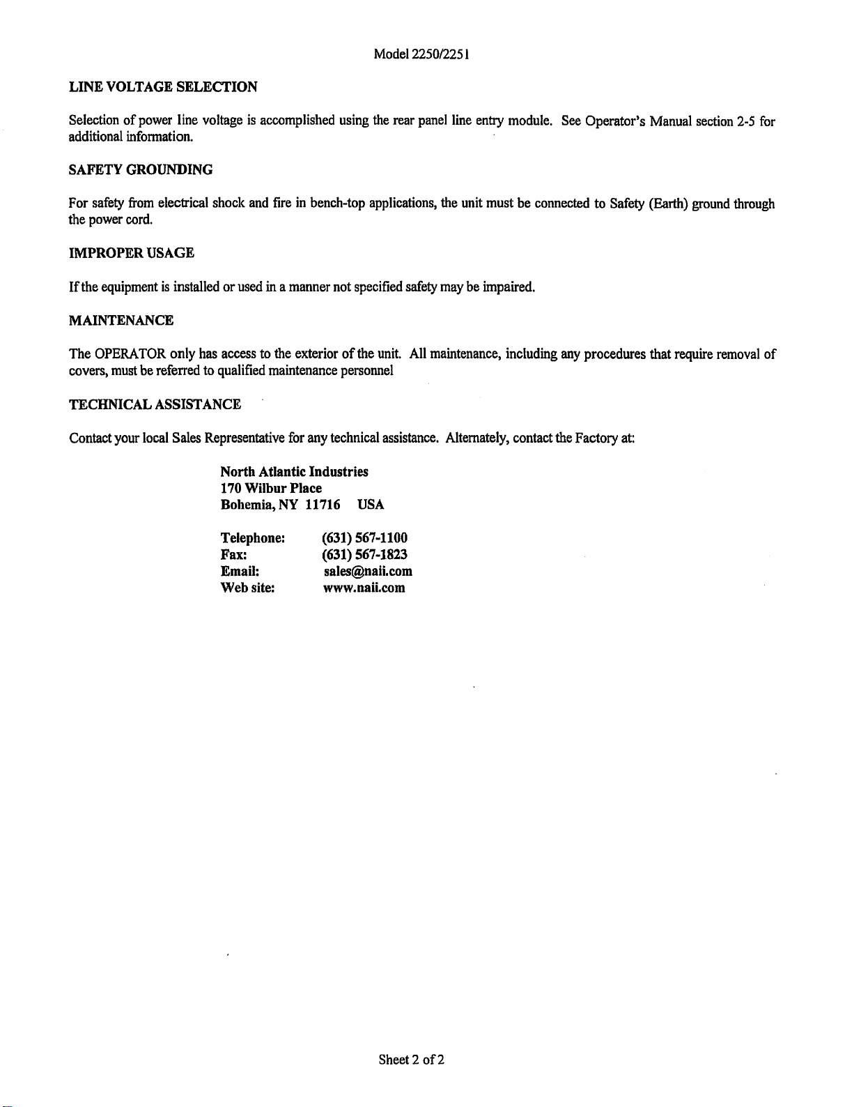
LINE
VOLTAGE
SELECTION
Selection
of
power
line
voltage
is
accomplished
using
the
rear
panel
line
entry
module.
See
Operator's
Manual
section
2-5
for
additional
information.
SAFETY
GROUNDING
For
safety
from
electrical
shock
and
fire
in
bench-top
applications,
the
unit
must
be
connected
to
Safety
(Earth)
ground
through
the
power
cord.
IMPROPER
USAGE
If
the
equipment
is
installed or
used
in a
manner
not
specified
safety
may
be
impaired.
MAINTENANCE
The
OPERA
TOR
only
has
access
to
the
exterior
of
the
unit.
All
maintenance,
including
any
procedures that
require
removal
of
covers,
must
be
referred
to
qualified
maintenance
personnel
TECHNICAL
ASSISTANCE
Contact
your
local
Sales
Representative
for
any
technical
assistance.
Alternately,
contact
the
Factory
at:
North
Atlantic Industries
170
Wilbur
Place
Bohemia,
NY
11716
USA
Telephone:
Fax:
Email:
Web
site:
(631)
567-1100
(631)
567-1823
www.naii.com
Sheet
2
of2
MODEL
2250 (OM-I-5026B) ERRATA SHEET
ER-1-5026B-E
10
JULY 14, 1998
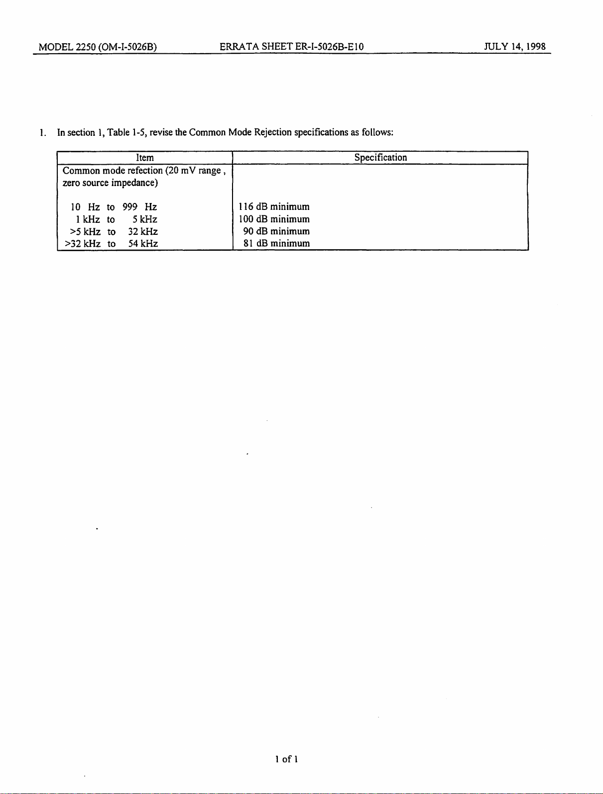
1.
In
section
1,
Table
1-5,
revise
the
Common
Mode
Rejection specifications
as
follows:
Item
Specification
Common mode refection
(20
mV range ,
zero source impedance)
10
Hz
to 999 Hz
116
dB
minimum
I kHz
to
5 kHz 100 dB minimum
>5
kHz to
32kHz
90 dB minimum
>32 kHz to
54kHz
81
dB minimum
1
of
1
MODEL
2250
(OM-1-5026B)
ERRATA
SHEET
ER-I-5026B-E9
I.
In
section
2,
paragraph
2-4
(INSTALLATION),
add
the
following
infonnation after
the
CAUTION
message:
NOTE
If
the
DAV
has
not
been
used
for
an
extended
period
of
time,
the
nickel-
cadmium
memory
backup
battery
may
become
discharged. Power
up
the
DAV
and
allow
it
to
run
for
a
minimum
of
8
hours,
then press the front
panel
CLEAR
VAR
key.
JUNE
5,
1998
2.
In
section
2,
paragraph
2-9
(OPERATIONAL
CHECKOUT
PROCEDURE),
add the following
note
after
the
paragraph
heading:
NOTE
Before
beginning
the checkout procedure,
press
the
front panel
CLEAR
VAR
key.
1
of
1

MODEL 2250
(OM-1-5026B)
PRODUCT REVISION
SHEET#
9-96 SEPTEf\.fBER 12, 1996
1.0
ASSE~LIES
AND REVISIONLEVELS AFFECTED:
Top
Assembly
NAI PIN 402250 Revision
K.
These changes
may
also
be
applicable to assemblies retrofitted with
new
finnware.
2.0
CHANGES:
In section 1change the following:
a.
In
table 1-1
add
the following:
NAI
Manual Number
lvfM-1-5027
A
MM-I-5026B
ITOTAL/AVG
Conforuration)
b. In table 1-2 add the following:
NAI
Manual Number
:MM:-I-5027
A
:MM:-1-5026B
ITOT
AL/
A
VG
Confirruration)
Model
Version
5.15
6.11
Model
Version
1.17
2.13
Check Sum Number
n5.15
n6.11
Check Sum Number
cl.17
c2.13

MODEL
2250 (OM-I-5026B)
ERRATA
SHEET
ER-I-5026B-E7
JUNE
13.
1991
In
Section
2
paragraph
2-7
add
the
following
after
the
last
sentence:
(Optional
rear
input
adapter
cable.
NAI
PIN
548792,·
is
available
£or
use
with
the
Model 225
Emulation
feature/option
F3.)
1
of
1
Publication No. OM-I-50268
OM-I-5026B
STATUS
OF
PUBLICATION
This manual applies
to
units with single Feature/Option numbers
(FX)
only.
Original -April
1989
Change
1 - October 1989
Change
2 - January 1990
Change
3 -
July
1990
Change
4-
May 3, 1991
Change
5 - February 20, 1992
Change
6 - June 12,
1996
SOFTWARE CONTAINED IN PROM(S)
HAS
BEEN
COPYRIGHTED
BY
NORTH ATLANTIC INDUSTRIES, INC.
1991
A

Sec./Para.
SECTION
1
1-1
1-1.1
1-1.2
1-1.3
1-1.4
1-1.5
1-1.6
1-1.
7
1-2
1-3
1-4
1-5
SECTION
2
2-1
2-2
2-3
2-4
2-5
2-5.1
2-5.2
2-6
2-7
2-7.1
2-7.2
2-8
2-8.1
2-8.2
2-8.3
2-8.4
2-8.4.1
2-8.4.2
2-8.5
2-8.5.1
2-8.5.
1.
1
2-8.5
.1.2
2-8.6
2-9
2-9.1
2-9.2
2-9.2.1
2-9.2.2
2-9.2.3
2-9.3
2-9.4
Change 3
OM-I-5026B
TABLE
OF
CONTENTS
GENERAL
INFORMATION.
1-1
Introduction
• • • • • • • • • 1-1
Section
1 -
General
Information.
• • • • • • 1-1
Section
2 -
Installation
and
Preparation
for
Use • • • 1-1
Section
3 -
Operation
• • • • • • • • • • • • • • 1-1
Section
4
-IEEE-488
Standard
Digital
Interface
Programming • • • • • • • • • • • • • • • 1-1
Section
5 -IEEE
MATE
Control
Interface
Intermediate
Language
Option.
Section
6 -
Theory
of
Operation.
Section
7 -
Update
Information
•••
Features
and
Options
••••••
Functional
Description
Physical
Description
Specifications
••••
INSTALLATION
AND
PREPARATION
FOR
USE
Introduction
••
Unpacking
••••••••
Inspection
•••••
Installation
••••
Power
Requirements
••••
Line
Voltage
Selection
Circuit
Card
••
Grounding.
• • • • • • •
••
Mounting
Procedures
••••••••••••
Initial
DAV
Setup
•••••••••••
Initial
Factory
Switch
Settings
•••
Emulation
of
NAI
Model 225
Selecting
Custom
DAV
Setups
••••••••
Top Cover Removal • • • •
·•
• • • •
Selection
of
Remote Programming (IEEE-488)
Interface
Language
•••••
Model 225
Device
Clear
(DCL)
Options.
Channel
Selection
for
Phase
Lock
Model 2250
Operation
•••••••••
Model 225
Emulation
·•
• • • • • • • •
Selection
of
SUM
or
AVG
TOTAL
Mode
•••••••••
Types
of
TOTAL
modes
••••••
TOTAL
(SUM)
Mode
••••••
TOTAL
(AVG)
Mode
••••••••
Recorder
Output
Voltage
Selection
(I/0
Circuit
Card Assembly)
.•••••.•
Operational
Checkout
Procedure
••
Test
Equipment
Required
•••••
Continuity
and
Isolation
Checks
••••••
Continuity.Tests.
•
•••
Isolation
Checks
••••
Hipot
Tests
••••••
Function
Verification
•••
Amplitude
Accuracy
and
Phase
Check, 400
Hz
••
i
1-1
1-1
1-1
1-3
1-3
1-3
1-6
2-1
2-1
2-1
2-1
2-1
2-1
2-3
2-4
2-4
2-4
2-4
2-10
2-10
2-10
2-10
2-11
2-11
2-11
2-12
2-12
2-12
2-12
2-12
2-13
2-14
2-14
2-14
2-14
2-15
2-15
2-15
2-21
Sec./Para.
2-9.5
2-9.6
SECTION
3
3-1
3-1.1
3-1.2
3..;1.3
3-2
3-3
3-4
3-4.1
3-4.
1.
1
3-4.1.2
3-4.1.3
3-4.2
3-4.2.1
3-4.2.2
3-4.3
3-4.3.1
3-4.3.2
3-4.4
3-4.4.1
3-4.4.2
3-4.5
3-4.5.1
3-4.5.2
3-4.6
3-4.6.1
3-4.6.2
3-4.7
3-4.7.1
3-4.7.2
3-4.7.3
3-5
3-5.1
3-5.2
3-6
3-0.1
3-6.2
3-6.3
3-7
3-7.1
3-7.2
3-7.3
3-7.4
3-8
3-8.1
3-8.2
3-8.3
3-8.4
OM-I-5026B
TABLE
OF
CONTENTS
(Continued)
Amplitude Accuracy and
Phase
Check, Wideband
IEEE-488
Interface
Test
••••••••••
. .. .. . .
... ..
OPERATION.
. . ... . . . . . . . . . . . . . . .. . ..
Introduction
•••••••••••••••••••••
Model 225
Compatible
Operation.
• • • • • • • • • • • •
Custom
DAV
Setups
•••••••••••••••••••••
Remote Programmed
Operation
•••••••••••••
Front
Panel
Controls
and
Indicators
••••••••••••
Rear
Panel
Controls
and
Indicators
•••••••••••••
Modes
of
Operation
•••••••••••••••••
TOTA!.,
Mode. • • • • • • • • • • • • • • • • • • • •
TOTAL
Mode
Measuring
Techniques
••••••••••••••
Measurement
Modifiers.
• • • • • • • •
Display
Ma
th
Modi£
iers.
• • • • • • • • • • •
FUNDamental Mode. • • • • • • • • • • • • • • • • •
Measurement
Modifiers
• • • • • • • • • • • • • •
Display
Math
Modifiers.
• • • • • • •
IN
PHASE
Mode
• • • • • • • • • • • • • • • •
Measurement
Modifiers
••••••
. . . ......
Display
Ma
th
Modifiers.
• • • • • • • • •
QUADrature
Mode
• • • • • • • • • •
Measurement
Modifiers
• • • • • • • ...... . ..
Display
Math
Modifiers.
• •
••
. . .. ..
PHASE
ANGLE
Mode.
• • • • • • • • • • • •
Measurement
Modifiers
• • • • • •
Display
Math
Modifiers
••••••••
THD
Mode.
• • • • • • • • • • • .... . ...
Measurement
Modifiers
••••••
Display
Math
Modifiers
••
. . .. . . ... . .. .
. .... . .. . ..
RATIO
R Modes
•••••
. .. . . .. . .. . . .
RATIO
R Submodes. • • • • • • • •
Measurement
Modifiers
. .. ..
. . . . . . . . .
Display
Math
Modifiers.
.. . . . .
Ranges
of
Operation
•••
.. . . . ... . . .
. .. . . . .. . .
. .... . . . . . . ..
Voltage
Ranges.
.•
• • • • • • •
Ratio
Ranges. • • • • •
Measurement Channels
••••••
...... . . ..
REFerence
Channel.
• • •
••••••
SIGnal
Channel.
• • • • • • • •
•••
Phase Lock
Synchronization
Reference
••••
Measurement
Modifiers.
•
•••
Harmonic Measurement. • • • • • • • • • • •
Frequency
Preset.
• •
•••••••••
Display
Averaging
•••••••••••••
Track/Hold.
• • • • • • • • • • • •
Display
Math
Modifiers.
•
••••••
Phase
Offset.
• •
•••••••••
Variable
Scale.
•
•••
Offset.
• • • • • • • • •
•••••
+180°
Phase
• •
•••••
ii
. . .
. .. . . . ..
... . ..
. . . . . ...
. . . . . . . .
.. . . . . . .
. . . . .
. . . .. .
2-23
2-23
3-1
3-1
3-1
3-1
3-1
3-1
3-10
3-12
3-12
3-12
3-12
3-12
3-13
3-13
3-13
3-13
3-14
3-14
3-14
3-14
3-15
3-15
3-15
3-15
3-16
3-16
3-16
3-16
3-16
3-17
3-18
3-18
3-18
3-18
3-18
3-19
3-19
3-19
3-19
3-19
3-20
3-20
3-20
3-20
3-20
3-21
3-21
3-21

Sec./Para.
3-8.5
3-8.6
3-9
3-9.1
3-9.2
3-9.3
3-10
3-10.1
3-10.2
3-10.3
3-11
3-11.1
3-11.2
3-12
3-12.1
3-12.2
3-12.3
3-12.4
3-12.4.1
3-12.4.2
3-12.5
3-12.6
3-12.7
3-12.7.1
3-12.7.2
3-12.7.3
3-12.7.4
3-12.
8
3-12.9
3-12.10
3-12.11
3-12.12
3-12.13
3-12.14
SECTION
4
4-1
4-1.1
4-1.2
4-1.3
4-1.4
4-1.5
4-1.6
4-2
4-2.1
4-2.2
4-2.3
4-3
4-3.1
4-3.
1.
1
4-3.1.
2
OM-I-5026B
TABLE
OF
CONTENTS
(Continued)
Percent
Deviation
••
. .
dB. • • • • • • •
Keypad
Operation
•••••••••••••••••••••
Enter
Data.
• • • • • • • • •
•••••••
Read/Modify
Data.
• • • • • •
••••••••••
Clear
Data
•••••••••••••••••••••••••
Self-Calibration
• • • • • • • • • • • • •
••
Ten
Frequency
Self-Calibration
Storage.
• • • • •
•••
TOTAL
(AVG)
Calibration
• • • • • • • • • • • • •
AUTOCAL
Operation
• • • • • • • • • • • • • •
Recorder
Output
• • • • • • • • • • • • • • • • • • • •
Output
Options.
• • • • • • •
••••••••••
Recorder
Outputs
in
Various
Operating
Modes • • • • • •
Typical
Applications
• • • • • • • • • • • •
AC
Voltage
Measurement. • • • • • • • • • • • • • • • • • •
Phase
Sensitive
AC
Voltage
Measurement
•••••••••••
Phase
Angle Measurement
••••••••••••••••••
Frequency
Response
Measurements
in
dB
•••••••••••
Setup
Frequencies.
• • • • • • • • • • •
•••••••
Measure
Response
•••••••••
THD
Measurements. • • • • • • • •
Percent
Deviation
Measurements
••
. . . . . . ..
Harmonics Measurements
••••••
Harmonic
Fundamental
Amplitude
••••
. .. .
Harmonic
lnphase
Component
Amplitude
••••••••••••
Harmonic
Quadrature
Component
Amplitude
••••••••••
Harmonic
Phase
Angle Measurement
••••••••••
Transfomation
Ratio
Measurement
••••
Synchro/Resolver
Bridge
Null
Indicator
•••
Synchro
Electrical
Zero
(Null)
Tests
••••••
Impedance Angle and Power
Factor
Measurements
••
. . .
. ..
Impedanee
Magnitude
• • • • • • • • • • • • • • • • • • • •
AC
Resistance
and
Reactance
Measurements
•••
Condition
Transducer
Output
for
Convenient
Display.
IEEE-488
STANDARD
DIGITAL
INTERFACE
PROGRAMMING.
. . . . .
Introduction
. . . . . . . . . . . .
Interface
Functions
Supported
••••
Remote Program Language
Selection
••
DAV
Address • • • • • • • • • • • • • • • •
IEEE-488
Interface
Connections
•••••••
Power-Up
•••••••••••
DAV
Front
Panel
Annunciators
••
.. . . .
. . ..
. .. . . . ..
Bus
C0Dm1ands
• • • • • • • • • • • • • • • • • • • •
Bus
Command
Descriptions.
• • • • • • • • • • • • • •
Default
Settings.
• • • • • • • • • • • • • •
••
Serial
Poll
• • • • • • • • • • • • • • • • • • • • • • • •
Model 22~0
NATIVE
Language
Device
Dependent Messages
•••
Mode
Pro~::.
amming. • • • • • • • • • • . . ..
Mode
Programming
Examples.
• • • •
••
Ratio
R
Mode
Programming Examples
•••••
. . ..
iii
3-21
3-21
3-22
3-22
3-22
3-22
3-23
3-23
3-23
3-23
3-23
3-24
3-24
3-24
3-25
3-26
3-27
3-28
3-28
3-28
3-29
3-29
3-30
3-30
3-30
3-31
3-31
3-32
3-33
3-34
3-35
3-36
3-37
3-38
4-1
4-1
4-1
4-1
4-2
4-2
4-2
4-5
4-5
4-5
4-6
4-6
4-6
4-6
4-6
4-7
Sec.
/Para.
4-3.2
4-3.2.1
4-3.2.2
4-3.3
4-3.4
4-3.4.1
4-3.4.2
4-3.4.3
4-3.4.4
4-3.5
4-3.5.1
4-3.5.2
4-3.5.3
4-3.5.4
4-3.5.5
4-3.5.6
4-3.6
4-3.
7
4-4
4~4.1
4-4.2
4-4.3
4-4.4
4-5
4-6
4-6.1
4-6.2
4-6.3
4-6.4
4-7
4-8
4-8.1
4-8.
1.1
4-8.
1.2
4-8.2
4-8.2.1
4-8.2.2
4-8.2.3
4-8.2.4
4-8.2.5
4-8.2.6
4~8.2.7
4-8.3
4-8.4
4-9
4-9.1
4-9.
1.1
4-9.
1.2
4-10
4-11
4-11.1
OM-I-5026B
TABLE
OF
CONTENTS
(Continued)
Range Programming • • • . • • • • • • • • • • • • •
Voltage
Range
Programming.
•
•••••
Ratio
Range
Programming.
•
•••
Measurement Channel Programming
••••
Measurement
Modifier
Programming
••••••••••••••
Harmonic Measurement Programming
••
Frequency
Preset
••••••••••••
Data
Averaging.
• • • • • • • • •
•••
Track/Hold
Programming
•••••••••
Data
Math
Modifier
Programming
••
Phase
Offset
Programming
••
Variable
Scale
Programming
••
Offset
Programming
••••.•••••••••
+180°
Phase
Programming
•••
Percent
Deviation
Programming
•••
dB
Programming• • • • • • • • • • • • •
Self-Calibration
Programming. •
•••••••
AUTO
CAL
Function
Programming
Model 2250
NATIVE
Language
Talk
Messages
••
TALK
Message Format Programming
•••••••
Main
Display
Transmission
Format
•••••••
Frequency
Display
Transmission
Format.
Status
Transmission
Format
••••••••••
Model 2250
NATIVE
Language
Serial
Poll
Model 2250
NATIVE
Language
Service
Request
Programming
Assert
SRQ
With
Stable
Data
or
Measurement Timeout
•••••
Assert
SRQ
Continuously
Programming
•••••
Assert
SRQ
On
External
Trigger
Programming
••
Cancel
SRQ
Function
Programming
•••••••••
Model 2250
NATIVE
Language Group
Execute
Trigger
Programming
••••••••••••••••••
Model 225
Emulation
Listen
Message Programming
Listen
Message
Data
Format.
• • • • •
Long Format
Listen
Syntax
••••••••••••
Short
Format
Listen
Syntax.
• • • • • • • • • • • •
••
Model 225
Emulation
Listen
Instructions
and
Arguments.
Listen
Instructions
Mode
Arguments.
• • • • •
Range
Arguments.
• •
••
Frequency
Arguments
•••••••••
Reference
(Phase)
Offset
Arguments.
Variable
Scale
Arguments
••••
Data
Output
Format
Programming.
Modifier
Value
Storage
••••••
Self-Calibration
Programming
•••
Model 225
Emulation
Talk
Messages •
Talk
Message
Data
Format.
•
••
Long
Talk
Message Format
••••••••
. ... . .
Short
Talk
Message
Format.
• • •
•••
Model 225
Emulation
Serial
Poll.
Model 225
Emulation
Service
Request
•
..
. . . . .
. . .
. . .
Assert
SRQ
With
Stable
Data
or
Measurement
Timeout.
. . . .
iv
4-8
4-8
4-8
4-8
4-9
4-9
4-9
4-10
4-10
4-10
4-10
4-10
4-11
4-11
4-12
4-12
4-12
4-13
4-13
4-13
4-14
4-14
4-14
4-15
4-15
4-16
4-16
4-16
4-17
4-17
4-20
4-20
4-20
4-20
4-21
4-21
4-21
4-21
4-22
4-22
4-22
4-23
4-23
4-23
4-24
4-24
4-24
4-24
4-25
4-25
4-25
Sec.
/Para.
4-11..2
ij-fl.3
~
12.
JI--•
3
SECTION
5
5-1
5-1.1
5-1.2
5-1.3
5-2
5-2.1
5-2.2
5-2.3
5-2.4
5-2.5
5-2.6
5-2.6.1
5-2.6.2
5-2.6.3
5-3
5-3.1
5-3.2
5-3.3
5-3.4
5-3.5
5-3.6
5-3.7
5-3.8
5-3.9
5-3.10
5-3
.11
5-3
.12
5-3
.13
5-3.14
5-4
5-5
5-6
5-7
5-8
5-9
5-10
5-11
5-12
5-12.1
5-12.2
5-12.3
5-12.4
5-13
Change 3
f
OM-I-5026B
TABLE
OF
CONTENTS
(Continued)
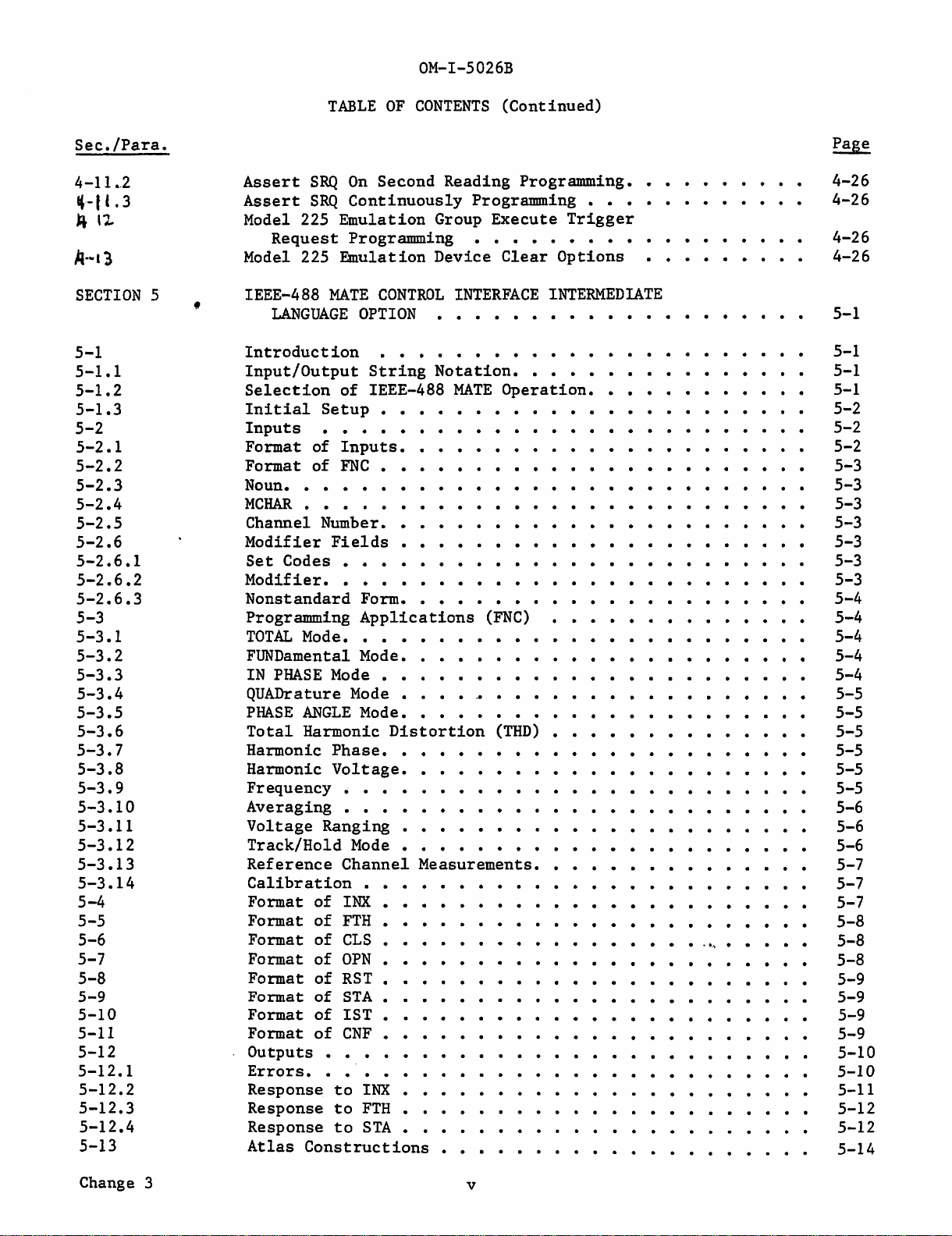
Assert
SRQ
On
Second Reading Programming.
Assert
SRQ
Continuously
Programming.
Model 225
Emulation
Group
Execute
Trigger
Request
Programming
Model 225
Emulation
Device
Clear
Options
IEEE-488
MATE
CONTROL
INTERFACE
INTERMEDIATE
LANGUAGE
OPTION
Introduction
Input/Output
String
Notation.
•
Selection
of
IEEE-488
MATE
Operation.
Initial
Setup.
Inputs
Format
of
Inputs.
Format
of
FNC
•
Noun.
MCHAR.
Channel Number.
Modifier
Fields
Set
Codes •
Modifier.
Nonstandard
Form.
Programming
Applications
(FNC)
TOTAL
Mode.
FUNDamental Mode.
IN
PHASE
Mode.
QUADrature
Mode.
PHASE
ANGLE
Mode.
Total
Harmonic
Distortion
(THD)
Harmonic
Phase.
Harmonic
Voltage.
Frequency.
Averaging.
Voltage
Ranging.
Track/Hold
Mode.
Reference
Channel
Measurements.
Calibration.
Format
of
INX.
Format
of
FTH.
Format
of
CLS.
Format
of
OPN.
Format
of
RST •
Format
of
STA.
Format
of
IST.
Format
of
CNF.
Outputs
•
Errors.
Response
to
INX.
Response
to
FTH.
Response
to
STA.
Atlas
Constructions.
V
. .
.
..
..
, .
4-26
4-26
4-26
4-26
5-1
5-1
5-1
5-1
5-2
5-2
5-2
5-3
5-3
5-3
5-3
5-3
5-3
5-3
5-4
5-4
5-4
5-4
5-4
5-5
5-5
5-5
5-5
5-5
5-5
5-6
5-6
5-6
5-7
5-7
5-7
5-8
5-8
5-8
5-9
5-9
5-9
5-9
5-10
5-10
5-11
5-12
5-12
5-14

Sec./Para.
5-13.1
5-13.2
5-13.3
5-13
.4
5-13.5
5-13.6
5-13.7
5-13.8
5-13.9
5-13.10
5-14
5-14.1
5-14.2
5-14.3
5-14.4
5-14.5
5-14.6
5-14.7
5-14.8
5-14.9
5-14.10
5-14.11
SECTION
6
6-1
6-2
6-2.1
6-2
.1.1
6-2.1.2
6-2.2
6-2.3
6-2.4
6-2.5
6-2.6
6-2.7
6-2.8
6-2.9
6-2
.10
6-2.11
6-2
.12
6-3
6-3.1
6-3.2
SECTION
7
7-1
OM-I-5026B
TABLE
OF
CONTENTS
(Continued)
Calibration
••••••••••••••••••••••••
Standard
(Non-Referenced)
AC
Voltage
Measurement
(True
Rms
Voltage)
•••••••••••••••••••
Referenced
AC
Voltage
Measurements (True
Rms
Voltage)
•••
Referenced
AC
Voltage
Measurements -FUNDamental
Component. • • • • • • • • • •
·•
• • • • • • • • •
Referenced
AC
Voltage
Measurements -
IN
PHASE
Component
••
Referenced
AC
Voltage
Measurements -QUADrature
~
Component. • • • • • • • • • • • • • • • • • • • • • • •
Referenced
AC
Voltage
Measurements -Harmonic Component
••
PHASE
ANGLE
Measurements -FUNDamental Component
••••••
PHASE
ANGLE
Measurement -Harmonic Component.
Total
Harmonic
Distortion
Measurement
••••••••
CIIL
Railroad
Diagrams
••••••••••••••••••
Standard
(Non-Referenced)
AC
Voltage
Measurement
True
RMS
• • • • • • • • • • • • • • • • • • • •
Standard
(Referenced)
AC
Voltage
Measurement
True
RMS
•••
Referenced
AC
Voltage
Measurement FUNDamental Component
••
Referenced
AC
Voltage
Measurement
IN
PHASE
Component
••••
Calibration
•••••••••••••••••••••
~
Referenced
AC
Voltage
Measurement QUADrature Component
•••
Referenced
AC
Voltage
Measurement Harmonic Component
••••
PHASE
ANGLE
Measurement FUNDamental Component •
PHASE
ANGLE
Measurement Harmonic Component
•••••••••
Total
Harmonic
Distortion.
• • • • • • •
••
Summary
of
MATE
Programming
Syntax.
• • • •
••
THEORY
OF
OPERATION.
Introduction
• • • •
••••••••••
Overall
Block
Diagram
Discussion
••••
Front-End
Section.
• • • • • • • • •
••••••
Input
Signal
Path
••••••••••••••••
Reference
Signal
Path.
• • • •
•••••••••••
Analog
to
Digital
Converters.
• • • • • • • • • • •
Filter
CCA.
• • • • • • • • • • •
.•
• • • • •
The
Accumulator
(2)
• • •
•••••••
Timing and
Control
CCA.
• • • •
••
. ....
Phase-Locked Loop (PLL)
CCA
••••••••
. . . .
Autocalibration
CCA
••••••••••••••••••
Microprocessor
CCA
•••
,.:ROM
and
RAM
(Memory
CCA)
•
.
Input/Output
CCA.
• • • •
The
Display
Driver
CCA
••••
Keyboard and
Display
CCA.
Power
Supplies
•••••
System
Level
Power Supply •
Isolated
Power
Supplies
•
UPDATE
INFORMATION
. . . . .
. .. . . . .. . . . .
. . . . . . . . . . ...
. . . . . .
. . .. .
. . . . . .
Introduction
. . . . . . . . . . . . . . . . . . . . . . .
5-14
5~14
5-15
5~15
5-16
5-16
5-17
5-18
5-18
5-19
5-20
5-20
5-21
5-22
5-23
5-24
5-25
5-26
5-27
5-28
5-29
5-30
6-1
6-1
6-1
6-1
6-1
6-1
6-3
6-3
6-3
6-3
6-3
6-3
6-3
6-3
6-4
6-4
6-4
6-4
6-4
6-4
7-1
7-1
vi
Change 3

Figure
1-1
2-1
2-2
2-3
2-4
2-5
2-6
3-1
3-2
4-1
4-2
4-3
4-4
4-5
5-1
6-1
Table
1-1
1-2
1-3
1-4
1-5
2-1
2-2
2-3
2-4
2-5
2-6
2-7
2-8
3-1
3-2
3-3
3-4
3-5
4-1
4-2
4-3
4-4
4-5
Change 2
OM-I-5026B
LIST
OF
ILLUSTRATIONS
Model 2250
Digital
Analyzing
Voltmeter
DAV
Outline
and
Dimension
Drawing.
Inserting
Voltage
Selection
Circuit
Top
Cover
Removal
•••.••.••
Optional
Function
Switch
Locations
Function
Verification
••••.••
Amplitude
Accuracy
and
Phase
Check,
Front
Panel
Controls
and
Indicators
Rear
Panel
Controls
and
Connectors
Rear
Panel
DIP
Switches
Card
(400
Hz)
Long
Format
Listener
Format.
•
•••••
Short
Format
Listener
Format
.••••
Long
Format
Talk
Message
•••.•••••
Short
Format
Talk
Message
••
IEEE-488
MATE
Address
Switch
Selection
Model 2250
DAV
Overall
Block
Diagram
LIST
OF
TABLES
Fl/FlX
Model
Identification
Chart.
F2/F2X Model
Identification
Chart
•
Features
and
Options
Model 2250
Major
Assemblies.
Specifications
.•••.•.
Initial
Factory
Switch
Settings
for
Fl
Option.
Initial
Factory
Switch
Settings
for
F2
Option
...••
Initial
Factory
Switch
Settings
for
F3
Option
.••••
Test
Equipment
• • . . • . • •
Function
Verification
Procedure
•••..
Amplitude
Accuracy
and
Phase
Check
•••.••••.•
Amplitude
Accuracy
and
Phase
Check (Wideband) •
IEEE-488
Test
Program
••••.•••
Front
Panel
Controls
and
Indicators.
Rear
Panel
Controls
and
Connectors
Rear
Panel
Mating
Connector
Contacts
Channel
Used
For
Phase
Lock
••
De
Recorder
Outputs
vs.
Mode
•••.•
IEEE-488
Interface
Functions
and
Descriptions
IEEE-488
Interface
Language
Selection
••••
Device
Address
Codes
••••...•..••
IEEE-488
Interface
Connector
Pin
Assignments
Bus
Connnands
• • • • • • . • • • • . . • • •
vii
1-5
2-2
2-3
2-10
2-11
2-20
2-22
3-1
3-10
4-2
4-20
4-20
4-24
4-24
5-2
6-2
1-2
1-2
1-3
1-4
1-6
2-4
2-6
2-8
2-14
2-16
2-21
2-23
2-24
3-2
3-10
3-11
3-19
3-24
4-1
4-1
4-3
4-4
4-5

!ml§.
4-6
4-7
4-8
4-9
4-9A
4-10
4-11
4-12
4-13
4-14
4-15
4-16
4-17
4-18
4-19
4-20
4-21
4-22
4-23
4-24
5-1
5-2
5-3
5-4
OM-1-5026B
LIST
OF
TABLES (Continued)
Mode Programming Mnemonics
..........................................
.
Modifiers
Allowed
In
Each
Mode
..................•.....•....••..........•
Voltage Range Codes • • . . . . . . . . . . . . . . . . . • • . . . . • . . • . . . . . • . • . . . . . . • . . . . . .
Ratio Range Codes . . . . . . . . • . . . . . . . . . . . . . . . . . . • • . . . . . . . • . . . . . . . . . • . . . .
Serial Poll Status Byte . . . . . . . . . . . . . . . . . . . . . . . • • • . • . . . . . • . • • • • . . . . . . . . .
2250 Native Language Reference Guide • . . . . . . • • • • • . . • . • . • . • • . . . . • . . . . . . .
..
Calibration Error Descriptions . . . . . . . . . . . . . • • . . . . . . . . . . . . . . . • . . . . • . . . . . . .
Model
225
Emulation Listen Instructions
....••......•.....•......•..•......
Mode Programming
.•.............................•.....••..•..•..•..
Range Arguments
..............................•....••...•.........•
Frequency Arguments . . . . . . . . . . . . . . . . . . . . . . . . . . . • . . . . . . • • . . . . . . . . . . . .
Reference Offset Arguments . . . . . . • . . . . . . . . . • . . . . . • • • . • . . . . . . . . . • • . • . . . .
Variable Scale Arguments
...•.........................•........•.......
Data
Output
Format Arguments
.............................•....•.•.....
Model
225
Emulation Serial Poll Status Byte
..........•.•.....•..............
Service Request Arguments . . . . . . . . . . . . . . . • . . • • . . . . . . . .
..
• . . . . . . . . • . . . . .
Group Trigger Enable Arguments . . . . . . . . . . . • • . • • • • . . . . . . • . . . • . . • . . . . . . . . .
225
Emulation Device Clear Options . . . . . . . • . • . • . . . . . . . . . . . . • • . . . . . . . . . .
..
Model
225
Emulation Programming Guide
•••........•...................•....
Model
225
Emulation Long Talk Message Summary
..........•....•.......•....
Voltage Range Selection . . . . . . . . . . . . . . . . . . . • . . . . . . . . . . . • . . . . . . . . . . • . . . . .
Error Messages
........................•...•......•..•..............
CIIL Codes
..........................•.............................
Modifier Limits . . . . . . . . • . . . . . . . • . . • . . . . . . . . • . . . . . . . • . . . . . . . . . . . . . . . . .
f.w.
4-6
4-7
4-8
4-8
4-15
4-17
4-19
4-21
4-21
4-22
4-22
4-22
4-23
4-23
4-25
4-26
4-26
4-27
4-28
4-29
5-6
5-10
5-12
5-13
viii Change 6

WARNING
VARNING
Failure
to
ground
the
chassis
could
bring
operator
and
maintenance
personnel
in
contact
with
high
voltages
capable
of
causing
personal
injury
or
death.
WARNING
If
the
top
cover
of
the
Model 2250
is
removed
while
the
guard
terminals
are
driven
with
a
voltage,
operator
and
maintenance
personnel
could
come
in
contact
with
high
voltages
capable
of
causing
personal
injury
or
death.
WARNING
The
front
SIG
and
REF
binding
posts
are
connected
to
the
corresponding
rear
panel
connectors.
If
a
high
voltage
is
applied
to
the
front
input
binding
posts,
high
voltages
capable
of
causing
personal
injury
or
death
will
appear
at
the
rear
input
connectors.
Similarly,
if
a
high
voltage
is
applied
at
the
rear
input
connectors,
a
high
voltage
capable
of
causing
personal
injury
or
death
will
appear
at
the
front
binding
posts.
1-1
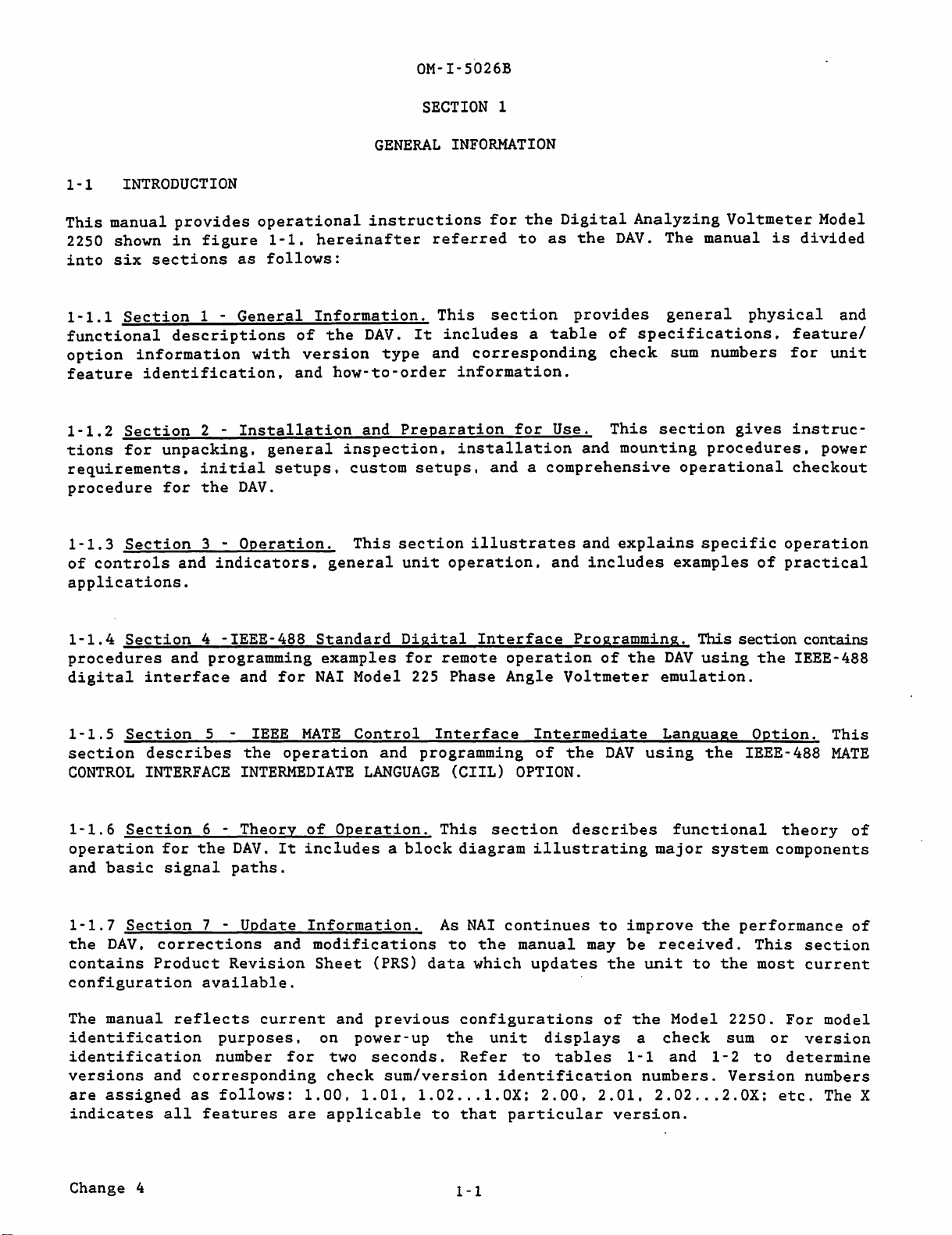
INTRODUCTION
OM-I-5026B
SECTION
1
GENERAL
INFORMATION
This
manual
provides
operational
instructions
for
the
Digital
Analyzing
Voltmeter
Model
2250 shown
in
figure
1-1.
hereinafter
referred
to
as
the
DAV.
The
manual
is
divided
into
six
sections
as
follows:
1-1.1
Section
1 -
General
Information.
This
section
provides
general
physical
and
functional
descriptions
of
the
DAV.
It
includes
a
table
of
specifications.
feature/
option
information
with
version
type
and
corresponding
check
sum
numbers
for
unit
feature
identification.
and
how-to-order
information.
1-1.2
Section
2 -
Installation
and
Preparation
for
Use.
This
section
gives
instruc-
tions
for
unpacking,
general
inspection.
installation
and
mounting
procedures.
power
requirements.
initial
setups.
custom
setups,
and
a
comprehensive
operational
checkout
procedure
for
the
DAV.
1-1.
3
Section
3 -
Operation.
This
section
illustrates
and
explains
specific
operation
of
controls
and
indicators.
general
unit
operation.
and
includes
examples
of
practical
applications.
1-1.
4
Section
4 - IEEE- 488
Standard
Digital
Interface
Programming.
This
section
contains
procedures
and
programming
examples
for
remote
operation
of
the
DAV
using
the
IEEE-488
digital
interface
and
for
NAI
Model 225
Phase
Angle
Voltmeter
emulation.
1-1.
5
Section
5 - IEEE
MATE
Control
Interface
Intermediate
Language
Option.
This
section
describes
the
operation
and
programming
of
the
DAV
using
the
IEEE-488
MATE
CONTROL
INTERFACE
INTERMEDIATE
LANGUAGE
(CIIL)
OPTION.
1-1.
6
Section
6 -
Theory
of
Operation.
This
section
describes
functional
theory
of
operation
for
the
DAV.
It
includes
a
block
diagram
illustrating
major
system
components
and
basic
signal
paths.
1-1.7
Section
7 -
Update
Information.
As
NAI
continues
to
improve
the
performance
of
the
DAV.
corrections
and
modifications
to
the
manual
may
be
received.
This
section
contains
Product
Revision
Sheet
(PRS)
data
which
updates
the
unit
to
the
most
current
configuration
available.
The
manual
reflects
current
and
previous
configurations
of
the
Model
2250.
For
model
identification
purposes.
on
power-
up
the
unit
displays
a
check
sum
or
version
identification
number
for
two
seconds.
Ref
er
to
tables
1-1
and
1-
2
to
determine
versions
and
corresponding
check
sum/version
identification
numbers.
Version
numbers
are
assigned
as
follows:
1.00,
1.01.
1.02
...
1.0X;
2.00, 2.01.
2.02
...
2.0X:
etc.
The X
indicates
all
features
are
applicable
to
that
particular
version.
Change 4
1-1
OM-1-5026B
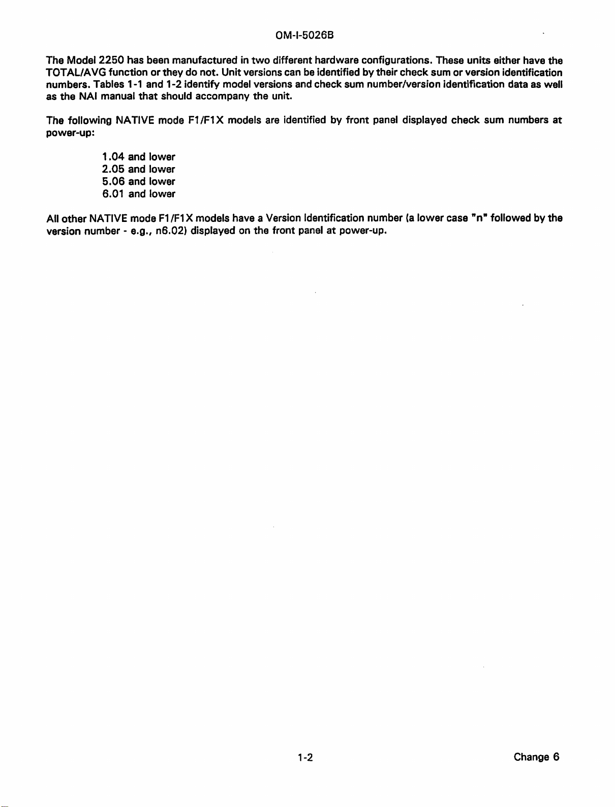
The Model
2250
has been manufactured in
two
different hardware configurations. These units either have the
TOT
AL/
AVG function
or
they do not. Unitversions can
be
identified
by
theircheck sum
or
version identification
numbers. Tables
1-1
and 1-2identify model versions
and
check sum number/version identification data
as
well
as
the NAI manual
that
should accompany the unit.
The following NATIVE mode
F1
/F1
X models
are
identified by
front
panel displayed check sum numbers
at
power-up:
1.04
and lower
2.05
and lower
5.06
and lower
6.01 and lower
All other NATIVE mode
F1
/F1
X models have a Version Identification number
(a
lower
case
"n"
followed bythe
version number -e.g., n6.02) displayed on the front panel
at
power-up.
1-2 Change 6
This manual suits for next models
1
Table of contents
Other North Atlantic Measuring Instrument manuals


Popular Measuring Instrument manuals by other brands


Greenlee
Greenlee CM-1360 instruction manual

Smart temp
Smart temp SMT-IAQ3 manual

CARLO GAVAZZI
CARLO GAVAZZI LDI 35 - CONFIGURATION SOFTWARE operating instructions

Michell Instruments
Michell Instruments QMA601 user manual

Endress+Hauser
Endress+Hauser Proline Promag W 400 HART operating instructions

Futech
Futech QUATTRO manual