North Atlantic 8810A User manual

Artisan Technology Group is your source for quality
new and certied-used/pre-owned equipment
• FAST SHIPPING AND
DELIVERY
• TENS OF THOUSANDS OF
IN-STOCK ITEMS
• EQUIPMENT DEMOS
• HUNDREDS OF
MANUFACTURERS
SUPPORTED
• LEASING/MONTHLY
RENTALS
• ITAR CERTIFIED
SECURE ASSET SOLUTIONS
SERVICE CENTER REPAIRS
Experienced engineers and technicians on staff
at our full-service, in-house repair center
WE BUY USED EQUIPMENT
Sell your excess, underutilized, and idle used equipment
We also offer credit for buy-backs and trade-ins
www.artisantg.com/WeBuyEquipment
REMOTE INSPECTION
Remotely inspect equipment before purchasing with
our interactive website at www.instraview.com
LOOKING FOR MORE INFORMATION?
Visit us on the web at www.artisantg.com for more
information on price quotations, drivers, technical
specications, manuals, and documentation
Contact us: (888) 88-SOURCE | sales@artisantg.com | www.artisantg.com
SM
View
Instra

Operations Manual for Model 8810A
ANGLE POSITION INDICATOR
TWO SYNCHRO/RESOLVER MEASUREMENT CHANNELS AND
ONE (OPTIONAL) REFERENCE SUPPLY
North Atlantic Industries, Inc.
631.567.1100 / 631.567.1823 (fax)
2/22/2019
8810A Operations Manual Rev P
110 Wilbur Place, Bohemia, NY 11716
www.naii.com
Cage Code: 0VGU1
Page 1 of 34
GENERAL
This Operations Manual contains general description, installation, operating instructions, maintenance and calibration
verification information for the Model 8810A Angle Position Indicator (API). This Operation Manual is supplemented by
“8810A Programmer’s Reference” which can be found at www.naii.com.
FEATURES
•High-Resolution Touch Screen
•Programmable display options
•Self-Calibrating
•0.0001° Resolution
•Accuracy: Up to ±0.0015°
•Two isolated Input Channels
•Single or Two-Speed Measurements:
Programmable Ratio from 2 to 255
•Three display modes: 0-360°, ±180° or
degrees, minutes & seconds
•Auto-ranging Signal and Reference
•47Hz to 20KHZ Frequency Range
•Auto Phase Correction
•Measures and displays Reference
Voltage, frequency, and VL-L
•Ethernet, USB, IEEE-488 & parallel ports
•Optional 6 VA internal Reference
•CE compliant
DESCRIPTION
The 8810A is a rack mount or bench top API featuring front panel controls (including touch screen display) and input terminals.
This self-calibrating unit is furnished with factory installed rubber feet and foldaway tilt stand and can also be installed in a
3.5” half rack slot. Using optional rack mounting brackets, the 8810A may be installed as a single unit in a full rack slot or as a
tandem mount of two units in a full rack slot.
This second-generation API truly represents a major step forward in Synchro-to-digital conversion technology. The use of an
intelligent DSP design eliminates push buttons and allows all programming to be done either via an integrated touch-screen, front
panel USB optical mouse interface or with the multi-purpose increment/setup knob. In addition, IEEE-488, Ethernet, and USB 2.0
interfaces have been added to extend remote operation capabilities. The display can be set for one of three display modes; 0-360º,
±180°, or Degrees, Minutes, Seconds. A wide frequency range (47 Hz to 20 KHz) is standard.
Improved flexibility is provided by two fully independent inputs that can be used to simultaneously read two separate input signals
or can be combined to measure multi-speed Synchro’s or Resolvers. The gear ratio, for the two-speed mode, is programmable from
2:1 to 255:1. Built-in phase correction eliminates errors caused by quadrature and harmonics when reference and signal are out of
phase by as much as 60°.
The 8810A automatically accepts and displays input voltages from 1.0VL-L to 90VL-L and reference voltages from 2Vrms to 15Vrms
over a broad frequency range of 47 Hz to 20 KHz. Therefore, one Instrument can handle most known Synchro and Resolver
measurement requirements.
The 8810A is a replacement for all variations of the previously supplied standard and special versions of the Model 8810. Contact
factory to determine compatibility.
Optional Reference: This design can also incorporate a 6 VA programmable reference generator that is used for standalone
applications (See P/N).

North Atlantic Industries, Inc.
631.567.1100 / 631.567.1823 (fax)
2/22/2019
8810A Operations Manual Rev P
110 Wilbur Place, Bohemia, NY 11716
www.naii.com
Cage Code: 0VGU1
Page 2 of 34
SPECIFICATIONS
Resolution: 0.0001°
Input Channels: 2 separate isolated Inputs
Signal Inputs: Ch.1: Synchro/Resolver programmable; 1 - 90VL-L auto-ranging
Ch.2: Synchro/Resolver programmable; 1 - 90VL-L auto-ranging
Each channel measures the Input VL-L, Reference voltage and frequency. Data is
displayed on the front panel and also available via various digital outputs.
Accuracy: See detailed Accuracy Specifications below.
Frequency Range: 47 Hz – 20 kHz. See detailed Accuracy Specifications below.
Angular Range: 0.0000°-359.9999° or ±179.9999° programmable, or output angle can be viewed in
degrees, minutes and seconds
Two-speed mode: Both inputs can be combined with a ratio from 2 to 255
Reference Voltage: 2V to 115 V auto-ranging
Reference Frequency: 47 Hz – 20 kHz
Input Impedance: Input Signal (V L-L) Input Impedance (kΩ)
1 to 3 V 47
3 to 6 V 55
6 to 11.8 V 58
11.8 to 26 V 60
26 to 90 V 200
Tracking Speed: ±10,000°/sec. (±27.7rps)
Settling Time: 1.5 s max. for 180° step change (Based on Bandwidth selected)
3.0 s max. at 47-66 Hz (Based on Bandwidth selected)
Phase Correction: Automatically corrects for up to a 60° phase shift between stator and rotor
Velocity or DC angle ±1000 °/sec = ±10 VDC
for Ch.1 & Ch.2: ±100 °/sec = ±10 VDC
0 to 359.99°= 0 -10 VDC
±179.99° = ±10 VDC
Bandwidth: Automatically set based on frequency of input, up to a max of 100 Hz BW. User can
change this parameter as desired, over a range of 6 to 1200 Hz BW. (See details under
Setup Menus).
Data averaging: Selectable from 10ms to 10 Seconds
Converter Busy: TTL compatible pulses, 1µs wide nom. Pulses present when tracking.
Digital Output: 6-Decade BCD (1-2-4-8) 10 TTL loads
Serial Interfaces: Ethernet, USB, and IEEE-488, and legacy 50 pin connector
Temperature Range: 0-50°C operating; 0-70°C storage
Input Power: 85Vrms to 265Vrms, 47Hz to 440 Hz, < 20 Watts
Weight: 4 lbs.
Dimensions: 13.0” L (33.02 cm) x 9.5” W (24.13 cm) x 3.5” H (8.89 cm)
North Atlantic Industries, Inc.
631.567.1100 / 631.567.1823 (fax)
2/22/2019
8810A Operations Manual Rev P
110 Wilbur Place, Bohemia, NY 11716
www.naii.com
Cage Code: 0VGU1
Page 3 of 34
REFERENCE GENERATOR SPECIFICATIONS (Optional, see part number)
Voltage Output: 2 Vrms to 115 Vrms, Programmable with a resolution of 0.1 V
•2.0 to 10.0 Vrms / 47 Hz to 20 KHz frequency range
•10.1 to 28.0 Vrms / 47 Hz to 10 KHz frequency range
•28.1 to 115.0 Vrms / 47 Hz to 2.5 KHz frequency range
Accuracy (No Load): ±5% of setting < 15 KHz
±10% of setting ≥15 KHz
Regulation ±5% (No Load to Full Load)
Output Drive: 6 VA maximum (See detailed description of Output Drive)
Output Protection: Over-current (10x automatic retry; @ 1.3 sec int.; afterwards, shutdown w/ manual reset)
Frequency: 47 Hz to 20 KHz Programmable with 0.1 Hz steps
Frequency accuracy: The greater of ±0.1% of frequency programmed or ±1 Hz.
THD: ±3% (maximum)
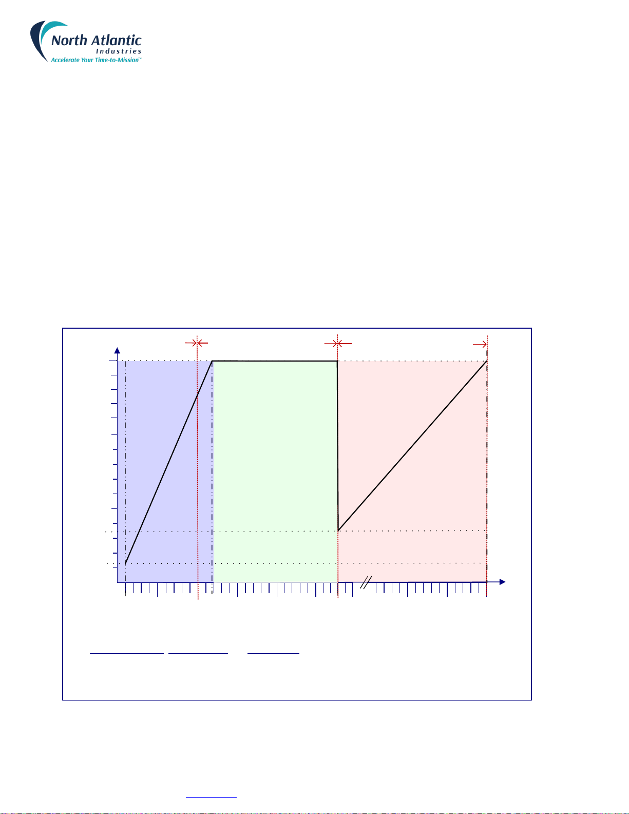
Reference Output Drive: Isolated, single output
(See detailed characterization)
Above figure: Reference output drive detailed characterization
Voltage(V)Output (Programmed)
Power Output (VA)
2.0
4.0
6.0
30
115
25
20
15
10
xx
Max Current ~ 508 mA Max Current ~ 52 mA
Power Derating Curves:
Voltage Range (Vrms)Max Current (mA)Power Derating
2 -11.9 508 6 VA @ 11.8 Vrms (Power derates linearly to 0.5 VA @ 2.0 Vrms)
12 -27.9 508 to 231 6 VA @ 26.0 Vrms (Power constant to 12.0 Vrms)
28 - 115 52 6 VA @ 115 Vrms (Power derates linearly to 1.4 VA @ 28.0 Vrms)
xx
5
2 - 10 V Frequency Range: 47 – 20000 Hz 10.1 – 28 V Frequency Range: 47 – 10000 Hz 28.1 – 115 V Frequency Range: 47 – 2500 Hz
6VA Power Constant
Max Current ~ 508mA to 231 mA
(w/ voltage inversely proportional)
0.5
1.4
North Atlantic Industries, Inc.
631.567.1100 / 631.567.1823 (fax)
2/22/2019
8810A Operations Manual Rev P
110 Wilbur Place, Bohemia, NY 11716
www.naii.com
Cage Code: 0VGU1
Page 4 of 34
DETAILED ACCURACY SPECIFICATIONS
NOTE: SPECIFICATIONS APPLY AFTER A 15 MINUTE WARMUP AND CALIBRATION
Accuracy: 8810A
Resolver mode: 2.0 to 28 VL-L
±0.004° from 47 Hz to 5 KHz
Resolver mode: 28 to 90 VL-L
±0.004° from 47 Hz to 1 KHz
Resolver mode: 2.0 to 12 VL-L
±0.004° to ±0.008° from 5 KHz to 10 KHz derated linearly
Resolver mode: 2.0 to 12 V
L-L
±0.008° to ±0.015° from 10 KHz to 15 KHz derated linearly
Resolver mode: 2.0 to 12 V
L-L
±0.015° to ±0.02° from 15 KHz to 20 KHz derated linearly
Resolver mode: 1.0 to 2.0 VL-L
±0.006° from 47 Hz to 5 KHz
Resolver mode: 1.0 to 2.0 VL-L
±0.006° to ±0.015° from 5 KHz to 10 KHz derated linearly
Resolver mode: 1.0 to 2.0 VL-L
±0.015° to ±0.025° from 10 KHz to 15 KHz derated linearly
Resolver mode: 1.0 to 2.0 VL-L
±0.025° to ±0.035° from 15 KHz to 20 KHz derated linearly
Synchro mode: 2.0 to 90 V
L-L
±0.004° from 47 Hz to 1 KHz
Accuracy: 8810AH
Resolver mode: 2.0 to 28 V
L-L
±0.0015° from 47 Hz to 5 KHz
Resolver mode: 28 to 90 VL-L
±0.002° from 47 Hz to 1 KHz
Resolver mode: 2.0 to 12 V
L-L
±0.0015° to ±0.005° from 5 KHz to 10 KHz derated linearly
Resolver mode: 2.0 to 12 V
L-L
±0.005° to ±0.01° from 10 KHz to 15 KHz derated linearly
Resolver mode: 2.0 to 12 VL-L
±0.010° to ±0.015° from 15 KHz to 20 KHz derated linearly
Resolver mode: 1.0 to 2.0 VL-L
±0.0025° from 47Hz to 5 KHz
Resolver mode: 1.0 to 2.0 VL-L
±0.0025° to ±0.01° from 5KHz to 10 KHz derated linearly
Resolver mode: 1.0 to 2.0 VL-L
±0.010° to ±0.02° from 10 KHz to 15 KHz derated linearly
Resolver mode: 1.0 to 2.0 VL-L
±0.02° to ±0.03° from 15 KHz to 20 KHz derated linearly
Synchro mode: 2.0 to 28 V
L-L
±0.0015° from 47 Hz to 1 KHz
Synchro mode: 28 to 90 VL-L
±0.0025° from 47 Hz to 1 KHz

North Atlantic Industries, Inc.
631.567.1100 / 631.567.1823 (fax)
2/22/2019
8810A Operations Manual Rev P
110 Wilbur Place, Bohemia, NY 11716
www.naii.com
Cage Code: 0VGU1
Page 5 of 34
TABLE OF CONTENTS
FEATURES ................................................................................................................................................................ 1
DESCRIPTION........................................................................................................................................................... 1
SPECIFICATIONS ..................................................................................................................................................... 2
REFERENCE GENERATOR SPECIFICATIONS (OPTIONAL,SEE PART NUMBER).................................................. 3
DETAILED ACCURACY SPECIFICATIONS ......................................................................................................... 4
TABLE OF CONTENTS ............................................................................................................................................ 5
SAFETY SUMMARY .................................................................................................................................................. 7
GENERAL SAFETY NOTICES .............................................................................................................................. 7
REPAIR ..............................................................................................................................................................................7
HIGH VOLTAGE .................................................................................................................................................................7
INPUT POWER ALWAYS ON ............................................................................................................................................7
INTERFACES............................................................................................................................................................. 8
J1 CONNECTOR, API PARALLEL PIN DESIGNATIONS ..................................................................................................8
J2 CONNECTOR, IEEE - 488 PIN DESIGNATIONS..........................................................................................................8
J3 CONNECTOR: ...............................................................................................................................................................8
•
USB-B (USB 2.0) Rear Connector, for communications only....................................................................................8
CONTROLS & INDICATORS GENERAL DESCRIPTION ....................................................................................... 9
CHANNEL SELECTION ............................................................................................................................................. 10
INTERNAL REFERENCE SETUP ................................................................................................................................ 11
SYNCHRO /RESOLVER MODE SELECT..................................................................................................................... 11
RATIO SELECT ....................................................................................................................................................... 12
ANGLE DIFFERENCE ............................................................................................................................................... 12
PROGRAMMING ..................................................................................................................................................... 13
REMOTE PROGRAMMING /LEGACY 8810 SUPPORT (REFER TO 8810A PROGRAMMER’S REFERENCE GUIDE) .............. 13
IEEE-488 ..........................................................................................................................................................................13
USB ..................................................................................................................................................................................13
Ethernet ............................................................................................................................................................................13
GENERAL PROGRAMMING /OPTIONS SELECTING ..................................................................................................... 13
USB Port Selection ...........................................................................................................................................................13
Ethernet Port Selection .....................................................................................................................................................14
SETUP MENUS ....................................................................................................................................................... 15
ORDERING INFORMATION .................................................................................................................................... 21
PART NUMBER: .......................................................................................... ERROR! BOOKMARK NOT DEFINED.
ACCESSORIES:.......................................................................................................ERROR!BOOKMARK NOT DEFINED.
OPTIONAL MOUNTING ACCESSORIES ......................................................................ERROR!BOOKMARK NOT DEFINED.
INSTALLATION AND MAINTENANCE .................................................................................................................. 22
UNPACKING AND INSPECTION ........................................................................................................................ 22
SHIPPING............................................................................................................................................................ 22
INSTALLATION ................................................................................................................................................... 22
Rack Mounting Instructions:..............................................................................................................................................22
Bench Installation:.............................................................................................................................................................22
MAINTENANCE................................................................................................................................................... 22
Input AC Power Fuse(s):...................................................................................................................................................22
Rear Panel Cooling Fan Filter:..........................................................................................................................................23
CALIBRATION ..................................................................................................................................................... 23
Calibration Verification......................................................................................................................................................23

North Atlantic Industries, Inc.
631.567.1100 / 631.567.1823 (fax)
2/22/2019
8810A Operations Manual Rev P
110 Wilbur Place, Bohemia, NY 11716
www.naii.com
Cage Code: 0VGU1
Page 6 of 34
APPENDIX A - MECHANICAL OUTLINE, MODEL 8810A .................................................................................... 24
APPENDIX B – SUPPLEMENTAL INFORMATION FOR UNITS SOLD WITHIN THE EUROPEAN UNION ....... 25
GENERAL............................................................................................................................................................ 25
SPECIFICATIONS ............................................................................................................................................... 25
Environmental...................................................................................................................................................................25
Fuses ................................................................................................................................................................................25
LINE CORD ......................................................................................................................................................... 25
INSTALLATION AND MAINS INPUT ................................................................................................................... 25
LINE VOLTAGE ................................................................................................................................................... 25
SAFETY GROUNDING........................................................................................................................................ 26
IMPROPER USAGE ............................................................................................................................................ 26
TECHNICAL ASSISTANCE................................................................................................................................. 26
APPENDIX C – 8810A SERIES DECLARATION OF CONFORMITY.................................................................... 27
APPENDIX D – INTERNAL CALIBRATION OPERATION ADDENDUM .............................................................. 28
APPENDIX E – 8810A NEW FEATURES OPERATION ADDENDUM .................................................................. 30
REVISION HISTORY................................................................................................................................................ 34
TABLE OF FIGURES
Figure 1 – Front Panel Controls & Connections ...........................................................................................................................9
Figure 2 – Indicators on the front panel main display of the 8810A............................................................................................10
Figure 3 – Channel Selection .....................................................................................................................................................10
Figure 4 – Internal Reference Setup ..........................................................................................................................................11
Figure 5 – Synchro / Resolver Mode Select ...............................................................................................................................11
Figure 6 – Ratio Select...............................................................................................................................................................12
Figure 7 – Angle Difference Select.............................................................................................................................................12
Figure 8 – Remote Operation .....................................................................................................................................................13
Figure 9 – USB Port Selection....................................................................................................................................................13
Figure 10 – Ethernet Port Selection ...........................................................................................................................................14
Figure 11 – IEEE-488 Port Selection..........................................................................................................................................14
Figure 12 – Setup Menus ...........................................................................................................................................................15
Figure 13 – Options Menu..........................................................................................................................................................15
Figure 14 – Factory Setting ........................................................................................................................................................16
Figure 15 – Custom Settings......................................................................................................................................................16
Figure 16 – Brightness Control ....................................................................................................................................................16
Figure 17 – Calibration Menu .....................................................................................................................................................17
Figure 18 – Help Menus .............................................................................................................................................................17
Figure 19 – Default Values.........................................................................................................................................................18
Figure 20 – D/A Setup................................................................................................................................................................18
Figure 21 – Bandwidth ...............................................................................................................................................................18
Figure 22 – Strip Chart Feature..................................................................................................................................................19
Figure 23 – Strip Chart Configuration Menu ...............................................................................................................................19
Figure 24 – Angle Averaging......................................................................................................................................................20
Figure 25 – Angle Limits & Thresholds.......................................................................................................................................20
North Atlantic Industries, Inc.
631.567.1100 / 631.567.1823 (fax)
2/22/2019
8810A Operations Manual Rev P
110 Wilbur Place, Bohemia, NY 11716
www.naii.com
Cage Code: 0VGU1
Page 7 of 34
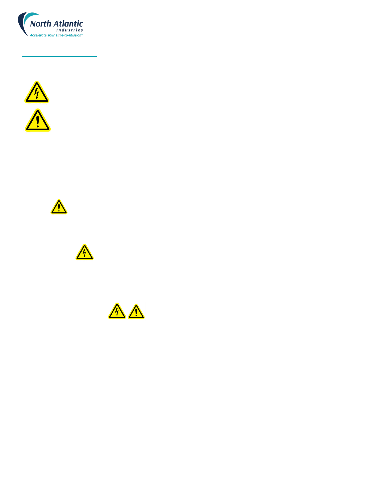
SAFETY SUMMARY
This symbol is intended to alert the presence of un-insulated dangerous voltage and shock hazard if
misuse or improper handling.
This symbol is intended to alert the presence of important information in the literature accompanying
this device. All information should be read carefully to avoid misuse and potential harm to the user
and/or device.
GENERAL SAFETY NOTICES
The following general safety notices supplement the specific warnings and cautions appearing elsewhere in the manual.
They are recommended precautions that must be understood and applied during operation and maintenance of the
instrument covered herein.
REPAIR
DO NOT ATTEMPT REPAIR. Under no circumstances should repair of energized instrument be attempted. All repairs
to this instrument must be accomplished at the Factory.
HIGH VOLTAGE
HIGH VOLTAGE is used in the operation of this equipment.
DEATH ON CONTACT may result if personnel fail to observe safety precautions. Learn the areas containing high
voltage on this equipment. Be careful not to contact high-voltage connections when installing, operating or maintaining
this instrument.
INPUT POWER ALWAYS ON
The design of the model 8810A is such that AC input power is continuously supplied to the power supply independent of
the front panel ON/OFF Switch. The primary means of disconnect is pulling the line cord from the instrument
WARNINGS

North Atlantic Industries, Inc.
631.567.1100 / 631.567.1823 (fax)
2/22/2019
8810A Operations Manual Rev P
110 Wilbur Place, Bohemia, NY 11716
www.naii.com
Cage Code: 0VGU1
Page 8 of 34
INTERFACES
The 8810A is available with several different interfaces for ATE applications. Interfaces include Ethernet, USB, IEEE-
488, and a legacy 50 pin connector for API parallel BCD outputs. Below is information, for each interface. Detail
programming commands / information are included in “8810A Programmer’s Reference Guide”.The Ethernet
connector and the USB connector, J3, are industry standard connections.
J1 CONNECTOR, API PARALLEL PIN DESIGNATIONS
DD50P, Mate DD50S or equivalent
Pin
Designation
Pin
Designation
1
Do Not Use(1)
26
R2 CH.2 REF LO Input
2
Do Not Use(1)
27
Not Data Freeze
3
Chassis ground
28
0.02º (BCD Output)
4
Digital ground
29
0.08º (BCD Output)
5
S1 CH.1 Resolver (Sin LO); Synchro (X)
30
0.1º (BCD Output)
6
S2 CH.1 Resolver (Cos HI); Synchro (Z)
31
0.4º (BCD Output)
7
S3 CH.1 Resolver (Sin HI); Synchro (Y)
32
2º (BCD Output)
8
S4 CH.1 Resolver (Cos LO)
33
8º (BCD Output)
9
R1 CH.1 REF HI Input
34
Not Used
10
R2 CH.1 REF LO Input
35
Not Used
11
Converter busy
36
Reference Output HI(3)
12
0.04º (BCD Output)
37
Reference Output LO(3)
13
0.01º (BCD Output)
38
0.008º (BCD Output)
14
0.8º (BCD Output)
39
0.002º (BCD Output)
15
0.2º (BCD Output)
40
0.001º or 0.005º for 179.99º
16
4º (BCD Output)
41
DC out Ch.1(2)
17
1º (BCD Output)
42
Data Freeze
18
Not Used
43
Remote Ch. select
19
DC out Ch.2(2)
44
0.004º or 0.005º for
20
Local/Rem select
45
20 deg. (BCD Output)
21
S1 CH.2 Resolver (Sin LO); Synchro (X)
46
40 deg. (BCD Output)
22
S2 CH.2 Resolver (Cos HI); Synchro (Z)
47
80 deg. (BCD Output)
23
S3 CH.2 Resolver (Sin HI); Synchro (Y)
48
10 deg. (BCD Output)
24
S4 CH.2 Resolver (Cos LO)
49
100 deg. (BCD Output)
25
R1 CH.2 REF Hi Input
50
200º or + bit for 179.9º
Notes:
1- Previous models allowed power input at pins 1 & 2. To meet new safety requirements, power input is ONLY via the Power
Entry module.
2- DC outputs on pins 19 & 41 are referenced to pin 4, digital ground.
3- Only Available with selected Internal Reference Generator option.
J2 CONNECTOR, IEEE - 488 PIN DESIGNATIONS
Standard IEEE Interface Connector
Pin
Designation
Pin
Designation
Pin
Designation
Pin
Designation
1
DIO1
7
NRFD
13
DIO5
19
Gnd., NRFD
2
DIO2
8
NDAC
14
DIO6
20
Gnd., NDAC
3
DIO3
9
IFC
15
DIO7
21
Gnd., IFC
4
DIO4
10
SRQ
16
DIO8
22
Gnd., SRQ
5
EOI
11
ATN
17
REN
23
Gnd., ATN
6
DAV
12
Shield
18
Gnd., DAV
24
Gnd., Logic
J3 CONNECTOR:
•USB-B (USB 2.0) Rear Connector, for communications only
•Ethernet (10/100/1000 Base-T copper)

North Atlantic Industries, Inc.
631.567.1100 / 631.567.1823 (fax)
2/22/2019
8810A Operations Manual Rev P
110 Wilbur Place, Bohemia, NY 11716
www.naii.com
Cage Code: 0VGU1
Page 9 of 34
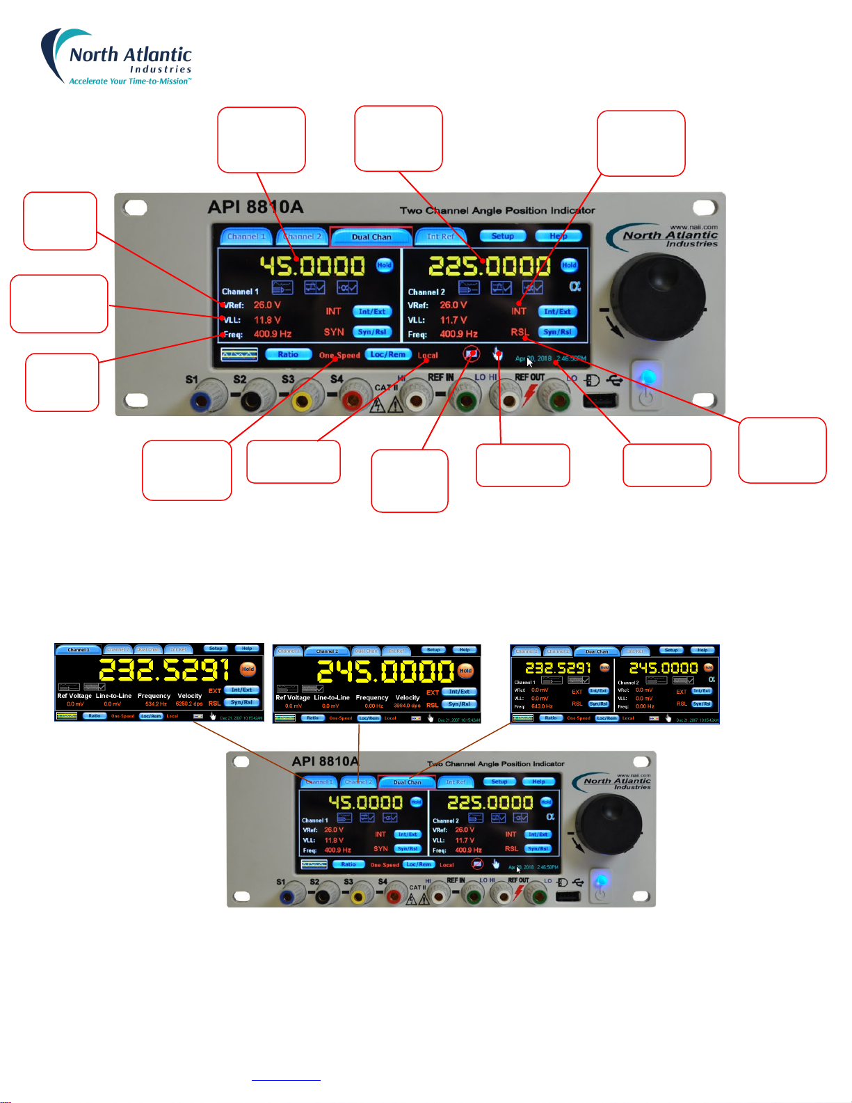
CONTROLS &INDICATORS GENERAL DESCRIPTION
Below is a general description of the Controls and Connections on the front panel main display of the 8810A.
Figure 1 – Front Panel Controls & Connections
Channel Select
Tabs
Internal
Reference
Setup
Setup Menu
Help Menu
Track & Hold
Display
Increment
Select Knob
Internal
External
Reference
Select
Synchro
Resolver
Mode
Select
Main
Power
Button
USB Port for
Optical
Mouse (only)
Internal
Reference
Output
External
Reference
Input
Channel One
Front/Back
Input Select
Touchscreen
Enable
Disable
Select
Synchro Resolver
Inputs
Angle
Averaging
View
Angle
Limits
Views
Strip
Chart
View
Channel Ratio
Configuration
Local / Remote
Select
North Atlantic Industries, Inc.
631.567.1100 / 631.567.1823 (fax)
2/22/2019
8810A Operations Manual Rev P
110 Wilbur Place, Bohemia, NY 11716
www.naii.com
Cage Code: 0VGU1
Page 10 of 34
Figure 2 – Front Panel Indicators
Channel Selection
To select channel 1, channel 2 or dual channel mode, select corresponding tab by using either the touch screen, mouse
or increment/setup knob. Below shows each channel select button along with the corresponding channel display.
Figure 3 – Channel Selection
Reference
Voltage
Display
Multi-Speed
Ratio
Indicator
Signal
Voltage (VLL)
Display
Reference
Frequency
Display
Local / Remote
Indicator
CH.1 Input
from Rear
Connector
Touch Screen
Enable
Time & Date
Display
Synchro
Resolver
Indicator
Reference
Source
Display
CH. 1 Main
Angle
Display
CH. 2 Main
Angle
Display

North Atlantic Industries, Inc.
631.567.1100 / 631.567.1823 (fax)
2/22/2019
8810A Operations Manual Rev P
110 Wilbur Place, Bohemia, NY 11716
www.naii.com
Cage Code: 0VGU1
Page 11 of 34
Internal Reference Setup
If internal reference option is installed in the 8810A; on the main screen, select the Int Ref button and the
setup screen for the internal reference will be displayed as shown below:
Figure 4 – Internal Reference Setup
Set the internal reference generator voltage and frequency parameters, using the setup screens shown above.
When done, press any of the channel buttons or any other function to exit this setup menu.
To enable output of the optional on-board reference source, insure the “Ref Out Signal:” displays “Available”.
Note: To turn on internal reference, ensure that the Int/Ext button located on any of the channel
displays is toggled on. Reference source indicator will display Int.
Synchro / Resolver Mode Select
On any channel screen, toggle the Syn/Rsl button to select either the Synchro or the Resolver mode.
The mode which is selected, will be displayed next to the button as shown below
Figure 5 – Synchro / Resolver Mode Select
North Atlantic Industries, Inc.
631.567.1100 / 631.567.1823 (fax)
2/22/2019
8810A Operations Manual Rev P
110 Wilbur Place, Bohemia, NY 11716
www.naii.com
Cage Code: 0VGU1
Page 12 of 34
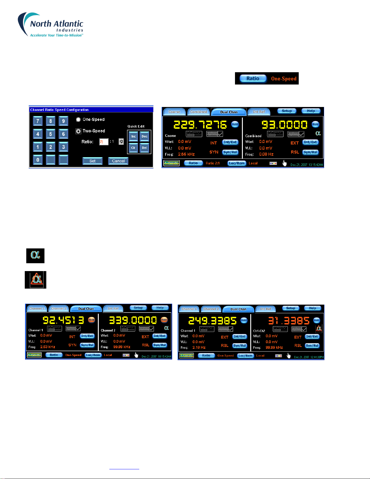
Ratio Select
The two inputs on the 8810A can be combined with a ratio of 2 to 255.
To enter the ratio menu and select the combined ratio, select the Ratio button and the menu
shown below will be displayed
Figure 6 – Ratio Select
Refer to the menu displayed above left. Select Two-Speed and enter the desired ratio from 2 to 255. Value may be
entered via keypad or with the Increment / Decrement buttons. Values may also be cleared or deleted using the quick
edit keypad. Once value is selected, hit Set button and unit will return to the channel display. Refer to the display to the
right and note that the ratio which has been set is now displayed next to the Ratio button. Also note that the channel
select tabs at the top have now changed from Channel 1 to Course and Channel 2 to Combined.
Angle Difference
The Channel 2 input signal is shown on the 8810A when the angle difference mode is disabled. The angle
data value is displayed in yellow.
The difference between two inputs on the 8810A can be displayed when the angle difference mode is
enabled. The angle difference is displayed in red.
Figure 7 – Angle Difference Select

North Atlantic Industries, Inc.
631.567.1100 / 631.567.1823 (fax)
2/22/2019
8810A Operations Manual Rev P
110 Wilbur Place, Bohemia, NY 11716
www.naii.com
Cage Code: 0VGU1
Page 13 of 34
PROGRAMMING
Remote programming / Legacy 8810 support (refer to 8810A Programmer’s Reference Guide)
IEEE-488
Language support is provided for the following legacy 8810 instrument features: (No language support for MATE/CIIL)
API-8810 Native
API-8810 SR103
API-8810 HSR202
API-8810HSR203
API-8810A Native Language provides remote programmability for features available in the 8810A.
USB
API-8810A Native Language provides remote programmability for features available in the 8810A.
Ethernet
API-8810A Native Language provides remote programmability for features available in the 8810A.
Remote Operation Setup
Figure 8 – Remote Operation
General Programming / Options selecting
The 8810A may be remote programmed through a USB port, an Ethernet port, an IEEE-488 port or the J1 connector. The
main setup screen for remote programming is shown above. The sections below show the setup for each mode.
From any of the Channel Displays, select the Loc/Rem button to enter the remote configuration menu
as shown below. Select remote button, then select desired port.
USB Port Selection
Selection of the USB port is accomplished by simply selecting the USB button as shown below. Once entered, hit set
and unit returns to main display.
Figure 9 – USB Port Selection
Note: the USB is now displayed next to the Loc/Rem button

North Atlantic Industries, Inc.
631.567.1100 / 631.567.1823 (fax)
2/22/2019
8810A Operations Manual Rev P
110 Wilbur Place, Bohemia, NY 11716
www.naii.com
Cage Code: 0VGU1
Page 14 of 34
Ethernet Port Selection
Selection of the Ethernet port is accomplished by selecting the Ethernet address button as shown below, entering the
Ethernet configuration for your network. Once entered, hit set and unit returns to main display. Modification of the
Ethernet port is accomplished by selecting the Ethernet address button and entering a valid IP address, the Submask
and Gateway address for your Ethernet network. The Ethernet Port used by the 8810A is always Port 23.
Figure 10 – Ethernet Port Selection
IEEE-488 Port Selection
This section describes the operation and programming of the Model 8810A using the IEEE-STD 488-1978, Standard
Digital Interface for Programmable Instrumentation. Selection of the IEEE port is accomplished by selecting the IEEE
Address button as shown above and entering an address. Once entered hit set and unit goes back to main display
Figure 11 – IEEE-488 Port Selection
Note: ETHERNET is now displayed next to the Loc/Rem button
Note: IEEE Address is now displayed next to the Loc/Rem button
North Atlantic Industries, Inc.
631.567.1100 / 631.567.1823 (fax)
2/22/2019
8810A Operations Manual Rev P
110 Wilbur Place, Bohemia, NY 11716
www.naii.com
Cage Code: 0VGU1
Page 15 of 34
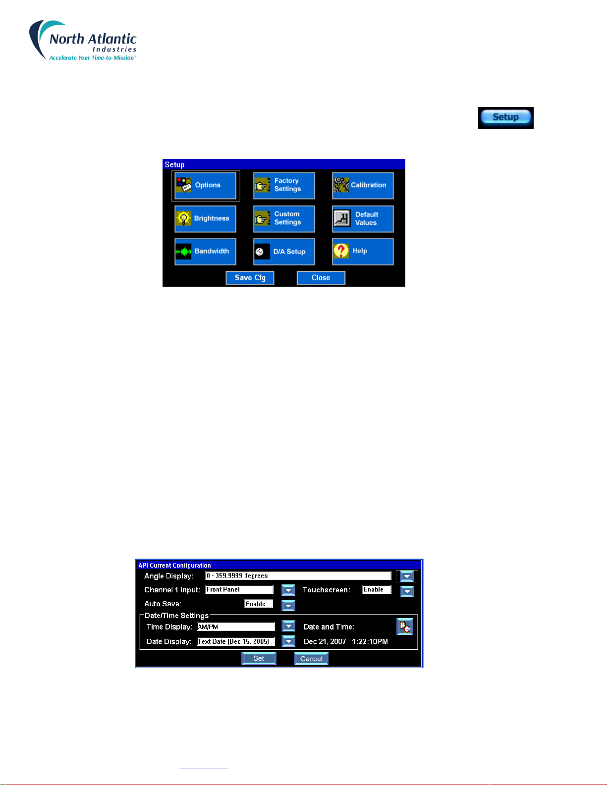
Setup Menus
The 8810A setup menu accesses many of the features of the API and allows the user to easily configure it through the
front panel. The setup menu is accessed by pressing the Setup button at the top of the main
display screen. As shown by the screen below, there are ten choices in the setup menu. The
section below describes each setup menu option.
Figure 12 – Setup Menus
A sample of the Options Menu is shown below. This menu allows configuration of the following:
•Angle Display may be configured for the following parameters
o0 to 359.9999 degrees
o-179.9999 to 179.9999 degrees
oDegrees, Minutes and Seconds
•Channel 1 Input may be configured for the following parameters
oFront Panel Input
oBack Connector Input (J1)
•Touch screen
oEnabled
oDisabled (re-enable using the Increment /Setup knob or mouse to select Options menu)
•Auto Save (feature available on non-revision B units)
oEnabled – 8810A will automatic save the 8810A configuration when the user changes the configuration
from the front panel or remotely.
oDisabled
•Date/Time Settings may be configured for the following parameters
oTime Display Format either AM/PM or Military
oDate Display Format either Text Date or Numeric only Date
oSetting of Time and Date
Figure 13 – Options Menu
North Atlantic Industries, Inc.
631.567.1100 / 631.567.1823 (fax)
2/22/2019
8810A Operations Manual Rev P
110 Wilbur Place, Bohemia, NY 11716
www.naii.com
Cage Code: 0VGU1
Page 16 of 34
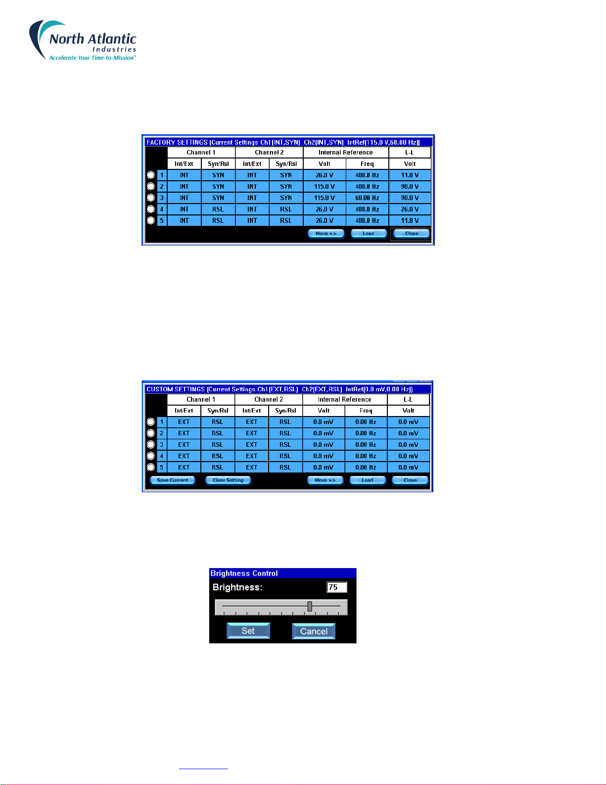
A sample of the Factory Setting screen is shown below. Factory settings contain 10 sets of parameters that are
permanently configured at the factory. These parameters include the settings for reference source, reference voltage,
reference frequency and Synchro / Resolver configuration. The pre-set parameter is chosen by simply selecting the
button on the left, followed by the Load button. Once completed, the API will return to the main display screen and the
values are stored until changed. Settings 1 through 5 are shown below. Select “More>>” to see 6 through 10.
Figure 14 – Factory Setting
A sample of the Custom Settings Screen is shown below. The 8810A also contains the ability for the user to assign up
to 10 custom configurations. These parameters include the settings for reference source, reference voltage, reference
frequency and Synchro / Resolver configuration. Custom parameters are set by saving current parameters which have
been previously set up on the main screens and then saving them to the 10 custom settings. This is accomplished by
selecting the button to the left to choose the number 1 – 10 line and then selecting the Save Current button. The
previously saved parameter is then chosen by selecting the button on the left, followed by the Load button. Settings 1
through 5 are shown above. Select “More>>” to see 6 through 10.
Figure 15 – Custom Settings
A sample of the Brightness Control screen is shown below. Brightness of the display is adjusted from 0 to 100% by
touching the scale bar until the desired brightness percentage is obtained. Note that the brightness value is displayed
above the bar.
Figure 16 – Brightness Control

North Atlantic Industries, Inc.
631.567.1100 / 631.567.1823 (fax)
2/22/2019
8810A Operations Manual Rev P
110 Wilbur Place, Bohemia, NY 11716
www.naii.com
Cage Code: 0VGU1
Page 17 of 34
Shown below is the main Calibration Menu screen which contains a calibration routine for the Touchscreen display and
a calibration routine for the measurement circuitry of the 8810A.
The Touchscreen Calibration will give prompts for the user to touch the screen in two places. The Touchscreen
calibration calibrates the “user’s touch” calibrating the touchscreen input position with the displayed content. When
completed and successful, it will display “Calibration Complete”.
The Unit Calibration will start an internal circuit calibration which requires no user intervention or external equipment.
The unit will commence a full (off-line) calibration of all ranges (as opposed to background calibration which is
continually running and calibrates the unit seamlessly while the unit is on-line at the particular voltage/frequency the unit
is currently operating). Unit Calibration takes approximately 4 minutes to complete and will display “Calibration
Completed” after successful completion.
Figure 17 – Calibration Menu
Shown above are examples of the Help Menu screens. The help menu gives things such as specification summaries,
descriptions of available buttons and descriptions of available functions included with the 8810A. The Help Menu screen
shows the unit’s serial number, date code, MAC address, model information and firmware revision.
Figure 18 – Help Menus

North Atlantic Industries, Inc.
631.567.1100 / 631.567.1823 (fax)
2/22/2019
8810A Operations Manual Rev P
110 Wilbur Place, Bohemia, NY 11716
www.naii.com
Cage Code: 0VGU1
Page 18 of 34
Default Values screen allow for restoring the 8810A to factory settings.
Figure 19 – Default Values
Each channel (0-360° or ±180° display mode only) can be independently set to provide a DC voltage representation of
either angular position (Vdc/degree) or angular velocity (Deg./Sec.). The D/A output range can be set to +/- 10 Vdc
max. See example below in Figure 20.
Figure 20 – D/A Setup
Two options are provided for setting the Bandwidth (BW) characteristics for each channel. As shown below, “Auto-
Bandwidth” or user preferred BW selection is possible as follows:
Auto-Bandwidth – The 8810A measures the reference frequency and then sets the BW to 12.5% of the ref. frequency.
The calculated BW will not exceed 100 Hz or be set below 6 Hz. This setting is the optimum for best compromise
between response / settling time and stability (Jitter of the lower LSB’s.) When this mode is selected the display
indicates the calculated BW setting in the BW Value window.
User Selected – The Auto-Bandwidth box unchecked allows the user to select the BW over the range of 6 to 1200 Hz.
It is recommended that BW not exceed 12.5% of the carrier frequency.
Figure 21 – Bandwidth

North Atlantic Industries, Inc.
631.567.1100 / 631.567.1823 (fax)
2/22/2019
8810A Operations Manual Rev P
110 Wilbur Place, Bohemia, NY 11716
www.naii.com
Cage Code: 0VGU1
Page 19 of 34
The 8810A includes a built-in strip chart feature which displays the angle readings in the form of a strip chart. Below is
a sample of the screen displayed
Figure 22 – Strip Chart Feature
The configure menu is shown in Figure 23. This menu allows the strip chart to be configured for the following
parameters:
•Data plotted as either angle, angle error or velocity
•Display of either channel 1, channel 2 or both channels
•Sampling rate (minimum 100 milliseconds, maximum 30 minutes)
•Upper and lower range
Figure 23 – Strip Chart Configuration Menu
The 8810A has a feature which allows Averaging of the Angle Readings. To access this feature select the angle
averaging button on the main display (shown below left). The averaging period may be set from 10 msec to 10 sec. The
number of angle readings which will be averaged is dependent on the rate of change of the angular data being
monitored. These values may be set by using the keypad or the knob shown above.
Other manuals for 8810A
1
Table of contents
Other North Atlantic Measuring Instrument manuals


Popular Measuring Instrument manuals by other brands

Precision Digital Corporation
Precision Digital Corporation Helios PD2-6300 instruction manual

BIRD
BIRD SiteHawk SK-6000 Operation manual

Total Control Systems
Total Control Systems 700-20 Engineering manual

Aalborg
Aalborg GFM 17 operating manual

Voltex
Voltex AMP operating manual

Tobi
Tobi PI Wi-Z Quick installation guide


