Northern Industrial Tools 486910 User manual
STEEL SPRING-DRIVEN REEL
OWNER’S MANUAL
WARNING: Read carefully and understand all
INSTRUCTIONS before operating. Failure to follow the safety
rules and other basic safety precautions may result in serious
personal injury.
Item# 486910
Page 2 of 9
Thank you very much for choosing a NORTHERN TOOL + EQUIPMENT CO., INC. Product! For future
reference, please complete the owner’s record below:
Model: _______________ Purchase Date: _______________
Save the receipt, warranty and these instructions. It is important that you read the entire manual to
become familiar with this product before you begin using it.
This machine is designed for certain applications only. Northern Tool + Equipment cannot be
responsible for issues arising from modification. We strongly recommend this machine is not modified
and/or used for any application other than that for which it was designed. If you have any questions
relative to a particular application, DO NOT use the machine until you have first contacted Northern
Tool + Equipment to determine if it can or should be performed on the product.
For technical questions please call 1-800-222-5381.
INTENDED USE
This steel spring-driven reel can be used to transfer air or water under max. pressure of 300 PSI.
This manual is applicable to the following reel only.
TECHNICAL SPECIFICATIONS
Item No.
468910
Working Pressure
Max. 300 PSI
Working Temperature
Max. 210°F
Hose Capacity
3/8" x 33'
Inlet/Outlet connection
3/8" NPT
General Safety Regulations
WARNING: Read and understand all instructions. Failure to follow all instructions listed
below may result in electric shock, fire and/or serious injury.
WARNING: The warnings, cautions, and instructions discussed in this instruction
manual cannot cover all possible conditions or situations that could occur. It must be understood
by the operator that common sense and caution are factors which cannot be built into this product, but
must be supplied by the operator.

Page 3 of 9
SAVE THESE INSTRUCTIONS
WORK AREA
åKeep work area clean, free of clutter and well lit. Cluttered and dark work areas can cause
accidents.
åDo not use your hose reel where there is a risk of causing a fire or an explosion; e.g. in
the presence of flammable liquids, gasses, or dust.
åKeep children and bystanders away while operating hose reel. Distractions can cause you to
lose control, so visitors should remain at a safe distance from the work area.
åBe aware of all power lines, electrical circuits, water pipes and other mechanical hazards in
your work area, particularly those hazards below the work surface hidden from the operator’s
view that may be unintentionally contacted and may cause personal harm or property damage.
åBe alert of your surroundings. Using air-powered tools in confined work areas may put you
dangerously close to cutting tools and rotating parts.
PERSONAL SAFETY
åStay alert, watch what you are doing and use common sense when operating your hose reel.
Do not use your hose reel while you are tired or under the influence of drugs, alcohol or
medication. A moment of inattention may result in serious personal injury.
åDress properly. Do not wear loose clothing, dangling objects, or jewelry. Keep your hair,
clothing and gloves away from moving parts. Loose clothes, jewelry or long hair can be caught
in moving parts
åUse safety apparel and equipment. Use safety goggles or safety glasses with side shields
which comply with current national standards, or when needed, a face shield. This applies to all
persons in the work area. Also use non-skid safety shoes, hardhat, gloves, dust collection
systems, and hearing protection when appropriate.
åDo not overreach. Keep proper footing and balance at all times.
PNEUMATIC TOOL USE AND CARE
åDo not force tools while using hose reel. Tools do a better and safer job when used in the
manner for which they are designed. Plan your work, and use the correct tool for the job.
åNever use a tool with a malfunctioning switch. Any power tool that cannot be controlled with
the switch is dangerous and must be repaired by an authorized service representative before
using.
åDisconnect air supply from tools and place the switch in the locked or off position before
making any adjustments, changing accessories, or storing power tools. Such preventive safety
measures reduce the risk of starting the power tool accidentally.
åSecure work with clamps or a vise instead of your hand to hold work when practical. This
safety precaution allows for proper tool operation using both hands.
åStore idle tools. When tools are not is use, store them in a dry, secure place out of the reach
of children. Inspect tools for good working condition prior to storage and before re-use with this
hose reel.
åKeep guards in place and in working order.
åNever leave tools running unattended while attached to this hose reel.
Page 4 of 9
åCompressed air only. Only use clean, dry and regulated compressed air at no more than 300
PSI with this hose reel. Never use oxygen, carbon dioxide or any other bottled gas as a power
source.
åUse proper size and type air pressure line and fittings. The recommended air line for this tool
is 3/8" delivering no more than 300 PSI. The air inlet size for this hose reel is 3/8".
åMake sure the hose is free of obstructions or snags. Entangled hoses can cause loss of
balance or footing.
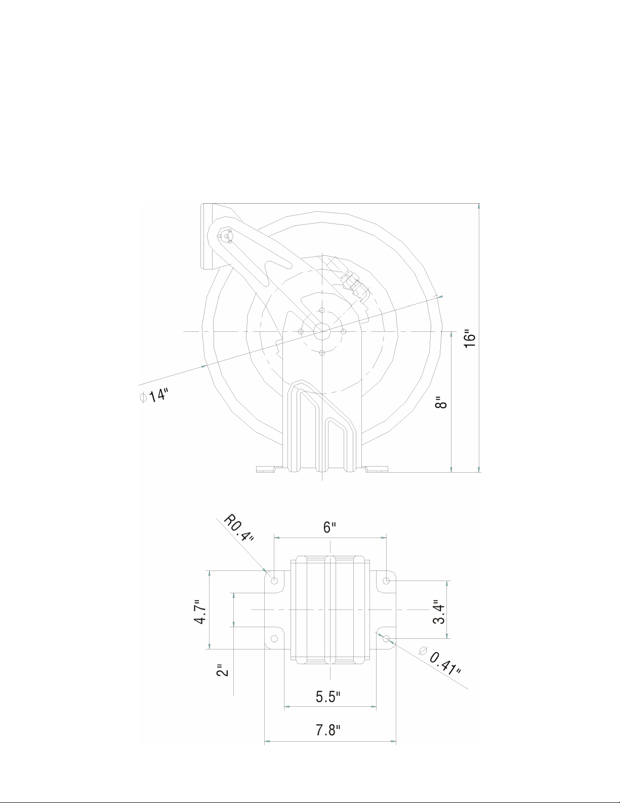
DIMENSIONS
Page 5 of 9
Personal Safety
WARNING: Personal injury and/or equipment damage may result if proper safety
precautions are not observed. Even low pressure is very dangerous and cause injury or death.
1. Ensure that reel is properly installed before connecting input and output hoses.
2. Bleed fluid/gas pressure from system before servicing reel.
3. Before connecting reel to supply line, ensure that pressure does not exceed maximum working
pressure rating of reel (300 PSI).
4. If a leak occurs in the hose or reel, remove system pressure immediately. Do not use until the hose
has been properly repaired.
5. If reel ceases to unwind or rewind, remove system pressure immediately. Do not pull or jerk on
hose.
Installation Instructions
1. Prior to mounting the hose reel, ensure that the supply line pressure does not exceed the maximum
working pressure of the hose reel.
2. Unpack and inspect the reel for damage.
3. Turn reel by hand to check for smooth operation. Check for complete components.
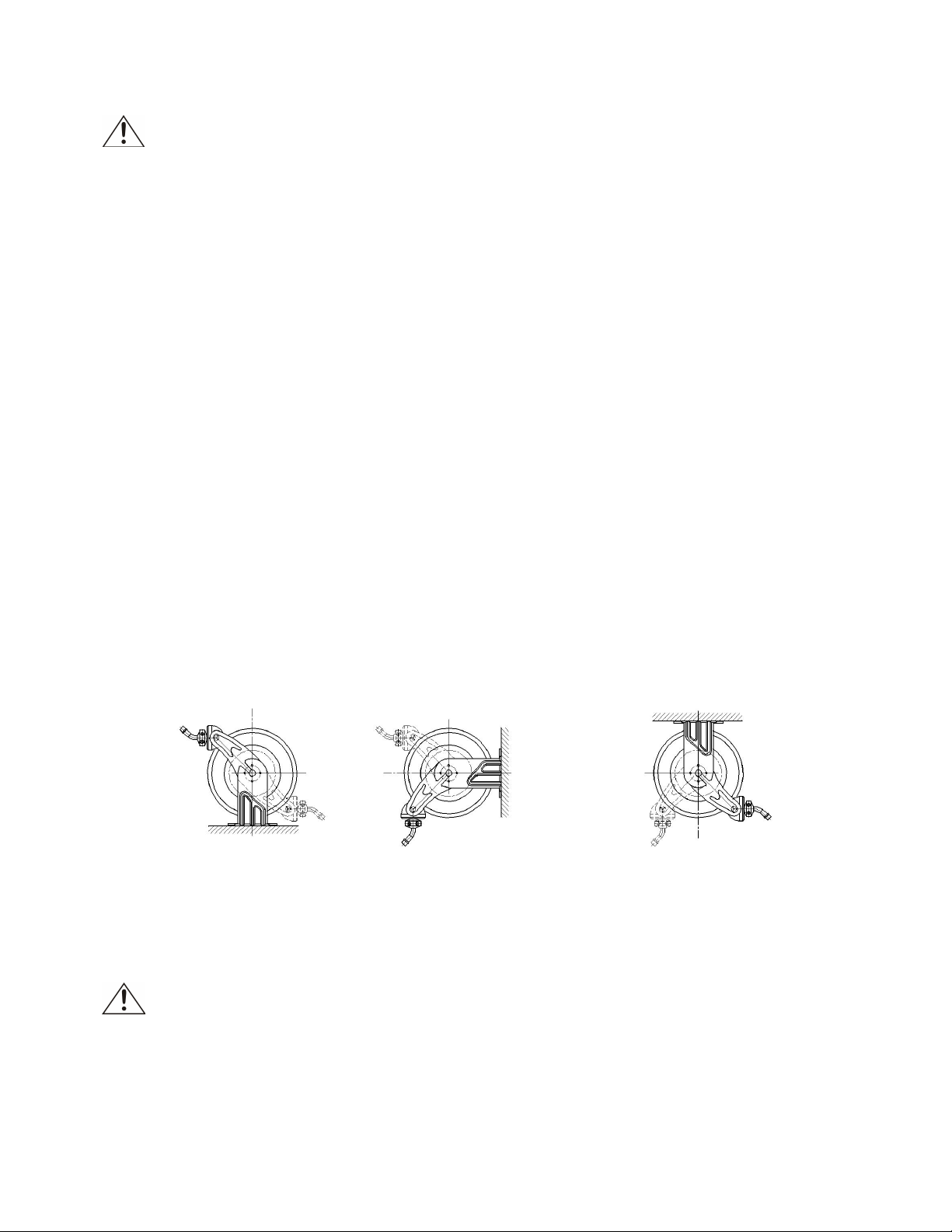
4. Position the reel on the floor, wall or ceiling. Secure into place using four mounting bolts (not
included) and installation template.
5. Depending on where the reel is placed, it may be necessary to adjust the hose bumper and guide
arm to use the hose properly. See the instructions below to adjust the hose bumper and the guide
arm.
ADJUSTING YOUR HOSE REEL
1. Adjusting spring tension
WARNING: Use extreme caution; reel under tension. Avoid releasing latch
mechanism.
If necessary, adjust spring tension on reel by adding or removing the hose from the spool, one wrap at
a time, until desired tension is obtained. Add hose to increase tension. Remove hose to decrease
tension.
Pull out the hose until the latch pawl is engaged. Loosen the hose bumper, then add wraps and
decrease the wraps until desired tension is achieved.
Table of contents
Other Northern Industrial Tools Tools manuals

Northern Industrial Tools
Northern Industrial Tools 816400 User manual

Northern Industrial Tools
Northern Industrial Tools 120203 User manual

Northern Industrial Tools
Northern Industrial Tools 148823 User manual

Northern Industrial Tools
Northern Industrial Tools 141805 User manual

Northern Industrial Tools
Northern Industrial Tools 159451 User manual


