Northern Telecom Meridian SL-1 User manual

© 1989 Northern Telecom
All right reserved.
NT, Meridian 1, Meridian and SL-1 are trademarks of Northern Telecom.
Title to and ownership of SL-1 software shall at all times remain with Northern Telecom. SL-1
software shall not be sold outright and the use thereof by the customer shall be subject to the
parties entering into agreement by Northern Telecom.
Information contained in this document is subject to change. Northern Telecom reserves the
right, without notice, to make changes in equipment or program components as progress in
engineering, manufacturing, or technology may warrant.
Installation and acceptance procedures 553-2931-200
SL-1
2-Mb Remote Peripheral Equipment
Installation and acceptance procedures
Publication number: 553-2931-200
Product release: Group F
Document status: Standard
Date: 90 11 02

Installation and acceptance procedures 553-2931-200
Reason for issue
90 11 02 Standard, Group F (Phase 6) - new Generic X11 Supplementary Feature

i of ipage
Installation and acceptance procedures 553-2931-200
Contents
General 1-1
Related documentation 1-1
Assembly and installation 2-1
Equipment handling and unpacking 2-1
Cabinet installation 2-1
RPE group installation 2-1
Equivalent packs 2-1
RPE group power 2-2
QBL14 power distribution box 2-2
RPE installation 2-2
Data administration implementation 2-19
Task - buffers/loops 2-19
Task - group member data 2-19
Task - timing threshold. 2-20
Task - counter threshold 2-21
Task - No-New-Data call timing 2-22
Acceptance tests 3-1
Carrier equipment tests 3-1
Loop-around tests 3-1
RPE group acceptance tests 3-2
Network loop tests 3-3
Telephone set, console, and add-on module tests 3-3
Customer defined alarm tests 3-3
Daily routines 3-4

1-1 of 1 page
Installation and acceptance procedures 553-2931-200
General
This Northern Telecom Publication (NTP) provides installation
procedures for the 2-Mb/s Remote Peripheral Equipment (RPE) feature
and acceptance tests required by the SL-1 Generic X11 Supplementary
Features, Group F (Phase 6).
Refer to NTP 553-2931-100 for feature and equipment descriptions as
well as for engineering guidelines. NTP 553-2931-500 provides fault-
clearing and maintenance information. Also refer to Appendix 1 to 553-
2741-100/200/500 for RPE cabinets and shelves for the ST and SN
machines.
Related documentation
Maintenance. Diagnostic program descriptions and input/output
references are provided in NTP 553-2301-511.
Data administration. Information and detailed procedures on feature
and service implementation are provided in NTP Appendix 1 to 553-
2311-311.
Description. Refer to NTP 553-2931-100 for feature and equipment
descriptions.
Fault-clearing. NTP 553-2931-500 provides fault-clearing and
maintenance information.
ST, SN machines. Refer to Appendix 1 to 553-2741-100/200/500 for
RPE cabinets and shelves.

2-1 of 22 pages
Installation and acceptance procedures 553-2931-200
Assembly and installation
The 2-Mb/s Remote Peripheral Equipment (RPE) may be shipped fully
assembled in cabinets; or shelves and circuit packs may be shipped
individually for installation in existing cabinets.
Equipment handling and unpacking
Before starting the installation refer to 553-YYY1-210 for instructions
regarding the procedures for unpacking and handling of equipment.
Cabinet installation
If new cabinets are to be installed refer to 553-YYY1-210 for cabinet
installation procedures. Refer to 553-2741-200 Appendix 1 for RPE
cabinets at a remote site for ST or SN machines.
RPE group installation
RPE shelves in local or remote sites are located in any cabinet location
that would normally house a Peripheral Equipment (PE) shelf. The
local site RPE shelf must be located within 50 cable feet (15 m) of any
connected network circuit packs. At the remote site the RPE shelf must
be within 50 cable feet (15 m) of any connected PE shelves. Refer to
553-2741-200 Appendix 1 for RPE shelves for ST or SN machines.
One RPE shelf pair (local and remote shelf) can have a maximum of
four network loops assigned to it. Each RPE shelf pair is defined as an
RPE group. The installation procedures are detailed in Procedures 2-1
and 2-2.
Equivalent packs
The equivalent NT and TELI (Sweden) packs are as shown in Table 2-1.

2-2 Assembly and installation
Installation and acceptance procedures 553-2931-200
Table 2-1
NT and TELI (Sweden) packs
NT TELI (Sweden)
QPC319 TPC24
QPC320 TPC25
QPC321 TPC29
QPC322 TPC26
RPE group power
QBL14 power distribution box
Power is distributed to RPE shelves (QSD21/QSD22) via the QBL14
located in a cabinet. The QBL14 unit is required at both local and
remote sites.
RPE installation
Table 2-2
Installation/removal procedures
Title Number
Local Site RPE Installation 2-1
Remote Site RPE Installation 2-2
RPE Circuit Pack Installation 2-3
RPE Circuit Pack Removal 2-4
Procedure 2-1
Local site RPE installation
1.Unpack and inspect the shelf. Refer to 553-YYY1-210.

Assembly and installation 2-3
Installation and acceptance procedures 553-2931-200
2.Ensure that the proper terminating units are installed on the shelf
backplane. Refer to Table 2-3.
—continued—

2-4 Assembly and installation
Installation and acceptance procedures 553-2931-200
Procedure 2-1 (continued)
Local site RPE installation
3.Position the shelf in the cabinet and secure with the mounting screws
supplied. Refer to service order.
Note: The shelf must be within 50 cable feet (15m) of the assigned
network circuit packs.
4. Install one NE-A18QA cable from the shelf to each network circuit
pack served by the shelf. Refer to service order and Figure 2-1.
Note: Refer to Figure 2-3 when a left-hand, mount RPE shelf
(QSD22) is provided.
5. Connect two 75-ohm coaxial cables from RPE shelf to Line Terminal
Units (LTU) for each loop. Refer to service order and Figure 2-1.
Note: Computer grade 75 ohm coaxial cable should be used. This
cable is supplied by the customer and must have BNC connectors
supplied with the shelf attached.
6.Insert 5/12-V Converter circuit pack in shelf. Refer to Figure 2-2, and
to Procedure 2-3.
7.If there is no existing RPE shelves in the cabinet it is necessary to
install a QBL14 power distribution box. Refer to Figure 2-4.
8.Install power cable (supplied with RPE shelf); connecting from the shelf
to the QBL14 unit. Refer to Figure 2-4.
Note: At the QBL14 unit, fuses for shelves being installed should
be removed, and the associated switch set to OFF.
9.At the QBL14 unit, insert fuse and set switch for shelf to ON. Refer to
Figure 2-4.
10.Unpack, inspect and insert circuit packs in RPE shelf as directed by
the service order. Refer to 553-YYY1-210, Procedure 2-3, and
Figure 2-2.
11. Add related office data. Refer to service order and Data
Administration Implementation herein.

Assembly and installation 2-5
Installation and acceptance procedures 553-2931-200
Table 2-3
BUS terminating unit assignment
Code Location Quantity
QPC164*44 Local RPE shelf 2 per shelf
QPC164*45 Remote RPE shelf 2 per shelf
Where * indicates the bus terminating unit vintage such as A, B, C or D.

2-6 Assembly and installation
Installation and acceptance procedures 553-2931-200
Figure 2-1
Local end network loop and shelf cabling
Assembly and installation 2-7
Installation and acceptance procedures 553-2931-200
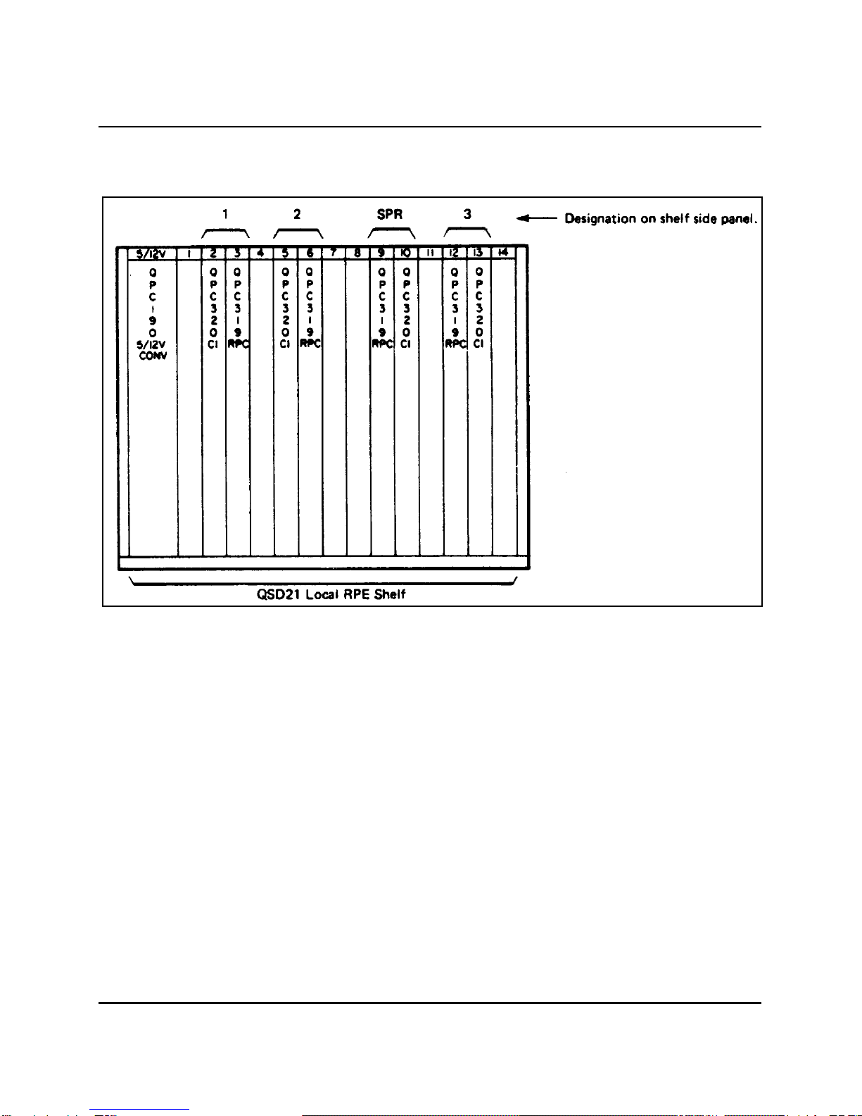
Figure 2-2
Local site circuit pack locations
2-8 Assembly and installation
Installation and acceptance procedures 553-2931-200
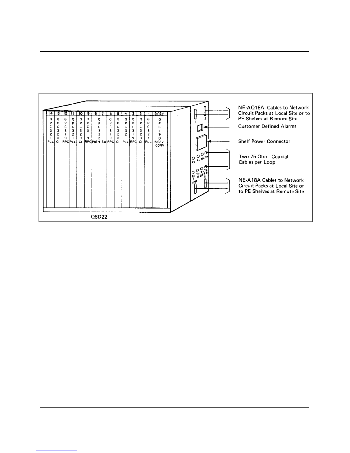
Figure 2-3
Typical layout of a left-hand mount RPE shelf (QSD22)
Assembly and installation 2-9
Installation and acceptance procedures 553-2931-200
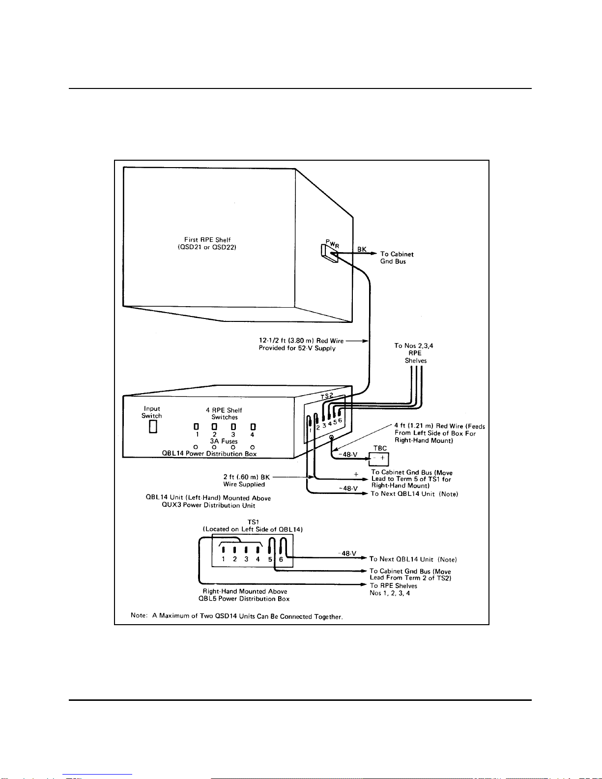
Figure 2-4
QBL14 power distribution box wiring and connections

2-10 Assembly and installation
Installation and acceptance procedures 553-2931-200
Procedure 2-2
Remote site RPE group installation
1. Unpack and inspect the shelf. Refer to 553-YYY1-210.
2.Ensure that the proper bus terminating units are installed on the
shelfbackplane. Refer to Table 2-3
3.Position the shelf in the cabinet and secure with mounting screws
supplied.
Note: The shelf must be within 50 cable feet (15 m) of all PE
shelves served.
4. Install an NE-A18QA cable from the RPE shelf connector to the first
PE shelf, connector F for each assigned loop.
Refer to Figures 2-5 and 2-10.
Note: Refer to Figure 2-3 when a left-hand mount RPE shelf
(QSD22) is provided.
5.Install NE-A18QA cables between PE shelves. Refer to Figure 2-5.
6. Install two 75-ohm coaxial cables for each loop from LTU to associated
Transmit (Tx) and Receive (Rx) connectors on the side of the RPE
shelf. Refer to Figures 2-5 and 2-10.
7. Install four NE-A25B type cables from jacks A, B, C and D of each PE
shelf to cross-connect terminal.
Refer to 553-YYY1-210 and to Figure 2-5.
8.Install alarm input cable if customer-defined alarms are required.
Refer to Figure 2-6.
9.Install power failure alarm. Refer to Figure 2-7.
10. If there are no existing RPE shelves in the cabinet it will be necessary
to install a QBL14 power distribution box. Refer to Figure 2-4.
11. Install the power cable (supplied with the RPE shelf); connecting it
from the QBL14 box to the RPE shelf. Refer to Figure 2-4.
Note: At QBL14 unit, fuses for shelves being installed should be
removed, and the associated switch set to OFF.

2-12 Assembly and installation
Installation and acceptance procedures 553-2931-200
Procedure 2-2 (continued)
Remote site RPE group installation
12. Install 5/12-V converter circuit pack in RPE shelf. Refer to Figure 2-8
and to Procedure 2-3.
13.At the QBL14 install fuses for RPE shelf and set shelf power switch to
ON. Refer to Figure 2-4.
14. Unpack, inspect and insert circuit packs into the RPE shelf as
directed by the service order. Refer to Figure 2-8, Procedure 2-3 and
service order.
15. Add related office data. Refer to Data Administration Implementation
herein, service order and Figure 2-10.

Assembly and installation 2-13
Installation and acceptance procedures 553-2931-200
Figure 2-5
Remote site RPE group cabling

2-14 Assembly and installation
Installation and acceptance procedures 553-2931-200
Figure 2-6
Alarm input lead connections
Note: A maximum of two Power Distribution Boxes can be connected together.

Assembly and installation 2-15
Installation and acceptance procedures 553-2931-200
Figure 2-7
Typical wiring connections for power failure alarm at remote site
2-16 Assembly and installation
Installation and acceptance procedures 553-2931-200
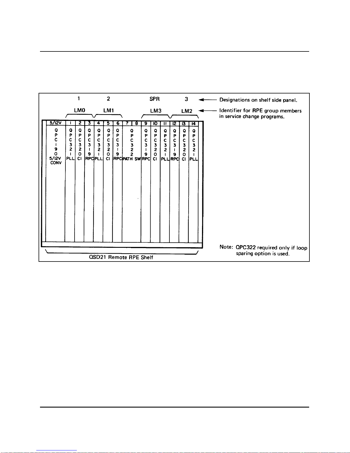
Figure 2-8
Remote site circuit pack locations

Assembly and installation 2-17
Installation and acceptance procedures 553-2931-200
Procedure 2-3
RPE circuit pack installation
CAUTION
Firmly touch the metal frame of the cabinet to discharge static
electricity from your body before handling circuit packs.
Note: Before installing an RPE circuit pack the loop that the
pack is assigned to should be replaced by the spare, if possible.
When the circuit pack has been replaced and testing is completed,
the loop should be enabled and placed back into service.
1.Remove the circuit pack from the shipping container.
Refer to 553-YYY1-210.
2.Add related office data from the service order into system memory, if
required. Refer to Data Administration Implementation herein, service
order, and Figure 2-10.
3. If the circuit pack has an ENB/DIS switch, set it to DIS before
inserting pack in shelf. Refer to Figure 2-9.
4. Insert the edges of the circuit pack in the upper and lower aligning
guides of the shelf. Ensure that pack is in correct location according
to service order. Refer to Figure 2-2, Figure 2-8, and service order.
5.Push the circuit pack until resistance is felt..
6.Use the locking devices to firmly engage the pack in the shelf
connector.
7.If equipped, set pack ENB/DIS switch to ENB.
8.Use the TTY, or maintenance set to software enable the circuit pack.
Refer to 553-2301-511 Program 53.
9.Test the circuit pack completely using overlay program 53.
Refer to 553-2301-511.
Other manuals for Meridian SL-1
3
This manual suits for next models
1
Table of contents
Other Northern Telecom PBX manuals


