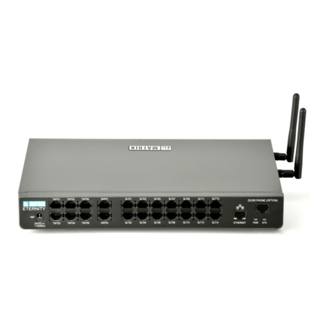
Northern Telecom Meridian SL-1 User manual

© 1988 Northern Telecom
All right reserved
NT, Meridian 1, Meridian and SL-1 are trademarks of Northern Telecom.
Title to and ownership of SL-1 software shall at all times remain with Northern Telecom. SL-1 software
shall not be sold outright and the use thereof by the customer shall be subject to the parties entering into
agreement as specified by Northern Telecom.
Information contained in this document is subject to change. Northern Telecom reserves the right,
without notice, to make changes in equipment or program components as progress in engineering,
manufacturing, or technology may warrant.
2 Mb/s DTI Fault Clearing Procedures 553-2911-510
SL-1
2-Mb/s Digital Trunk Interface
Fault clearing procedures
Publication number: 553-2911-510
Product release: Group F
Document status: Standard
Date: 91 03 08

553-2911-510 2 Mb/s DTI Fault Clearing Procedures
Reason for revision
91 03 08 This procedure was reissued to include information on the Japan Digital
Multiplex Interface (JDMI) for GenericX11 including supplementary
features.
It has been reformatted for CD-ROM application

i of i page
2 Mb/s DTI Fault Clearing Procedures 553-2911-510
Contents
General 1-1
Flowchart symbols 1-1
Trouble analyzing procedures 2-1
Alarm Lamps (LEDS) 2-1
Out of Service (OOS) Alarm LED Lit 2-1
Far-end Alarm (FEA) LED Lit 2-3
Near-end Alarm (NEA) LED Lit 2-6
Loopback Alarm LED Lit 2-9
Disable (DIS) Alarm LED Lit 2-11
Violation Error Messages 2-12
Slip Error Message 2-15
Frame Alignment Error Message 2-17
DTI2/DMI Pack Replacement 3-1
Clock Controller pack replacement 3-2
2.048 Megabit PCM line monitor 3-4
Verification tests for DTI2/DMI and CC packs 3-5

2 Mb/s DTI Fault Clearing Procedures 553-2911-510
General
This manual describes the maintenance procedures for the Meridian SL-
1
2 Mb/s Digital Trunk Interface (DTI) and Japan Digital Multiplex
Interface (JDMI) for GenericX11 including supplementary features.
This manual is divided into two chapters. The first chapter contains step-
by-step instructions on how to analyze a trouble. The second chapter
contains information and instructions on how to perform a specific task.
References are made in chapter one to the detailed procedures in
chapter two when required.
Flowchart symbols
Figure 1-1 illustrates the flowchart symbols contained in this manual.
Figure 1-1
Flowchart symbols
Instruction block - contains an instruction
[ 1]
Perform this
instruction or
operation.

1-2 General
2 Mb/s DTI Fault Clearing Procedures 553-2911-510
Figure 1-1 (continued)
Flowchart symbols
Decision block - contains a question. The answer indicates the
path to follow.
Yes
No
Answer this
question.
Yes or No?
[ 1]
Continuation symbol - contains the location of the next step
Step 5
Page 2
Stop symbol - identifies the end of a procedure

General 1-3
2 Mb/s DTI Fault Clearing Procedures 553-2911-510
Figure 1-1 (continued)
Flowchart symbols
AND symbol - groups a sequence of steps, ALL of which must be
performed to achieve a result.
Perform this
step, and
Perform this
step.
(1)
( 2 )
AND
OR symbol - groups a sequence of steps, only ONE of which
must be performed to achieve a result.
Perform this
step, or
Perform this
step.
(1)
( 2 )
OR

2-1 of 18 pages
2 Mb/s DTI Fault Clearing Procedures 553-2911-510
Trouble analyzing procedures
Alarm Lamps (LEDS)
This section contains detailed step-by-step instructions on how to
analyse a trouble (with reference to Detailed Procedures, where
required)
Out of Service (OOS) Alarm LED Lit
If either the Near-end alarm (NEA) or Far-end alarm (FEA) LED is also
lit, then perform that procedure (i.e., NEA or FEA) before attempting
this procedure.
[ 1]
[ 2]
Load overlay 60.
Check the DTI2
pack
Step 3
Page 2-2
DTI2 out of service
alarm LED is lit.

2-2 Trouble analyzing procedures
2 Mb/s DTI Fault Clearing Procedures 553-2911-510
Yes
[ 4 ]
Disable the DTI2 pack.
Reset the error counters.
Enable the DTI2 pack.
[ 3]
No
status. Is the DTI2
pack out of service
due to error counts
being exceeded?
[5 ]
Disable the DTI2 pack.
Run DTI2 self test.
(Chart 3-4)
Yes
[ 7 ]
Enable the DTI2 pack.
[ 6]
No
Is the OOS LED
out?
[8 ]
Unseat the DTI2 pack.
from the backplane, then
re-install.
Yes
[ 10 ]
Enable the DTI2 pack.
[ 9]
No
Do all the LEDs
flash on and off?
Chart 3-1

Trouble analyzing procedures 2-3
2 Mb/s DTI Fault Clearing Procedures 553-2911-510
Far-end Alarm (FEA) LED Lit
[ 2]
Load overlay 60. Check
the DTI2 pack status,
then disable the DTI2
pack and run DTI2 self
test (Chart 3–4).
[ 1]
DTI2 far-end
alarm LED is lit.
Yes
[ 3]
No
Is the DT12 pack
OK?
[ 4 ]
Disable the DTI2 pack
and connect the loopback
plug to the DTI2 faceplate
(Chart 3–3).
Enable the DTI2 pack.
Chart 3-1
Step 5
Page 2-4

2-4 Trouble analyzing procedures
2 Mb/s DTI Fault Clearing Procedures 553-2911-510
Yes
[ 8 ]
Restore cabling to
normal. Problem with
the far-end DTI2 or
cabling to the far-end.
[ 7]
No
Does the FEA LED
remain out?
Yes
[ 6 ]
Disable the DTI2 pack.
At the Office Repeater
Bay or the main cross
connect terminal,
loopback the 2 Mb/s
signal to the DTI2.
Enable the DTI2 pack.
[ 5]
No
Does the FEA LED
remain out?
Chart 3-1
Step 10
Page 2-5
[ 9 ]
Disable the DTI2 pack.
Restore cabling to
normal. Connect the line
monitor to theTransmit
pair test jack (Tx-D) at the
OfficeRepeater Bay or
Multiplexer.

Trouble analyzing procedures 2-5
2 Mb/s DTI Fault Clearing Procedures 553-2911-510
Yes
[ 10 ]
No
Yes
No
[ 11 ]
[ 12 ]
[ 13 ][ 14 ]
Is signal present?
Restore cabling to normal.
The problem is most likely
with the Transmit cable pair
between the DTI2 and the
Office Repeater Bay.
(Tx-A to Tx-D)
Is signal present?
Connect line monitor to
the Receive pair test
jack (Rx-D) at Office
Repeater Bay or
Multiplexer.
Restore cabling to normal.
The problem is most likely
with the far-end DTI2 or
Receive cable pair from far
end.
[ 15 ]
Restore cabling to normal.
The problemis most likely
with Receive cabling
between the Office
Repeater Bay and the DTI2
pack. (Rx-A to Rx-D)

2-6 Trouble analyzing procedures
2 Mb/s DTI Fault Clearing Procedures 553-2911-510
Near-end Alarm (NEA) LED Lit
[ 1]
[ 2]
Yes
[ 4 ]
[ 3]
No [ 5 ]
Step 7
Page 2-7
[ 6 ]
Load overlay 60.
Check the DTI2 pack
status, then disable
the pack and check
the error counts.
Are any of the error
thresholds exceeded?
If the slip error threshold is
exceeded, check the Clock
Controller (Chart 3-4),
System Clock Generator, or
Peripheral Signaling packs,
or the far-end.
For the other error types
check the Receive cable
pair between the DTI2 and
the far-end and/or possibly
the far-end DTI2.
Disable the DTI2
pack and run DTI2
self test (Chart 3-4).
DTI2 near-end alarm
LED is lit

Trouble analyzing procedures 2-7
2 Mb/s DTI Fault Clearing Procedures 553-2911-510
Yes
[ 7 ]
No
[ 8 ]
Yes
[ 9]
No
Step 11
Page 2-8
Chart 3-1
Step 1
Page 2-12
[ 10 ]
Is the DTI2 pack
OK?
Disable the DTI2 pack.
Remove the carrier cable
and install the loopback
plug (Chart 3-3). Reset
the error counters and
enable the DTI2 pack.
Does the NEA
LED remain
out?
Disable the DTI2 pack.
Restore the cabling.
At the Office Repeater
Bay, connect the line
monitor to the receive
test jack (Rx-D).

2-8 Trouble analyzing procedures
2 Mb/s DTI Fault Clearing Procedures 553-2911-510
Yes
[11]
No
Is the signal
present?
[12]
Restore cabling to normal.
Problem with the far-end
DTI2 pack or cabling from
the far-end.
Restore cabling to
normal. Problem is
likely with Receive
cabling pair between
the Office Repeater
Bay and the DTI2 pack
(Rx-D to Rx-A).
[
13]

Trouble analyzing procedures 2-9
2 Mb/s DTI Fault Clearing Procedures 553-2911-510
Loopback Alarm LED Lit
[ 1]
[ 2]
Yes
[ 4 ]
[ 3]
No
[ 5 ]
Step 6
Page 2-10
DTI2 loopback LED
is lit
Load overlay 60.
Check the DTI2 pack
status.
Are any of the
channels or the
DTI2 pack itself in
loopback?
Remove the channel/DTI2
pack from the loopback
mode.
Disable the DTI2 pack
and run the DTI2 self
test (Chart 3-4).

2-10 Trouble analyzing procedures
2 Mb/s DTI Fault Clearing Procedures 553-2911-510
Yes
[ 6 ]
No
[ 8 ]
[ 7 ]
Is the LED off? Enable the DTI2 pack.
Disable the DTI2 pack.
Unseat the pack from
the back panel, then
re-install.
Yes
[ 9]
No
Chart 3-1
[10]
Enable the DTI2 pack.
Do all the LEDs
flash on and off?

Trouble analyzing procedures 2-11
2 Mb/s DTI Fault Clearing Procedures 553-2911-510
Disable (DIS) Alarm LED Lit
[ 1]
[ 2]
Yes
[ 4 ]
[ 3]
No
[ 5 ]
Step 7
Page 2-12
Yes [ 6 ]
No
Enable the DTI2 pack.
DTI2 Pack DIS LED is
lit.
Are any other LEDs
lit?
Refer to:
Page 2-1 (for OOS),
Page 2-3 (for FEA),
Page 2-6 (for NEA),
Page 2-9 (for Loopback).
Load overlay 60.
Run the DTI2 self test
(Chart 3-4).
Is the DTI2 pack
OK?

2-12 Trouble analyzing procedures
2 Mb/s DTI Fault Clearing Procedures 553-2911-510
[ 7 ]
Replace the DTI2 pack
(Chart 3-1).
Violation Error Messages
Note: Error Message Formats:
• Bipolar Violation Error: DTAXXX L BV
• Coded Mark Inversion Violation Error: DTAXXX L CV
[ 1]
[ 2]
Step 3
Page 2-13
Violation Error
message: where XXX
is 210, 211, 212,
216, 217 or 218 and
L is the loop number.
Using line monitor
(Chart 3-3), monitor
RECEIVE pair at the
cross-connect
terminal (RX-D).

Trouble analyzing procedures 2-13
2 Mb/s DTI Fault Clearing Procedures 553-2911-510
Yes
[ 3]
No
[ 5 ]Yes
[ 6 ]
No
[ 8 ]
[ 7 ]
Step 10
Page 2-14
[ 9 ]
Signal present?
Using line monitor
(Chart 3-3), monitor
RECEIVE pair at the
DTI2 pack (Rx-A).
Signal present? Fault on RECEIVE pair
between DTI2 pack and
office repeater bay.
Disable DTI2. Clear error
counts. Remove carrier
cable and install loopback
plug (Chart 3-3).
Enable DTI2.
Clear cabling fault and
test the DTI2 pack.
Chart 3-4
[ 4 ]
Suspect problem with
carrier or the far end.
Chart 3-4

2-14 Trouble analyzing procedures
2 Mb/s DTI Fault Clearing Procedures 553-2911-510
[11]
[12]Yes
No
[10]
Are the BPV counts
increasing?
Suspect problem with the
carrier or the far-end.
Replace the DTI2 pack
(Chart 3-4).
Other manuals for Meridian SL-1
3
Table of contents
Other Northern Telecom PBX manuals
Popular PBX manuals by other brands
Panasonic
Panasonic KX-NCP500 Programming manual
Grandstream Networks
Grandstream Networks UCM P800 Quick installation guide

Panasonic
Panasonic KX-TD816 Specifications
Grandstream Networks
Grandstream Networks GXE502X user manual
Panasonic
Panasonic KX-TVP200 installation manual

Panasonic
Panasonic KX-NCP1000 Programming manual
