Operating
Instructions
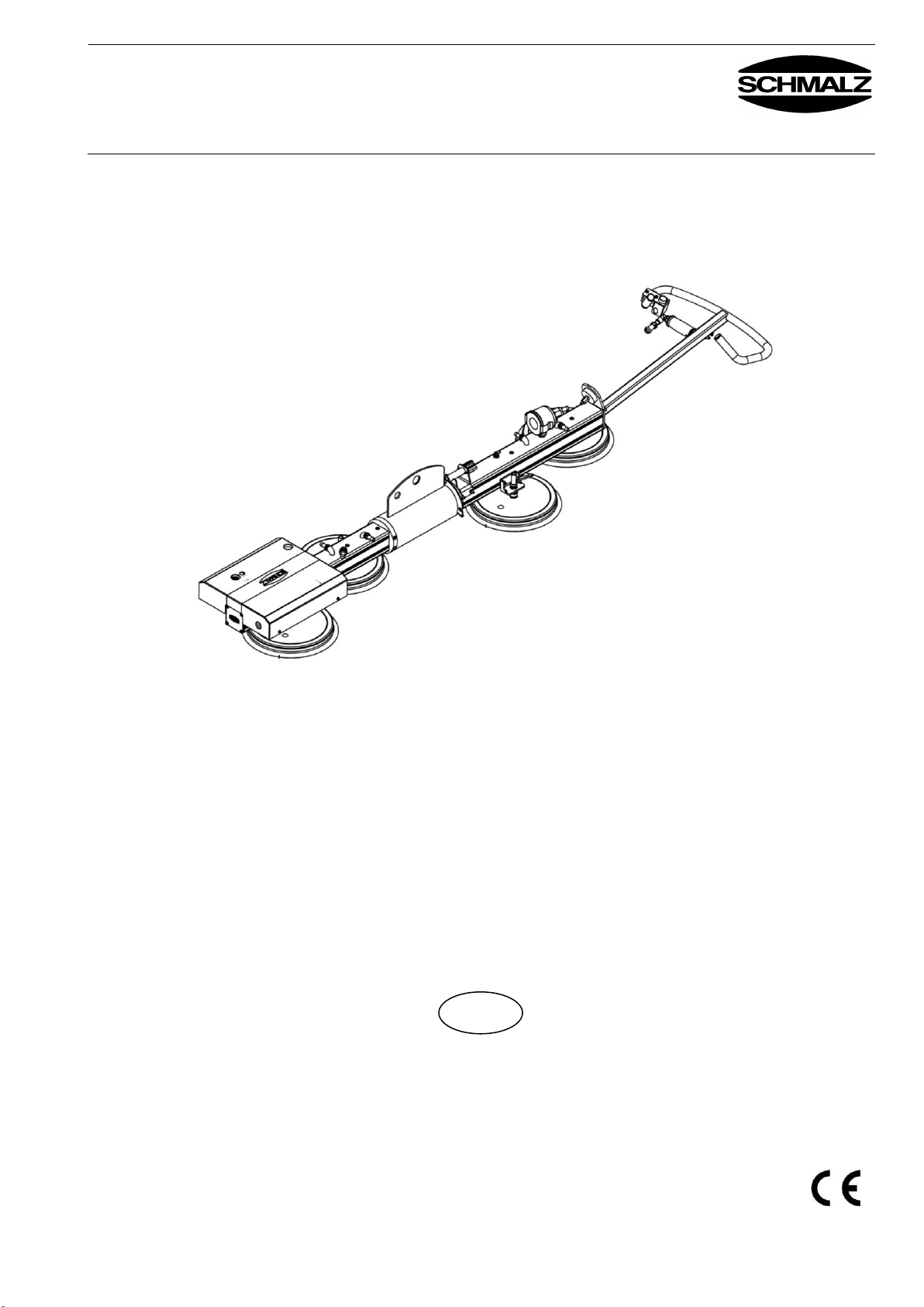
VACUMASTER HHVM
J. Schmalz GmbH
Aacher Straße 29
D - 72293 Glatten
Tel +49 (0) 7443/ 2403 - 0
Fax +49 (0) 7443 / 2403 - 259
http://www.schmalz.com
e-mail: schmalz@schmalz.de
30.30.01.00218 / Index 00 Last updated 03/2013 Page 5/22
The lifting device with pneumatic vacuum generation is used for lifting flat items,
workpieces, or plates from a range of materials at low heights, as well as porous
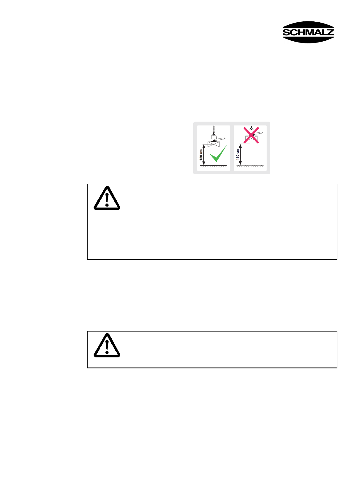
workpieces such as particle boards or MDF sheets. This means that the center
of gravity of the workpiece must not be lifted above 1.80 m. In addition to
purely horizontal or vertical handling, workpieces can also either be picked
up horizontally and swiveled vertically or picked up vertically and swiveled
horizontally. Workpiece swiveling is limited to +90° or -90°.
The lifting device may only be used while hung from a suspension
bar/bolt.
No people or animals may be transported with the load or the lifting
device.
For safety reasons, the lifting device may not be modified or changed
without approval.
The operating, maintenance and servicing conditions prescribed in
these operating instructions must be observed.
The maximum permissible load must not be exceeded.
The continuous sound pressure output by the device is less than 70 db(A).
As the load is held to the suction plates of the device by means of a vacuum,
it is dropped as soon as the vacuum collapses.
This can occur during a vacuum generator failure. In such cases, a built-in
reservoir maintains the vacuum for a short safety period (depends on the
density of the workpiece surface).
In the event of a failure, set down the load immediately if possible.
If this is not possible, leave the danger zone immediately.
The device generates very high suction, which can suck in hair and items
of clothing. Do not look into the suction connection when the device is
switched on. Eyes can be sucked in.
The user’s workplace is at the handle. Users must stand in a way that ensures
that they can see the vacuum gauge at all times.
1.9 Instructions for
users of the lifting
device
If you use the lifting device, ensure that you have been appropriately trained
before you start operations for the first time. You must have read and
understood the operating instructions, in particular the “Safety” section.
Ensure that only authorized personnel work with the device.
You are responsible for third parties in the working area of the device.
Local safety regulations apply. In Germany, this includes, but is not limited to
BGR 500.
Other safety instructions in this manual do not replace these –they are to be
considered as additions.