Nouvag DP 30 User manual

DispenserDP30
Instructions for use
EN

2©NOUVAGAG • 31678 • V20221125 • Allrightsreserved
DISPENSERDP30 INSTRUCTIONS FOR USE
SYMBOLS
General warning sign General
mandatory action
Refer to
instructions for use
Manufacturer Date of manufacture Use-by date
Do not use if the
package is damaged Not for reuse Separate collection
required (WEEE)
Biological hazard Not made with natural
rubber latex
Contains or presence
of Phthalate
Batch code Catalog number Serial number
Medical device EOSTERILE Sterilized using
ethylene oxide
Authorized represen-
tative in the European
Community
Water resistance Equipotentiality Indication of pump
flow direction
Type BF applied part Foot switch
0197
European Conformity
mark
Certified by the TÜV
Rheinland North
America Group
CONGRATULATIONS ON YOUR PURCHASE OF A PRODUCT FROM NOUVAG.
We are pleased that you have chosen a quality product from NOUVAG and thank you very much for the trust you
have placed in us.
These instructions for use will familiarize you with the device and its functions so that you can apply and use
them correctly.

3
©NOUVAGAG • 31678 • V20221125 • Allrightsreserved
INSTRUCTIONS FOR USE DISPENSERDP30
CONTENT
PRODUCT DESCRIPTION 4
Intended use and operation
Target group
Contraindications
Ambient conditions
SAFETY INFORMATION 5
EMC Manufacturer’s Declaration of Conformity
Integrated peristaltic pump
Possible risks and side effects
Modifications and misuse
Essential requirements
During use
SCOPE OF DELIVERY 7
DEVICE OVERVIEW 8
Front view
Rear view
SETUP 9
Connection to the power supply
Potential equalization connection according to DIN42801
Device preparation
Device setup
OPERATION 11
Switching the device on and off
Regulation of the infiltration process
Peristaltic pump
Functional check
CLEANING AND DISINFECTION 12
Control unit and foot switch
Tubing set REF6022a/b
MAINTENANCE 13
Replacing the control unit fuses
Safety inspections
MALFUNCTIONS AND TROUBLESHOOTING 14
ACCESSORIES AND SPARE PARTS 15
Information on disposal
TECHNICAL DATA 15
WARRANTY COVERAGE 16
Post market surveillance
Service points
APPENDIX 17

4©NOUVAGAG • 31678 • V20221125 • Allrightsreserved
DISPENSERDP30 INSTRUCTIONS FOR USE
PRODUCT DESCRIPTION
INTENDED USE AND OPERATION
The DispenserDP30 serves as Infiltration pump into the connective tissue and is used in the following field of
applications:
¬Tumescent infiltration for liposuction (Liposuction)
¬Infiltration pump for venous treatment, varicose veins (Angiology)
The DispenserDP30 may only be operated by trained and qualified personnel in professional settings.
TARGET GROUP
Adult patients, in good health status.
CONTRAINDICATIONS
Infectious wounds Liposuction may only be performed after the treatment of the infection and necrotic tissue.
In principle, generally poor health of the patient.
Liposuction shortly after a strict diet of the patient.
Morbid obesity (obesity) Large suction volumes increase the risk of death due to fluid shifts.
Intravascular infusion of liquids.
Relevant cases in the literature must be considered.
AMBIENT CONDITIONS
TRANSPORT AND STORAGE DURING USE
Relative humidity max. 90 % max. 80 %
Temperature 0 – 60 °C 10 – 30 °C
Atmospheric pressure 700 – 1’060 hPa 800 – 1’060 hPa

5
©NOUVAGAG • 31678 • V20221125 • Allrightsreserved
INSTRUCTIONS FOR USE DISPENSERDP30
SAFETY INFORMATION
It is essential to bear the following information in mind:
Every use of the DispenserDP30 different to the product description defined in section I -
> causes risks for patients and trained personnel. If physical examinations and therapies are carried out
without use of the devices then the device must be removed from the place of treatment.
EMC MANUFACTURER’S DECLARATION OF CONFORMITY
The use of (RF) Radio Frequency emitting devices and equipment as well as the occurrence of negative environ-
mental factors in the close area of the DispenserDP30 may cause unexpected or adverse operation. The connec-
tion or the placing of other devices in close vicinity is not allowed.
Use only accessories and cables as specified in the product description. Further observe the EMC manufacturer
declaration of conformity.
INTEGRATED PERISTALTIC PUMP
The integrated peristaltic pump is used for infiltration of watery solutions into the human connective tissue. The
infiltration pump is not designed for intravascular infusion of liquids.
POSSIBLE RISKS AND SIDE EFFECTS
¬Improper use can result in tissue or organ injuries to the patient or cuts to the user or a third person.
¬In rare cases, a treatment can lead to mild neurological disorders. In very rare cases, a treatment can lead to
endovenous heat-induced thrombosis.
6©NOUVAGAG • 31678 • V20221125 • Allrightsreserved
DISPENSERDP30 INSTRUCTIONS FOR USE
MODIFICATIONS AND MISUSE
Modifications/manipulations on the DispenserDP30 and its accessories are not permitted. Failure to follow
these instructions can have unpredictable consequences for the user, the patient or third parties. For conse-
quential complications, resulting from illicit modifications/manipulations the manufacturer assumes no
responsibility and the guarantee is void.
NOUVAG recommends the use of Klein tumescent anesthesia solution. The use of other solutions is on the
responsibility of the surgeon. When infiltrating tumescent anesthesia solution, do not exceed 0.05% w/w anes-
thetic concentration.
ESSENTIAL REQUIREMENTS
Do not use the device if the shipping box has holes/cracks on the flat surfaces, and/or if the Styrofoam protec-
tive packaging is broken.
The DispenserDP30 may only be operated by qualified and trained personnel!
The use of third-party products is the responsibility of the operator. Functionality and patient safety cannot
be guaranteed with third-party accessories.
Repairs may only be performed by authorized NOUVAG service technicians!
Improper use or repair of the device, or failure to observe these instructions, relieves NOUVAG from any obli-
gation arising from warranty provisions or other claims.
Prior to using the device, before startup, and before operation, the user must always ensure that the device
and accessories are in good working order and are clean, sterile and operational.
Ensure that the operating voltage setting corresponds to the local mains voltage.
The DispenserDP30 may only be operated under constant supervision of medical personnel. The absence
of a warning buzz to indicate malfunctions of the device requires the permanent control of the volumetric
displacement of the pump.
DURING USE
The device is not sterile on delivery. Please observe the instructions C >.
At choice of the instrument the user has to make sure it confirms to ENISO10993, means that it’s biocompatible.
Do not use device in the vicinity of flammable mixtures!
The use of the DispenserDP30 other than that for which it was designed (see I -
>) is not permitted. The responsibility is solely carried by the operator.
SAFETY INFORMATION

7
©NOUVAGAG • 31678 • V20221125 • Allrightsreserved
INSTRUCTIONS FOR USE DISPENSERDP30
SCOPE OF DELIVERY
REF DESCRIPTION QUANTITY
4180 DispenserDP30 control unit 1
1770 Stand for irrigation fluid bottle 1
31678 DispenserDP30 Instructions for use 1
SELECTIVELY: SET NO. 4186 – DISPENSERDP30 CONTROL UNIT WITH ON/OFF FOOT SWITCH
REF DESCRIPTION QUANTITY
1513nou ON/OFF foot switch 1
SELECTIVELY: SET NO. 4187 – DISPENSERDP30 CONTROL UNIT WITH VARIO FOOT SWITCH
REF DESCRIPTION QUANTITY
1501nou VARIO foot switch 1

8©NOUVAGAG • 31678 • V20221125 • Allrightsreserved
1
2
3 4
5
6
7
8
9
10
11 12 13 14 15 16
DISPENSERDP30 INSTRUCTIONS FOR USE
1 Indicator light for Power ON/OFF 2 Operating panel with pump displacement scale 3 Control dial to set pump displacement
volume 4 Release key for tubing set bracket 5 Swiveling arm with integrated tubing set holder 6 Tubing set 7 Stand for irrigation
fluid bottle 8 Roller clam 9 Venting valve 10 Irrigation fluid container 11 Type plate with type designation, reference number,
serial number, information on power supply and device fuse 12 Foot switch socket (device rear) 13 Potential equalization 14 Power
entry module with power plug socket 15 Power entry module with power switch 16 Power entry module with national voltage
setting
DEVICE OVERVIEW
FRONT VIEW
REAR VIEW

9
©NOUVAGAG • 31678 • V20221125 • Allrightsreserved
INSTRUCTIONS FOR USE DISPENSERDP30
CONNECTION TO THE POWER SUPPLY
In order to prevent the risk of electric shock, the device may only be connected to a power network with a PE
protective earth conductor.
If the voltage shown does not correspond to the local mains voltage, the grey fuse holder must be set to the cor-
rect voltage:
SETUP
1 Switch off device.
2 Unplug the power cable.
3 Use a screwdriver to open the fuse slot.
4 Remove the fuse holder.
5 Remove the grey fuse holder and reinsert it so that the local mains voltage setting is shown in the small win-
dow.
6 Slide the grey fuse holder back in and close the fuse slot.
7 Check the mains voltage shown on the fuse slot.
8 Plug the power cable back into the device.
POTENTIAL EQUALIZATION CONNECTION ACCORDING TO DIN42801
At the back of the device a potential equalization plug is installed, according to DIN42801.
The additional potential equalization has the task of equalizing potentials between different parts of conductive
materials that can be touched at the same time, or reducing potential differences.
This connection must be used, to protect the patient, the user and third parties from touch voltages.
The equipotential plug is marked with the following symbol:
DEVICE PREPARATION
1 Insert the stand for the irrigation fluid into the stand holder.
2 Plug the foot switch plug into the foot switch socket at the rear of the control unit.
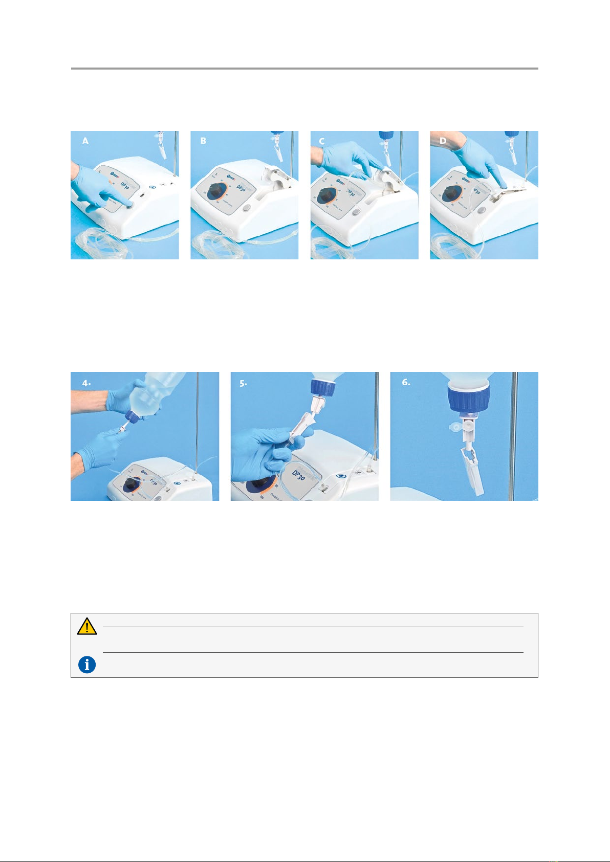
3 Assemble the tubing set (see images).
Check the expiry date of the tubing set and ensure that the packaging is not damaged. Using non-sterile
tubing sets can result in serious infection, and in extreme cases, can be fatal.
Use only the NOUVAG tubing set REF6022a/b, otherwise the function cannot be guaranteed.
When inserting the tubing set, notice the arrow marked on the tubing set bracket. It indicates the direction
of flow of the infiltration liquid.
10 ©NOUVAGAG • 31678 • V20221125 • Allrightsreserved
DISPENSERDP30 INSTRUCTIONS FOR USE
A Press the release key for tubing set bracket to open the pump.
B The compartment with the integrated tubing bracket opens.
C Place the tubing set into the tubing bracket provided in such a way that the end of the tubing set with
the spike exits the pump to the rear of the control unit. Check that the tubing is secure.
D With the tubing set inserted, press the compartment downwards until it clicks into place.
4 Insert the spike at the end of the tubing set into the infiltration fluid bottle and hang the bottle onto the
stand.
5 Open the roller clamp on the tubing set as far as it will go.
6 Open the vent valve at the spike.
7 Connect the control unit to the power socket.
Ensure that the operating voltage setting corresponds to the local mains voltage!
The container of infiltration fluid may weigh a maximum of 2 kg. Heavier containers can cause the device to
tip over.
The infiltration fluid flow is regulated via the pump integrated in DispenserDP30. Therefore, always leave
the roller clamp open to the maximum.
DEVICE SETUP
¬Place the DispenserDP30 and all required accessories and instruments on an even, non-slip surface and make
sure you have good access to all controls.
¬Do not allow the operating range of the device (including the cable) to be compromised by limiting factors.
¬The system operation panel and the infiltration liquid bottle must be fully visible at all times.
¬It must be explicitly ensured that no objects can fall onto the foot switch.
¬The power plug at the rear of the device must be accessible at all times.
SETUP

11
©NOUVAGAG • 31678 • V20221125 • Allrightsreserved
INSTRUCTIONS FOR USE DISPENSERDP30
OPERATION
SWITCHING THE DEVICE ON AND OFF
The main switch “I/O” on the back of the unit is used to switch the control unit on and off. Switching off can be
done at any time and is not dependent on a switch-off procedure.
The green LED light at the top left of the control panel lights up when the main switch has been activated and
the unit is ready for operation.
REGULATION OF THE INFILTRATION PROCESS
Control dial in conjunction with ON/OFF foot switch The desired volumetric displacement is set with the
control dial. The pumping process is started by actuating the ON/OFF foot switch. The volumetric displace-
ment can be varied at any time using the control dial.
Control dial in conjunction with VARIO foot switch The maximum volumetric displacement can be varied
at any time using the control dial, even while the foot switch is being pressed. Control using the VARIO foot
switch regulates the volumetric displacement of the pump up to the set maximum value.
PERISTALTIC PUMP
Turn control dial clockwise from the OFF position. Pump starts, liquid emerges from the open tube end. Turning
the dial up to the maximum value controls the increase in volumetric displacement.
The pump stops immediately when the release button of the pump compartment is pressed.
FUNCTIONAL CHECK
Prior to DispenserDP30 startup or use of accessory equipment, the user must always ensure that each individual
component is in good working order, free of defects, clean, sterile and operational. The tube set has to correspond
with the correct flow direction and the pump has to function. The green LED is on after the device is switched on.
To check if the device is in working order, press the foot switch as far as it will go and slowly turn the control dial
on the device through the entire performance range. The maximum flow rate of 210 ml/min. must be reached at
the top end of the scale at the control dial.
In the event of problems, please check that the roller clamp on the tubing set is open as far as it will go and that
the silicon section on the tubing set has been correctly inserted in the tubing bracket.
With ON/OFF foot switch With VARIO foot switch

12 ©NOUVAGAG • 31678 • V20221125 • Allrightsreserved
DISPENSERDP30 INSTRUCTIONS FOR USE
CLEANING AND DISINFECTION
Clean and disinfect the devices after every treatment!
CONTROL UNIT AND FOOT SWITCH
Wipe the outside using tested surface disinfectant or 70 % of isopropyl alcohol. The front plate of the control unit
is sealed and can be wiped clean.
TUBING SET REF6022A/B
Single-use tubing sets may not be reused!
Used tubing sets must be disposed of properly.
Don’t use tube set when pack is already opened or damaged!
Do not use tubing set if expired.
Use only NOUVAG tubing sets with REF6022a/b.
Sterility cannot be guaranteed by reusing and re-sterilization of tubing sets. The characteristics of the device
may change resulting in serious infections or, in worst case, the death of the patient.

13
©NOUVAGAG • 31678 • V20221125 • Allrightsreserved
1 2 3 4 5
INSTRUCTIONS FOR USE DISPENSERDP30
MAINTENANCE
REPLACING THE CONTROL UNIT FUSES
Users can replace faulty control unit fuses themselves. These are located at the rear of the device in the fuse slot
beside the power switch:
1 Switch off device.
2 Unplug the power plug.
3 Open the fuse slot using a screwdriver.
4 Replace the faulty fuse T 1A, 250 V AC.
5 Slide the fuse holder back in and close the fuse slot.
6 Check the mains voltage shown on the fuse slot.
7 Plug in the power plug again.
SAFETY INSPECTIONS
The essential requirements have been defined and assessed within the risk analysis. The results of the analysis
are stored in the risk management file of the manufacturer.
The performance of safety inspections on medical devices is required by law in several countries. The safety
inspection is a regular safety check that is compulsory for those operating medical devices. The objective is to
ensure that device defects and risks to patients, users or third parties are identified in time.
The STI (Safety Technical Inspection) for the DispenserDP30 shall be executed every 2years by authorized
experts. Results shall be documented.
The service manual, wiring diagrams, and descriptions are available upon request from the manufacturer.
NOUVAG offers a safety inspection service for its customers. Addresses can be found in the appendix of this
instructions for use under S > . For further information please contact our technical service
department.
1 Fuse slot locking mechanism 2 Display window for voltage setting 3 Fuse slot 4 Fuse 1 5 Fuse 2

14 ©NOUVAGAG • 31678 • V20221125 • Allrightsreserved
DISPENSERDP30 INSTRUCTIONS FOR USE
MALFUNCTIONS AND TROUBLESHOOTING
MALFUNCTION CAUSE SOLUTION REFER TO INSTRUCTIONS FOR USE
Device is
not functional
(Indicator
light is off)
Control unit not switched
on
Set the power switch « I/O»
to « I »
S >
Power connection not
established
Connect the control unit to
the mains power supply
C >
Incorrect operating
voltage
Check the mains voltage C >
Faulty fuse Replace fuse R >
Pump
doesn’t work
(Indicator
light is on)
Infiltration quantity set
too low or set to « OFF»
Raise pump performance by
turning control switch up
R >
Tubing set incorrectly
inserted
Insert tubing set correctly D >
Incorrect operation Check instructions for use D >
Foot switch was not
pressed
Press foot switch down,
if infiltration process is
controlled via the foot switch
R >
Roller clamp is closed Open roller clamp all the
way
D >
Foot switch
doesn’t work
(Indicator
light is on)
Foot switch is not
connected
Connect foot switch with the
socket on rear of device
D >
D >
Incorrect operation Check instructions for use D >
R >
If the problem cannot be solved please contact your supplier or an authorized service center. Addresses can be found in the appendix of this instruc-
tions for use under S > .

15
©NOUVAGAG • 31678 • V20221125 • Allrightsreserved
INSTRUCTIONS FOR USE DISPENSERDP30
ACCESSORIES AND SPARE PARTS
ACCESSORIES
DESCRIPTION REF
ON/OFF foot switch 1513nou
VARIO foot switch 1501nou
Stand for irrigation fluid bottle 1770
Disposable tubing set with spike and Luer-Lock connection, sterile, 4 m 6022a/b
To order any additional parts, please contact our customer service department.
INFORMATION ON DISPOSAL
When disposing of the device, device components and accessories, the regulations issued by the legislator must
be followed.
To ensure environmental protection, old devices can be returned to the dealer or manufacturer.
Contaminated single-use tubing sets are subject to specific disposal requirements. Please observe prevailing
national disposal regulations.
When discarding the device components and accessories, please comply with the issued statutory regula-
tions. With regard to the preservation of the environment old equipment may be returned to the distributor
or manufacturer.
TECHNICAL DATA
Voltage, switchable 100 V~ / 115 V~ / 230 V~, 50 / 60 Hz
Fuse power supply 2 fuses, T 1
A, 250
V
AC
Power consumption 40 VA
Volumetric displacement 0 – 12,5 l/h
Maximum pressure with closed tube set 2,0 bar
Applied part Type BF*
Protection class Class I
Dimensions (W x D x H) 260 x 250 x 110
mm
Net weight control unit 2,4 kg
Maximum weight at the stand for the irrigation fluid bottle 2,0 kg
The mentioned volumetric displacement is only valid for aqueous solutions without any instrument connected.
* Applied part is the tube set with its attached instruments.

16 ©NOUVAGAG • 31678 • V20221125 • Allrightsreserved
DISPENSERDP30 INSTRUCTIONS FOR USE
WARRANTY COVERAGE
NOUVAG warrants this product to be free from defects in workmanship and materials for a period of
twelve(12)months from the original date of purchase. If the warranty card is returned for registration or the
warranty extension is requested on our website within 4weeks from the date of purchase, the warranty coverage
is extended for a period of 6months, wear parts are excluded from the warranty. During this warranty period,
NOUVAG agrees to either repair or replace the product at its option if the product fails to function properly under
normal use and service and such failure is due solely to a defect in workmanship or materials.
This warranty is void if repair or service of the product is performed or attempted by anyone not authorized by
NOUVAG to do so, or if a replacement part not authorized by NOUVAG is used in any repair or service.
POST MARKET SURVEILLANCE
In the event of incidents related to the use of the medical device, please contact immediately the manufac-
To provide adequate information, please compile the incident questionnaire at the web address
Nouvag.com > Contact us > Incident questionnaire.
SERVICE POINTS
Switzerland
NOUVAGAG
St. Gallerstrasse 25
9403 Goldach
Phone +41 71 846 66 00
www.nouvag.com
Germany
NOUVAGGmbH
Schulthaissstrasse 15
78462 Konstanz
Phone +49 7531 1290- 0
info-[email protected]om
www.nouvag.com
A complete list of NOUVAG certified service points are found on the NOUVAG website: Nouvag.com > Service
0197

17
©NOUVAGAG • 31678 • V20221125 • Allrightsreserved
Electromagnetic compatibility (EMC)
Remark:
The Product subsequently referred to herein always denotes the Dispenser DP 30.
Changes or modifications to this product not expressly approved by the manufacturer may result in increased emissions or decreased immunity
performance of the product and could cause EMC issues with this or other equipment. This product is designed and tested to comply with
applicable regulations regarding EMC and shall be installed and put into service according to the EMC information stated as follows.
WARNING
Use of portable phones or other radio frequency (RF) emitting equipment, including accessories (antennas e.g.) in distances below
30 cm (12 inches) to the product, may cause unexpected or adverse operation.
WARNING
The product is suitable for use in hospitals other than in the vicinity of active devices of the HF surgical devices or except in HF
screening rooms used for magnetic resonance imaging.
WARNING
The product shall not be used adjacent to, or stacked with, other equipment. If adjacent or stacked use is necessary, the product
shall be tested to verify normal operation in the configuration in which it is being used.
Essential Performance
The essential performance is that the infiltration of tumescent solution in the fat tissue taking into account the infiltration flow rate and pressure is
maintained. The maximum infiltration flow rate deviation is ± 25%, the infiltration flowrate is between 60 and 230ml/min and the maximum pressure
is 2.5bar.
Compliant Cables and Accessories
WARNING
The use of accessories, transducers and cables other than those specified may result in increased emissions or decreased immunity
performance of the product.
The table below lists cables, transducers, and other applicable accessories for which the manufacturer claims EMC compliance.
NOTE: Any supplied accessories that do not affect EMC compliance are not listed.
Description Length max.
Power supply cord REF 22261 / 22262 / 22264 / 22266 3.0m
Foot pedal IPX8 REF 1501nou / 1513nou 2.9m
Guidance and manufacturer’s declaration
–
electroma
g
netic emissions
The Product is intended for use in the electromagnetic environment specified below. The customer or the user of the Product should
assure that it is used in such an environment.
Emissions test Compliance Electromagnetic environment - guidance
RF emissions
CISPR 11
Group 1 The Product uses RF energy only for its internal function.
Therefore, its RF emissions are very low and are not likely to
cause any interference in nearby electronic equipment.
RF emissions
CISPR 11
Class B The Product is suitable for use in all establishments, including
domestic establishments and those directly connected to the
public low-voltage power supply network that supplies buildings
used for domestic purposes.
Harmonic emissions
IEC 61000-3-2
Class A
Voltage fluctuations/flicker emissions
IEC 61000-3-3
complies
Guidance and manufacturer’s declaration
–
electromagnetic immunity
The Product is intended for use in the electromagnetic environment specified below. The customer or the user of the Product should
assure that it is used in such an environment.
Immunity tests IEC 60601
Test level
Compliance level Electromagnetic environment - guidance
Electrostatic discharge
(ESD)
IEC 61000-4-2
+/- 8 kV contact
+/- 2 kV, +/- 4 kV, +/- 8 kV,
+/- 15 kV air
+/- 8 kV contact
+/- 2 kV, +/- 4 kV, +/- 8 kV,
+/- 15 kV air
Floors should be wood, concrete or ceramic
tile. If floors are covered with synthetic
material, the relative humidity should be at
least 30 %.
Electrical fast
transient/burst
IEC 61000-4-4
+/- 2 kV with 100kHz
for power supply lines
+/- 1 kV with 100kHz
for input/output lines
+/- 2 kV with 100kHz
for power supply lines
+/- 1 kV with 100kHz
for input/output lines
Mains power quality should be that of a typical
commercial or hospital environment.
Surge
IEC 61000-4-5
+/- 0.5 kV, +/- 1 kV
differential mode
+/- 0.5 kV, +/- 1 kV, +/- 2 kV
common mode
+/- 0.5 kV, +/- 1 kV
differential mode
+/- 0.5 kV, +/- 1 kV, +/- 2 kV
common mode
Mains power quality should be that of a typical
commercial or hospital environment.
Voltage dips, short
interruptions and voltage
variations on power
supply input lines
IEC 61000-4-11
0 % UT; for 0,5 cycle
with 0, 45, 90, 135, 180, 225,
270, 315 degree
0 % UT; for 1 cycle
0 % UT; for 0,5 cycle
with 0, 45, 90, 135, 180, 225,
270, 315 degree
0 % UT; for 1 cycle
Mains power quality should bet hat of a typical
commercial or hospital environment.
If the user of the Product requires continued
operation during power mains interruptions, it
is recommended that the Product be powered
INSTRUCTIONS FOR USE DISPENSERDP30
APPENDIX

18 ©NOUVAGAG • 31678 • V20221125 • Allrightsreserved
Electromagnetic compatibility (EMC)
Remark:
The Product subsequently referred to herein always denotes the Dispenser DP 30.
Changes or modifications to this product not expressly approved by the manufacturer may result in increased emissions or decreased immunity
performance of the product and could cause EMC issues with this or other equipment. This product is designed and tested to comply with
applicable regulations regarding EMC and shall be installed and put into service according to the EMC information stated as follows.
WARNING
Use of portable phones or other radio frequency (RF) emitting equipment, including accessories (antennas e.g.) in distances below
30 cm (12 inches) to the product, may cause unexpected or adverse operation.
WARNING
The product is suitable for use in hospitals other than in the vicinity of active devices of the HF surgical devices or except in HF
screening rooms used for magnetic resonance imaging.
WARNING
The product shall not be used adjacent to, or stacked with, other equipment. If adjacent or stacked use is necessary, the product
shall be tested to verify normal operation in the configuration in which it is being used.
Essential Performance
The essential performance is that the infiltration of tumescent solution in the fat tissue taking into account the infiltration flow rate and pressure is
maintained. The maximum infiltration flow rate deviation is ± 25%, the infiltration flowrate is between 60 and 230ml/min and the maximum pressure
is 2.5bar.
Compliant Cables and Accessories
WARNING
The use of accessories, transducers and cables other than those specified may result in increased emissions or decreased immunity
performance of the product.
The table below lists cables, transducers, and other applicable accessories for which the manufacturer claims EMC compliance.
NOTE: Any supplied accessories that do not affect EMC compliance are not listed.
Description Length max.
Power supply cord REF 22261 / 22262 / 22264 / 22266 3.0m
Foot pedal IPX8 REF 1501nou / 1513nou 2.9m
Guidance and manufacturer’s declaration
–
electroma
g
netic emissions
The Product is intended for use in the electromagnetic environment specified below. The customer or the user of the Product should
assure that it is used in such an environment.
Emissions test Compliance Electromagnetic environment - guidance
RF emissions
CISPR 11
Group 1 The Product uses RF energy only for its internal function.
Therefore, its RF emissions are very low and are not likely to
cause any interference in nearby electronic equipment.
RF emissions
CISPR 11
Class B The Product is suitable for use in all establishments, including
domestic establishments and those directly connected to the
public low-voltage power supply network that supplies buildings
used for domestic purposes.
Harmonic emissions
IEC 61000-3-2
Class A
Voltage fluctuations/flicker emissions
IEC 61000-3-3
complies
Guidance and manufacturer’s declaration
–
electromagnetic immunity
The Product is intended for use in the electromagnetic environment specified below. The customer or the user of the Product should
assure that it is used in such an environment.
Immunity tests IEC 60601
Test level
Compliance level Electromagnetic environment - guidance
Electrostatic discharge
(ESD)
IEC 61000-4-2
+/- 8 kV contact
+/- 2 kV, +/- 4 kV, +/- 8 kV,
+/- 15 kV air
+/- 8 kV contact
+/- 2 kV, +/- 4 kV, +/- 8 kV,
+/- 15 kV air
Floors should be wood, concrete or ceramic
tile. If floors are covered with synthetic
material, the relative humidity should be at
least 30 %.
Electrical fast
transient/burst
IEC 61000-4-4
+/- 2 kV with 100kHz
for power supply lines
+/- 1 kV with 100kHz
for input/output lines
+/- 2 kV with 100kHz
for power supply lines
+/- 1 kV with 100kHz
for input/output lines
Mains power quality should be that of a typical
commercial or hospital environment.
Surge
IEC 61000-4-5
+/- 0.5 kV, +/- 1 kV
differential mode
+/- 0.5 kV, +/- 1 kV, +/- 2 kV
common mode
+/- 0.5 kV, +/- 1 kV
differential mode
+/- 0.5 kV, +/- 1 kV, +/- 2 kV
common mode
Mains power quality should be that of a typical
commercial or hospital environment.
Voltage dips, short
interruptions and voltage
variations on power
supply input lines
IEC 61000-4-11
0 % U
T;
for 0,5 cycle
with 0, 45, 90, 135, 180, 225,
270, 315 degree
0 % UT; for 1 cycle
0 % U
T;
for 0,5 cycle
with 0, 45, 90, 135, 180, 225,
270, 315 degree
0 % UT; for 1 cycle
Mains power quality should bet hat of a typical
commercial or hospital environment.
If the user of the Product requires continued
operation during power mains interruptions, it
is recommended that the Product be powered
70 % U
T
; for 25/30 cycles
0 % UT; for 5 sec
70 % U
T
; for 25/30 cycles
0 % UT; for 5 sec
from an uninterruptible power supply or a
battery.
Power frequency
(50/60Hz) magnetic field
IEC 61000-4-8
30 A/m 30 A/m Power frequency magnetic fields should be at
levels characteristic of a typical location in a
typical commercial or hospital environment.
Note: UT is the a.c. mains voltage prior to application of the test level.
Guidance and manufacturer’s declaration
–
electromagnetic immunity for not life support equipment
The Product is intended for use in the electromagnetic environment specified below. The customer or the user of the Product should
assure that it is used in such an environment.
Immunity tests IEC 60601
Test level
Compliance level Electromagnetic environment - guidance
Portable and mobile RF communications
equipment should be used no closer to any part
of the Product, including cables, than the
recommended separation distance calculated
from the equation applicable to the frequency of
the transmitter.
Recommended separation distance:
Conducted RF
IEC 61000-4-6
3 V rms
0.15 MHz to 80 MHz
6 V rms
inside ISM bands between
150 kHz to 80 MHz
80% AM bei 1 kHz
3 V rms
0.15 MHz to 80 MHz
6 V rms
inside ISM bands between
150 kHz to 80 MHz
80% AM bei 1 kHz
d = 0,35 P
Radiated RF
IEC 61000-4-3
3 V/m
80 MHz to 2.7 GHz
80% AM bei 1 kHz
3 V/m
80 MHz to 2.7 GHz
80% AM bei 1 kHz
d = 0,35 P 80 MHz to 800 MHz
d = 0,7 P 800 MHz to 2,7 GHz
Where P is the maximum output power rating in
the transmitter in watts (W) according to the
transmitter manufacturer and d is the
recommended separation distance in metres
(m).
Field strengths from fixed RF transmitters, as
determined by an electromagnetic site survey a,
should be less than the compliance level in each
frequency range b.
Interference may occur in the vicinity of
equipment marked with the following symbol:
Note 1: At 80 MHz and 800 MHz, the higher frequency range applies.
Note 2: These guidelines may not apply in all situations. Electromagnetic propagation is affected by absorption and reflection from
structures, objects and people.
a Fixed strengths from fixed transmitters, such as base stations for radio (cellular/cordless) telephones and land mobile radios,
amateur radio, AM and FM radio broadcast and TV broadcast cannot be predicted theoretically with accuracy. To access the
electromagnetic environment due to fixed RF transmitters, and electromagnetic site survey should be considered. If the
measured field strength in the location in which the Product is used exceeds the applicable RF compliance level above, the
Product should b observed to verify normal operation. If abnormal performance is observed, additional measures may be
necessary, such as reorienting or relocating the Product.
b over the frequency range 150 kHz to 80 MHz, field strengths should be less than 3 V/m.
DISPENSERDP30 INSTRUCTIONS FOR USE
APPENDIX

19
©NOUVAGAG • 31678 • V20221125 • Allrightsreserved
Electromagnetic immunity against high-frequency wireless communication devices
Test frequenc
y
MHz
Frequency
band
MHz
Communication
service
Modulation Maximum
Performance
W
distance
m
Test level
V/m
385 380 to 390 TETRA 400 Pulse modulation
18 Hz 1.8 0.3 27
450 430 to 470 GMRS 460,
FRS 460
FM
± 5 kHz Hub
1 kHz Sinus
2 0.3 28
710
704 to 787 LTE Band 13, 17 Pulse modulation
217 Hz 0.2 0.3 9
745
780
810
800 to 960
GSM 800/900,
TETRA 800,
iDEN 820,
CDMA 850,
LTE Band 5
Pulse modulation
18 Hz 2 0.3 28
870
930
1720
1700 to 1990
GSM 1800,
CDMA 1900,
GSM 1900,
DECT,
LTE Band 1, 3,
4, 25; UMTS
Pulse modulation
217 Hz 2 0.3 28
1845
1970
2450 2400 to 2570
Bluetooth,
WLAN 802.11
b/g/n,
RFID 2450,
LTE Band 7
Pulse modulation
217 Hz 2 0.3 28
5240
5100 to 5800 WLAN 802.11 a/n Pulse modulation
217 Hz 0.2 0.3 9 5500
8785
Recommended separation distances between
portable and mobile RF communications equipment and the not life support equipment
The Product is intended for use in an electromagnetic environment in which radiated RF disturbances are controlled. The customer or the
user of the Product can help prevent electromagnet interference by maintaining a minimum distance between portable and mobile RF
communications equipment (transmitters) and the Product as recommended below, according to the maximum output power of the
communications equipment.
Rated maximum output power
of transmitter
W
Separation distance according to frequency of transmitter
m
150 kHz to 80 MHz
d = 0,35 P
80 MHz to 800 MHz
d = 0,35 P
800 MHz to 2.5 GHz
d = 0,7 P
0,01 0,04 0,04 0,07
0,1 0,11 0,11 0,22
1 0,35 0,35 0,7
10 1,1 1,1 2,2
100 3,5 3,5 7
For transmitters rated at a maximum output power not listed above, the recommended separation distance d in metres (m) can be
estimated using the equation applicable to the frequency of the transmitter, where P is the maximum output power rating of the transmitter
in watts (W) according to the higher frequency range applies.
Note 1: At 80 MHz and 800 MHz, the separation distance fort the higher frequency range applies.
Note 2: These guidelines may not apply in all situations. Electromagnetic propagation is affected by absorption and reflection from
structures, objects and people.
INSTRUCTIONS FOR USE DISPENSERDP30
APPENDIX

0197
©NOUVAG AG • 31678 • V20221125 • All rights reserved
NOUVAGAG
St. Gallerstrasse 25
9403 Goldach
Switzerland
Phone +41 71 846 66 00
www.nouvag.com
NOUVAGGmbH
Schulthaissstrasse 15
78462 Konstanz
Germany
Phone +49 7531 1290- 0
info-[email protected]om
www.nouvag.com
Table of contents
Popular Dispenser manuals by other brands

Krowne
Krowne MasterTap Sight 'N Sip Infuser Faucet manual

Ecomist
Ecomist EcoProC instructions

Bartscher
Bartscher 500379 manual

Bobrick
Bobrick B-922 Instruction for installation and maintenance

Franke
Franke STRATOS STRX627 Installation and operating instructions

BIOTIC Industries
BIOTIC Industries LAC-TEK STAINLESS manual


Dolphin
Dolphin BCL632FS-2 Installation and maintenance guide

OPHARDT HYGIENE
OPHARDT HYGIENE SanTRAL Plus JRU 1 quick start guide

BIEMMEDUE
BIEMMEDUE HERO Instruction and maintenance manual

WEPA
WEPA satino 331400 Assembly instructions

Commercial Care
Commercial Care CCSA01W user manual

U-Line
U-Line H-70657 quick start guide