Novacor R.TEST Evolution 4 User manual
User Manual - R.Test Evolution 4 EN V2019-12/06/2019 Page 1
R.TEST Evolution 4
User Manual
NOVACOR
4 Passage Saint-Antoine
92500 Rueil-Malmaison
FRANCE
R.TEST Evolution 4 Manual NOVACOR - All rights reserved


User Manual - R.Test Evolution 4 EN V2019-12/06/2019 Page 3
1Contents
1CONTENTS ............................................................................................................................................... 3
2INTRODUCTION........................................................................................................................................5
2.1 DESCRIPTION OF THE DEVICE ......................................................................................................................... 5
2.2 THIS MANUAL ............................................................................................................................................ 5
2.3 SAFETY INFORMATION ................................................................................................................................. 5
2.4 SYMBOLS ................................................................................................................................................ 10
2.5 GUARANTEES........................................................................................................................................... 12
2.5.1 Specific Guarantees of the device.................................................................................................... 12
2.5.2 Specific Guarantees of the accessories............................................................................................ 12
2.5.3 Limits of guarantee ......................................................................................................................... 12
2.5.4 Responsibilities ................................................................................................................................ 12
2.5.5 Users information............................................................................................................................ 12
2.5.6 Copyrights ....................................................................................................................................... 12
3DESCRIPTION OF THE HARDWARE ......................................................................................................... 13
3.1 THE RECORDER R.TEST EVOLUTION 4.......................................................................................................... 14
3.1.1 The Device ....................................................................................................................................... 14
3.1.2 The Buttons ..................................................................................................................................... 14
3.2 R.TEST-PC USB CABLE ............................................................................................................................. 15
3.3 ACCESSORIES ........................................................................................................................................... 15
4OPERATION............................................................................................................................................ 17
4.1 COLLECTION OF ECG SIGNAL....................................................................................................................... 17
4.2 RECORDING MODES .................................................................................................................................. 18
4.2.1 Manual Recording ........................................................................................................................... 18
4.2.2 Automatic Recording (with the option of patient activated recordings)......................................... 18
4.3 OPERATION IN MANUAL RECORDING MODE.................................................................................................... 18
4.4 OPERATION IN AUTOMATIC RECORDING MODE ............................................................................................... 18
4.5 AUTOMATIC SIGNAL ANALYSIS .................................................................................................................... 19
4.5.1 Basal heart rate............................................................................................................................... 19
4.5.2 Storage of the heart rate................................................................................................................. 19
4.5.3 Detection of rhythm disorders......................................................................................................... 20
4.6 CONSECUTIVE EVENTS ............................................................................................................................... 22
4.6.1 Simple Events................................................................................................................................... 22
4.6.2 Superimposed Events ...................................................................................................................... 22
4.6.3 Multiple Events................................................................................................................................ 23
4.7 SETTING OF THE EVENTS IN MEMORY ............................................................................................................ 23
4.8 DEFAULT PROGRAM.................................................................................................................................. 24
5CONNECTING THE PATIENT.................................................................................................................... 25
5.1 ORDER OF CONNECTION............................................................................................................................. 26
5.2 CHOICE OF LEAD ....................................................................................................................................... 26

User Manual - R.Test Evolution 4 EN V2019-12/06/2019 Page 4
5.2.1 Standard Configuration CM5........................................................................................................... 26
5.2.2 “Neck-Sternum” Configuration........................................................................................................ 26
5.3 INSERTING NEW BATTERIES ......................................................................................................................... 26
5.4 PROGRAMMING OF THE RECORDER .............................................................................................................. 27
5.5 CONNECTING THE PATIENT CABLE TO THE R.TEST ........................................................................................... 28
5.6 PLACING THE ELECTRODES AND CONNECTING THE R.TEST ................................................................................. 28
5.6.1 Preparation...................................................................................................................................... 28
5.6.2 “Neck-Sternum” configuration with solid gel electrodes ................................................................ 28
5.6.3 Configuration in CM5: pre-gelled electrodes................................................................................... 30
5.7 START UP AND HOOK-UP TEST ..................................................................................................................... 31
5.7.1 Start-up in continuous mode ........................................................................................................... 31
5.7.2 Disconnection Test .......................................................................................................................... 31
5.8 REMOVING THE R.TEST.............................................................................................................................. 31
5.8.1 End of monitoring............................................................................................................................ 31
5.8.2 Temporary Interruption of the monitoring...................................................................................... 31
5.8.3 To Unplug the cable from R.Test ..................................................................................................... 32
5.9 CONNECTION TO A COMPUTER .................................................................................................................... 32
5.9.1 Connecting the R.Test PC cable ....................................................................................................... 32
5.9.2 Disconnection of the cable .............................................................................................................. 33
5.10 RESUMING MONITORING............................................................................................................................ 33
5.10.1 Without changing batteries ........................................................................................................ 33
5.10.2 Changing batteries...................................................................................................................... 33
6MAINTENANCE ...................................................................................................................................... 35
6.1 HANDLING AND USE .................................................................................................................................. 35
6.2 CLEANING ............................................................................................................................................... 35
6.3 AFTER-SALES SERVICE................................................................................................................................ 36
6.4 STORAGE AND DISPATCHING ....................................................................................................................... 36
6.5 PREVENTIVE MAINTENANCE ....................................................................................................................... 36
7SPECIFICATIONS..................................................................................................................................... 37
8ACCESSORIES AND CONSUMABLES ........................................................................................................ 39

User Manual - R.Test Evolution 4 EN V2019-12/06/2019 Page 5
2Introduction
2.1 Description of the device
The R.Test Evolution 4 is a miniature automatic ECG arrhythmia detection device; it is
quick and easy to fit to the patient. It is designed to detect and store the most
important pathologic events (symptomatic or asymptomatic) as well as the patient’s
continuous heart rate, and is capable of up to 32 days of ambulatory monitoring.
The system consists of a unit weighing approximately 40 grams that can be worn by
the patient unobtrusively and without any discomfort. The R.Test Evolution 4 is
connected to the patient by a system of electrodes and a neck cable. Events stored
by the R.Test Evolution 4 are then transferred to a computer for interpretation via a
USB cable.
The use of a computer will allow:
- the programming of the conditions and criteria for each recording made by the
R.Test Evolution 4.
- in addition, to select, organize and store the results of the examinations, then to
print a customised report according to your needs.
2.2 This manual
This manual describes the physical operation, instructions, characteristics, technical
specifications and the particular recommendations of use of the R.Test Evolution 4
and its accessories.
Although the greatest care was taken in its drafting, in order to make it as complete
as possible, NOVACOR does not accept any responsibility for any errors, omissions or
inaccuracies which it may contain.
The functionalities of the device and the accessories, as well as the contents of the
manual, can be modified by NOVACOR without notice.
2.3 Safety information
Intended Users:
The R.Test Evolution 4 is intended for use by a licensed physician, or a person
working under their supervision, after having read the R.Test 4 and RTSoft Ultima
user manuals. No further training is necessary to use the equipment.
The patient is required to wear the device and should trigger recordings manually,
the physician should ensure that the mental and physical condition of the patient is
compatible with an R.Test procedure. The physician should inform the patient of the

User Manual - R.Test Evolution 4 EN V2019-12/06/2019 Page 6
nature of the test and any actions that are required (e.g. removal of the recorder for
a shower, manual activation of recordings etc.).
The ECG strips recorded by the R.Test 4 during the procedure are then analysed to
determine the presence (not the absence) of a pathological arrhythmia.
The R.Test 4 should not be used on patients with potentially life-threatening
arrhythmias who require inpatient monitoring or on patients who the attending
physician thinks should be hospitalised.
R. Test 4 is intended for use in an electromagnetic environment in which disturbances due to RF
radiation are controlled.
Electromagnetic compatibility
This medical device complies with the applicable electromagnetic compatibility standards and will
ensure that any electromagnetic interference, from radio frequency transmitters or other electronic
devices, does not create an additional hazard.
The user of the medical device can help to avoid electromagnetic interference by maintaining a
minimum distance, depending on the maximum power of the radio frequency transmission
equipment.
Warning: RF portable communication devices (including peripherals such as antenna cables and
external antennas) should not be used closer than 30 cm (12 inches) to any part of R.Test 4, including
the cables specified by the manufacturer. Otherwise, the performance of these devices may be
impaired.
Warning: The R.Test 4 should not be used next to other devices, or stacked with them, because this
may cause a malfunction. If this is necessary, this unit and other devices should be observed for
normal operation.
Warning: The use of accessories other than those specified or sold by NOVACOR as replacement
parts may result in increased emission or decreased immunity of the medical device and may cause
improper operation.
Recommendations and manufacturer's declaration
The R.Test 4 is intended for use in an electromagnetic environment as specified below. The
clinician and the user should ensure that the device is used in such an environment
Electromagnetic emissions
Emissions tests
Conformity
Electromagnetic environment - remarks
Impact of Electromagnetic
field emitted by the device
(Radiated emissions)
(CISPR 11)
Group 1
R.Test 4 uses RF energy for its internal function.
Therefore, its radiofrequency emissions are very
low and are not likely to create any interference with
nearby equipment.
User Manual - R.Test Evolution 4 EN V2019-12/06/2019 Page 7
Emissions from the power
terminals
(Emissions conducted)
(CISPR 11)
Class B
R.TEST4 is suitable for use in all settings, including
home health care environment and the environment
of a professional health care facility.
Harmonic current emission
(IEC61000-3-2)
Not applicable
Voltage variations, voltage
fluctuations and flicker
(IEC61000-3-3)
Not applicable
Electromagnetic immunity
The R.Test.4 is intended for use in an electromagnetic environment as specified below. The clinician and
the user should ensure that the R.Test 4 is used in such an environment
Immunity test
Test level according
to IEC60601
Test level according to
IEC60601
Electromagnetic
environment / remarks
Electrostatic
discharge (ESD)
(IEC61000-4-2)
8 kV in contact
± 15 kV to the air
8 kV in contact
± 15 kV to the air
Home health care
environment and an
environment of a
professional health care
facility.
Fast electrical
transients in
bursts
(IEC61000-4-4)
± 2 kV for power lines
Not applicable (no relation
to the public electricity
grid)
Home health care
environment and an
environment of a
professional health care
facility.
Shocks
(IEC61000-4-5)
± 1 kV in Differential
mode
± 2 kV in common
mode
Not applicable (no relation
to the public electricity
grid)
Home health care
environment and an
environment of a
professional health care
facility.
Magnetic field at
assigned
industrial
frequency
(IEC61000-4-8)
30 A/m
30 A/m
Home health care
environment and an
environment of a
professional health care
facility.
User Manual - R.Test Evolution 4 EN V2019-12/06/2019 Page 8
Electromagnetic immunity
The R.Test.4 is intended for use in an electromagnetic environment as specified below. The clinician and
the user should ensure that the R.Test 4 is used in such an environment
Immunity test
Test level according
to IEC60601
Test level according to
IEC60601
Electromagnetic
environment / remarks
Voltage dips,
brief
interruptions
and voltage
variations
(IEC61000-4-
11)
0% UT for 0.5 cycles
At 0 °, 45 °, 90 °, 135
°, 180 °, 225 °, 270 °
and 315 °
0% UT for 1 cycle
70% UT for 25 cycles
at 50 Hz
For 30 cycles at 60 Hz
Single phase: at 0 °
Not applicable (no relation
to the public electricity
grid)
Home health care
environment and an
environment of a
professional health care
facility.
Voltage
interruptions
(IEC61000-4-
11)
0% UT;
for 250 cycles at 50 Hz
for 300 cycles at 60 Hz
Not applicable (no relation
to the public electricity
grid)
Home health care
environment and an
environment of a
professional health care
facility.
Electromagnetic Immunity, Portable Radio Frequency Equipment
Immunity test
Test level
according to
IEC60601
Test level
according to
IEC60601
Electromagnetic environment / remarks
WARNING: RF portable communication devices (including peripherals such as antenna cables
and external antennas) should not be used closer than 30 cm (12 inches) to any part of the
R.Test.4, including the cables specified by the manufacturer. Otherwise, the performance of these
devices may be impaired.
Electrostatic
discharge (ESD)
(IEC61000-4-2)
3 V/m
80 MHz at 2.7
GHz
80 % MA at 1
kHz
10 V/m
80 MHz at 2.7
GHz
80 % MA at 1
kHz
3 V/m
80 MHz at 2.7
GHz
80 % MA at 1
kHz
10 V/m
80 MHz at 2.7
GHz
80 % MA at 1
kHz
Home health care environment
Professional health care institution
User Manual - R.Test Evolution 4 EN V2019-12/06/2019 Page 9
Proximity fields
issued by RF
wireless
communication
devices
(IEC 61000-4-3
interim method)
9 V/m
710 MHz, 745
MHz,
780 MHZ,
5240 MHz,
5550 MHz,
5785 MHz
27 V/m
385 MHz
28 V/m
450 MHz, 810
MHz,
870 MHz, 930
MHz,
1720 MHz,
1845 MHz,
1970 MHz,
2450 MHz
9 V/m
710 MHz, 745
MHz,
780 MHZ,
5240 MHz,
5550 MHz,
5785 MHz
27 V/m
385 MHz
28 V/m
450 MHz, 810
MHz,
870 MHz, 930
MHz,
1720 MHz,
1845 MHz,
1970 MHz,
2450 MHz
Home health care environment and an
environment of a professional health care
facility.
Conducted
disturbances,
induced by RF
fields
(IEC610004-6)
3V 150KHz to
80MHz
6V in ISM
band and
band between
0.15 MHZ and
80 MHZ,
amateur radio
band included
80% MA at 1
KHz
3V 150KHz to
80MHz
6V in ISM
band and
band between
0.15 MHZ and
80 MHZ,
amateur radio
band included
80% MA at 1
KHz
Home health care environment and an
environment of a professional health care
facility.
The electromagnetic field strengths of fixed radio frequency transmitters, as determined by an
electromagnetic environment measurement (a), shall be less than the compliance level for each
frequency range. Interference may occur near equipment identified by the following symbol:
Note: These specifications may not apply in all situations. Electromagnetic propagation is affected by
the absorption and reflection of structures, objects and people.
(a) The intensities of the electromagnetic fields of fixed radio frequency transmitters, such as base
stations for mobile (cellular / wireless) telephones, mobile radios, radio amateurs, AM / FM radio
transmissions and TV transmissions cannot be accurately determined theoretically. To evaluate the
electromagnetic environment due to fixed radio frequency transmitters, an electromagnetic
environment measurement must be performed. If the measured RF field strength in the immediate
environment of use of the product exceeds the radio frequency compliance level (specified above), it
is necessary to test the product performance to verify that it conforms to the specifications. If
User Manual - R.Test Evolution 4 EN V2019-12/06/2019 Page 10
abnormal performance is noted, additional measures may be necessary, such as reorienting or
moving the R.Test 4.
Precautions for use must be taken with regard to electromagnetic compatibility (EMC) phenomena.
The R.Test 4 must be installed and put into service in accordance with the EMC recommendations
above.
Malfunctions can be caused by the proximity of portable or mobile RF communications equipment.
R.Test 4 is not protected from the effects of the discharges of an external
defibrillator.
The minimal amplitude of the physiological patient signals is 0.5 mV. The use of
the equipment close to this minimal level can generate incorrect results.
The equipment or system is under the responsibility of qualified staff. This
equipment or system can be the source of radio interferences or be the source of
abnormal operations of another apparatus located in the immediate vicinity.
Some care over positioning could be necessary.
The equipment should not be used adjacent to, or placed upon other equipment.
If this use is necessary, a check for good performance of the equipment in this
configuration must be made.
2.4 Symbols
This sign on an apparatus indicates to the user that additional information,
available in the accompanying documents, that must be consulted.
IP24
R.Test 4 works exclusively with an internal power source and complies with
standards of protection for units in class BF.
Fitted with its ECG cable, R.Test 4 is classified IP24 (protected against water)
R.TEST 4 is not an apparatus of category AP nor APG
R.TEST 4 is designed for continuous service.
CEM
R.TEST 4 is in conformity with the Electromagnetic standard of Compatibility EN
60 601-1-2. However, if it is used in a very specific way, there can be some
problems with interference
User Manual - R.Test Evolution 4 EN V2019-12/06/2019 Page 11
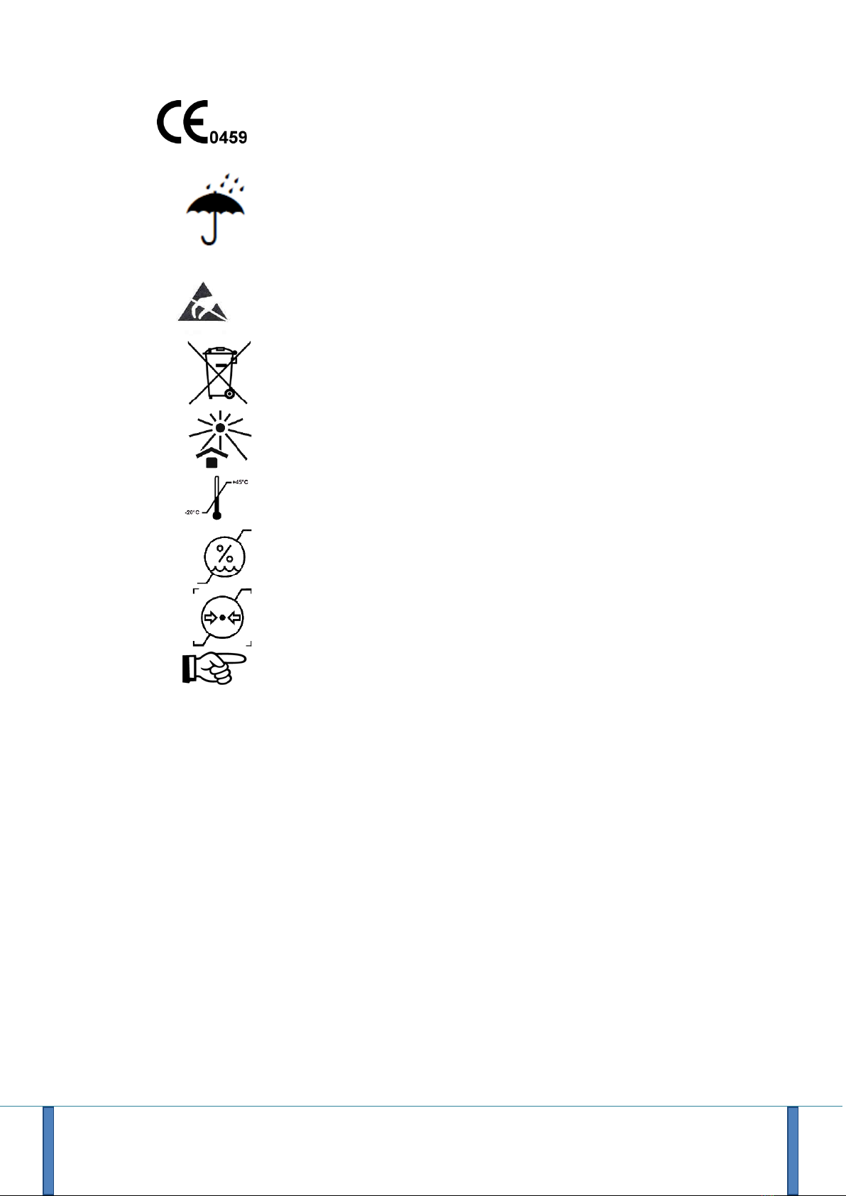
CE Mark, according to European Directive 93/42/CEE for medical devices
The device does not possess any specific protection against moisture, as a
consequence, it is recommended to store it in a dry place.
Risk associated with the ESDs
The product must be disposed of through a suitable system to allow recovery and
recycling
Store away from light
Storage Temperature Limits
Humidity Storage Limits
Pressure Storage Limits
Connecting the ECG cable to the patient:
When connecting it:
Always connect the cable to the recorder first, then to the electrodes on the
patient.
When removing the unit:
Always disconnect the ECG cable from the electrodes on the patient before
unplugging the cable from the recorder.
NOVACOR will provide electrical circuit diagrams and information about the nature of the materials
for customers if required.

User Manual - R.Test Evolution 4 EN V2019-12/06/2019 Page 12
2.5 Guarantees
NOVACOR undertakes to deliver merchandise conforming to the technical
specifications mentioned and to replace any merchandise recognised as being
defective during the period of guarantee.
2.5.1 Specific Guarantees of the device
NOVACOR guarantees the unit for the period of one year from the date of delivery
against any defect resulting in the unit functioning abnormally.
2.5.2 Specific Guarantees of the accessories
The parts or components not considered an integral part of the device, and in
particular the accessories and cables, do not benefit from any particular guarantee.
2.5.3 Limits of guarantee
The guarantee does not apply:
1. if the device is repaired or opened outside of our workshops.
2. if the device is damaged following negligence, accident, or use that does not
conform with the procedures described in the instruction manual.
If necessary, please contact your local distributor or our after-sales service directly.
We do not accept any return of goods without prior arrangement.
2.5.4 Responsibilities
NOVACOR will not, under any circumstances, be held responsible for physical or
material damage of whatever nature, resulting either directly or indirectly from
improper use of the unit or from failure to follow the instructions in the user manual.
Although NOVACOR manufactures products to the highest standards, justifying
customer confidence, it cannot guarantee or be responsible for the validity or
accuracy of the measurements made with its units. Therefore, connection of the unit
to the patient, interpretation of the ensuing clinical results and the diagnosis
established from them are entirely the responsibility of the physician. No damage,
either direct or indirect, resulting from the use of one of its units can be attributed to
NOVACOR, excluding the repair of the unit within the limits of the guarantee.
2.5.5 Users information
All the customers duly recorded at NOVACOR or if necessary, by its distributors, will
be kept informed as well as possible of various developments of R.TEST Evolution 4.
2.5.6 Copyrights
R.Test Evolution 4 –User Manual EN ©2019 Novacor SAS - All rights reserved.
R.Test is a registered trademark of NOVACOR SAS.
Windows is a registered trademark of Microsoft Corporation.

User Manual - R.Test Evolution 4 EN V2019-12/06/2019 Page 13
3Description of the hardware
R.TEST Evolution 4 is a recorder / analyser of ECG
events
➢ambulatory,
➢automatic or manual,
➢single channel,
➢long term,
Intended for asymptomatic and/or symptomatic
patients.
User Manual - R.Test Evolution 4 EN V2019-12/06/2019 Page 14
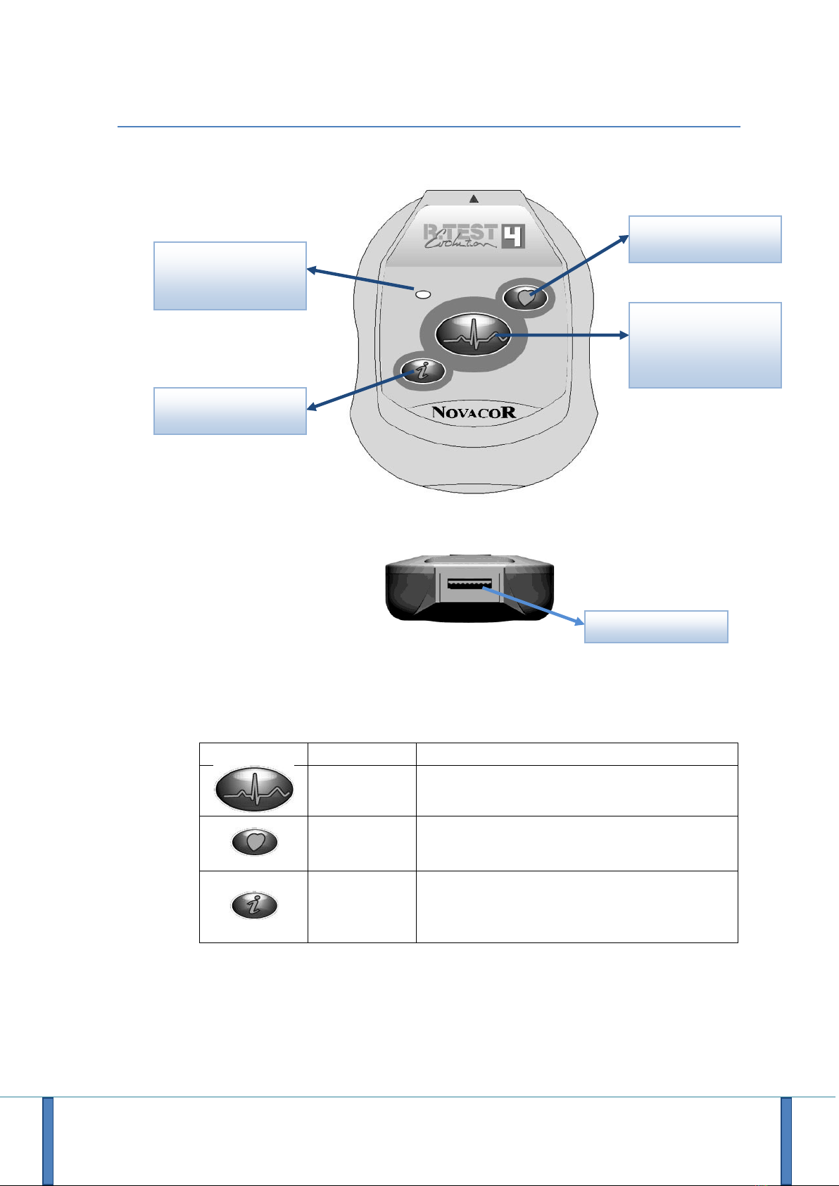
3.1 The recorder R.TEST Evolution 4
3.1.1 The Device
3.1.2 The Buttons
Button
Programmable
Description
No
Start button, to start a procedure
Patient activation button
Yes
Activation of the modulated acoustic transmission of
the real-time ECG signal
A second press, starts the QRS beeps
Yes
Indication of the memory state:
- If red LED: memory full for one of the programmed
events
- If green led: no memory category is filled
Initialisation
&
Manual Event Recording
Real time transmission
Multifunction LED
Indicator
Information
ECG/USB Connector
User Manual - R.Test Evolution 4 EN V2019-12/06/2019 Page 15
3.2 R.Test-PC USB Cable
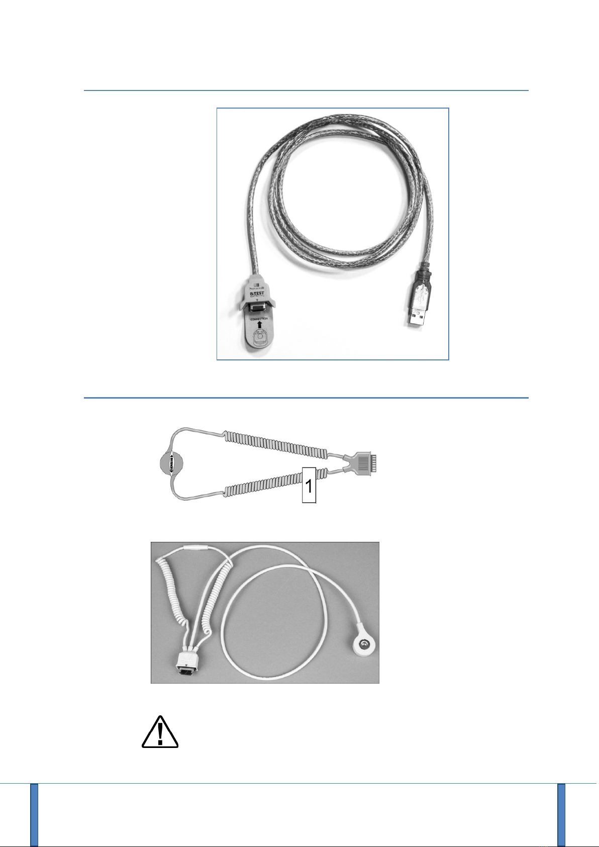
3.3 Accessories
Neck cable
(Connection Necklace)
CM5 Cable
(standard 40 cm or long
60 cm)
The use of accessories, sensors and cables other than those specified can induce
an increase in the levels of electromagnetic emission or a reduction in the levels
of immunity of the equipment.


User Manual - R.Test Evolution 4 EN V2019-12/06/2019 Page 17
4Operation
4.1 Collection of ECG signal
The surface ECG signal is collected according to a bipolar configuration between two
ECG electrodes especially adapted to the R.Test. The apparatus is integrated directly
with one of the electrodes, in contact with the patient’s sternum. The second
electrode, placed either behind the neck or on the patient’s side, is connected to the
R.Test by using the supplied accessory.
The physician is free to choose between the “neck-sternum” and the “CM5 lead”
configurations, there is a specially designed cable for each.
The neck-sternum configuration allows the collection of the ECG signal characterised
by:
•a morphology and an amplitude of QRS similar to V2,
•significantly different right and left ventricular activations,
•generally optimal P waves amplitude.
The CM5 configuration allows collection of the ECG signal characterised by:
•a morphology and an amplitude of QRS similar to V5,
•an amplitude often greater than the ‘neck-sternum’ configuration
The CM5 cable may provide a better recording of ST changes and give more flexibility
when the anatomy of the patient’s sternum makes it impossible to connect the
R.Test normally.
The R.Test stores significant ECG events in its memory.
The physician can pre-program the duration of these events and the mode in which
they will be recorded:
- automatically (for asymptomatic problems), according to recognition criteria
specific to each pathology,
- or by patient activation (pressing the recording key) (for symptomatic events,
whether they be cardiac or not).

User Manual - R.Test Evolution 4 EN V2019-12/06/2019 Page 18
4.2 Recording modes
The clinician may decide to use one, or both, of the two options below, depending on
the software options available:
4.2.1 Manual Recording
The ECG is recorded by the R.Test, for one predetermined length of time, without
analysis or processing, when the patient presses on the manual event button on the
device.
Each recording is obtained according to the pre and post event durations set in the
current program, configurable by the clinician, via the software.
4.2.2 Automatic Recording (with the option of patient activated recordings)
The ECG signal is processed and analysed in real time, and the most significant
pathologies are stored into the memory of the device.
Each recording is obtained according to the criteria and to the pre and post event
durations set in the current program, configurable by the clinician, via the software.
4.3 Operation in manual recording mode
This mode is intended for symptomatic patients, for whom one wishes to carry out a
recording of an event or symptom, even if this symptom is not very frequent.
The patient simply has to press the R.Test recording key and the ECG recording will
then be saved in the unit’s memory. This recording is stored, without being analysed
or interpreted, so that the physician can examine it later.
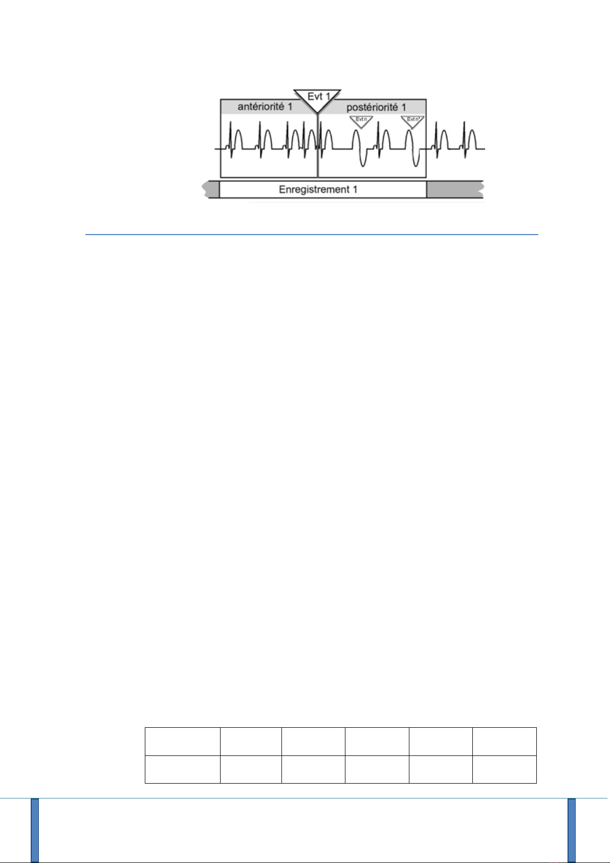
4.4 Operation in automatic recording mode
The R.Test monitors the ECG signal continuously and stores it in a loop memory,
which therefore contains, at any given moment, the previous few minutes of ECG;
this means that a given duration of the ECG preceding a detected event can be
included in the recording. This duration, called the pre-event, can vary from 5
seconds to 5 minutes.
During the detection of an event, R.TEST Evolution 4 will store the ECG corresponding
to the pre-event recording time defined for this type of event and will continue to
memorise the ECG until the end of the post-event recording time defined for this
type of event.
If during post-event, other events are detected, they will be simply marked on the
ECG but the R.Test will not start a new recording (see also § 4.6.3 Multiple Events).
User Manual - R.Test Evolution 4 EN V2019-12/06/2019 Page 19
4.5 Automatic Signal Analysis
The analysis of the ECG takes place in real time in the R.Test: as the ECG signal is
stored in the buffer, the R.Test’s microchip, using a specific software algorithm,
carries out the following operations automatically:
•identification of the QRS and possible elimination of artefacts,
•determination of the morphology of the QRS,
•calculation of R-R intervals and the basal heart rate,
•continuous storage of the heart rate,
•recognition and hourly counting of arrhythmic events,
•memorisation of selected episodes with date and time, QRS and events
characteristics
4.5.1 Basal heart rate
The reference R-R interval, which corresponds to the basal heart rate, is obtained by
continuous calculation of the average of the preceding few R-R intervals recognised
by the R.Test as being “normal”. Excluded from this average are R-R intervals
considered not “normal”, these include: periods of artefact, pauses, intervals
preceding and following premature QRS (in order to also eliminate compensatory
pauses).
By default this calculation is carried out on the last 8 “normal” R-R intervals collected
(noted RR8N).
4.5.2 Storage of the heart rate
At regular intervals, the R.Test stores 3 values, enabling assessment of the patient’s
heart rate trend to be made: minimum rate, mean rate and maximum rate. The
duration of this interval is chosen according to the length of time that the patient is
connected to the unit.
The R.Test therefore also provides the physician with continuous monitoring of the
minimum, mean and maximum heart rates for a period of up to 32 days.
Duration of
examination
< 48h
From 2 to
4 days
From 4 to
8 days
From 8 to
16 days
From 16 to
32 days
Sampling of
the HR
1'
2'
4'
8'
16'

User Manual - R.Test Evolution 4 EN V2019-12/06/2019 Page 20
4.5.3 Detection of rhythm disorders
Arrhythmias detected by the R.Test are classified in several categories. Some
automatic functions of the R.Test Evolution 4 may be available only as additional
options.
4.5.3.1 Fast Rhythm disorders (premature QRS and salvos)
A QRS is considered as premature if the R-R interval preceding it is lower by a given
percentage (standard program 25%) compared to the base period (RR8N).
The R.Test characterises premature QRS according to:
- The morphology:
Normal or Narrow QRS as “Supraventricular”
Aberrant or Wide QRS as “Ventricular”
- Their organisation:
Isolated QRS, Couplets and Triplets (1, 2 or 3 consecutive premature QRS)
Runs (4 or more consecutive premature QRS).
This identification enables the R.Test to distinguish 8 subcategories of rapid events:
•Isolated Supraventricular Ectopic
•Supraventricular Couplets
•Supraventricular Triplets
•Supraventricular Runs
•Isolated Ventricular Ectopic
•Ventricular Couplets
•Ventricular Triplets
•Ventricular Runs
In the case of the isolated events, couplets and triplets of the same type, the
reserved memory capacity is common. If the memory is full, a new event will replace
another according to the following criteria of gravity: a triplet is more serious than a
couplet, which itself is more serious than an isolated premature QRS.
Standard program: RR < RR8N - 25% * RR8N
4.5.3.2 Absolute Pauses
Characterised by an R-R interval exceeding a certain duration.
Standard program: RR > 2.0 seconds
4.5.3.3 Relative Pauses
Characterised by an R-R interval exceeding a given percentage of the mean reference
R-R interval, providing that it does not follow a premature QRS complex, and that its
duration is shorter than the absolute pause threshold.
Standard program: RR > 175% * RR8N
Table of contents
Other Novacor Medical Equipment manuals

Popular Medical Equipment manuals by other brands


Getinge
Getinge Arjohuntleigh Nimbus 3 Professional Instructions for use

Mettler Electronics
Mettler Electronics Sonicator 730 Maintenance manual

Pressalit Care
Pressalit Care R1100 Mounting instruction

Denas MS
Denas MS DENAS-T operating manual

bort medical
bort medical ActiveColor quick guide

AccuVein
AccuVein AV400 user manual


