Novalynx Nema 110-WS-25N User manual

NovaLynx Corporation
PO Box 240
Grass Valley, CA 95945
Tel: (530) 823-7185 ax: (530) 823-8997
www.novalynx.com
Date: March 1, 2017 to October 1, 2017
Quote Number: 1703WQ002
Subject:
Quotation for WS-25 NEMA J-Box Weat er Station
with options
Model No. Description
110-WS-25N Modular Weat er Station Includes ......
110-WS-25DL-N Data Logger wit Display in NEMA-4X Enclosure
with surge protection, 12 v ,7AH Battery, 100~240vac Charger, 500mb SD memory card
and SD card Reader, Tower Mounting brackets, 6' RS-232 Serial Output cable
200-WS-02 Wind Speed & Direction Sensor w/40' cable
110-WS-25THA Temperature & Humidity Sensor w/40' & Radiation Shield
110-WS-25BP Barometric Pressure Sensor mounted inside J-Box
110-WS-25RG Rain Gauge 8" dia w/60' cable & Tower Mounting Arm
110-WS-25TM Tripod 5 ft & 5 ft Sensor Mast for Sensors & J-Box
( 8.5 ft Height )
Total ...................... $2,335.00
~ ~ ~ SYSTEM OPTIONS ~ ~ ~
110-WS-25SRD Solar Radiation Sensor , w/ 40' & Mounting Arm....................... $ 215.00
110-WS-25SP Solar Panel Battery Charger 10 watt with regulator& Mounts.....$ 405.00 ....
10-WS-25STR Graphical Display Software for Realtime PC Display ...............$ 295.00
Additional Sensors ( Solar Radiation, Evaporation, Soil Temp and or Upgrade sensors are available....
This should allow you to plan for your upcoming purchase. If there is anything else with which we can
assist you with , please do not hesitate to contact Novalynx
Prepared by: Terms and Conditions:
NOVALYNX CORPORATION
Payment.............
Net 30 days OAC • Visa • MasterCard •.
Delivery ..........................15-30 days
ARO
.O.B. point . . . . . . . . . . . . . . . . . . . . . Auburn, California
Warranty ..............................One year
Prices valid . . . . . . . . . . . . . . . . . . . . . . . . . until 1/1/2016
Sales NovaLynx ederal ID# . . . . . . . . . . . . . . . . . 68-0237829

QUICK START
for t e
110-WS-25N Nema Weat er Station
1. Set up t e Tripod and Mount t e Sensor, Wind, Rain,
RH / Temp, ( BP
is connected in the J-Box )
Attach Logger J-Box
to the Vertical Mast of the tripod.
( secure tripod as needed )
Align the Wind Direction Sensor to North.
2. Route the Sensor cables into the J.Box and connect to the
Terminal Board See Hook-Up Drawing for
Actual connections
3. Connect the Red ( + ) Lead Wire
to the +12V Battery Terminal
O
OO
O
This acts as the ON / OFF switch to the logger.
4. The system will operate for around 10 Days on a Fully C arged Battery
To Charge the Battery...Plug the Battery Charger into the 2 pin inline connector, ->>
then plug the Charger into an AC Power Outlet (100~240vac) or an Outdoor rated Ext.Cord
Note : The logger will be ON and Operating during charging,
or
Connect the Optional Solar Panel Charger into the 2 pin plug and Align for max Sun exposure
5. The Logger Display should come up Wind C annels <- select ->
To View all the current sensor reading , do the following steps below
Press the center Select Button and you will See AN0 Wind Speed
1.7 MPH / 34.1 max
( this is the current Speed & the max for the logging period )
Press the up
>
>>
>
Button 3 Times to scroll to the Wind Direction screen
{ Range 0 to 360
/
Wind Direction } 227
/
( SW ) shown
Press the up
>
>>
>
Button again 2 times and you will see
“ Analog Channels” < - SELECT ->
Press the center Select Button and you will See A0 Input Voltage 13.55 vdc
( Reading between should be between 12 to 14 VDC )
Pressing the up
>
>>
>
Button to scroll thru and view channels A0 thru A7
A0 is Input voltage
(battery)
* A4 is Temperature
/
or C
/
, ( Typical Values Shown ) ->>>
* A5 is Humidity %
A6 is Barometric Pressure in.hg. or mb or mm
Ignore the other Channels that are not being used A1, A2 A3,A7
At the end after A7 then “ Analog Channels” < - SELECT -> will be displayed
Press up
>
>>
>
Button to See “Counter Channels” <- select ->
Press the center Select Button and you will See 0: ANEMO 0
Press the up
>
>>
>
Button 2 Times to scroll to the Rain screen
you will See 2: RAIN TODAY 0.00 IN today

The WS-25N is Normally Set-UP Prior to S ipping with the ollowing Settings
A. Date & Time of the shipping Location. ( if Known )
B . 1 minute logging interval.
C . Unused channels are Not Logged., but any optional sensors are added in and programed
D. Default Units Speed is in MPH, Temp in in
/
, Pressure is in Inches of hg., Rain ~Inches
oreign orders units are typically set for Speed ~ m/s, Temp. ~
/
C , Pressure ~mb, rain ~ mm
Standard Sensors are : 200-WS-02 , 110- WS-25THA, 110-WS-25RG, 110-WS-25BP
Check and Verify the Date and Time , Press the up
>
>>
>
Button until the Date And Time Screen Shows
Refer to t e Main Manual to Set or C ange to Your Correct Time, Date and Logging Interval.
Insert t e SD Memory Card into the memory card slot to start recording
To insert the SD™) card, place the card face up into the slot on the front panel and press the card inwards until
the card clicks into place....... To remove card, press the card slightly inward and the card will release
You are Now Connected to the WS-25 and Logging Data to Memory Card.
A New ile .csv will be created at the End of Each Day, ( yyyy, mm, dd ) ( 20160915.csv ) Sept.15, 2016
To View t e Stored Data Remove the Memory Card and Insert it into The USB Memory Card Reader
( The Card Reader needs to be plugged into A USB Port on Your PC )
Data is stored in a text file in Comma Separated Vertical (CSV) format.
Data Record Format Information on Memory Card
There are No Description eaders generated on the stored Data 23 ields are generated , but only the ones being
used are saved, the,,,,, is where the missing fields would appear if the were needed
Sample Data with the 6 Standard Sensors connected WS-25DL 1 min logging, English units
Header Description and the order that they appear for the Standard values
Date and Time, Speed , Gust , Spd count,,,,, Rain , W.Dir., inVolts , Temp /
//
/ F, Hum %, BP in g, cksum
2016-09-15 02:19:00, 0.3, 0.9, 19,,,,,,,,, 0.00, 351, 12.14,,,, 83.1, 26.7, 28.473,, 230
2016-09-15 02:20:00,0.7,1.2,28,,,,,,,,,0.00,351,12.14,,,,83.1,26.7,28.465,,95
2016-09-15 02:21:00,0.9,1.4,31,,,,,,,,,0.00,351,12.14,,,,83.1,26.7,28.465,,8
Sample on same above data imported into a Spreadsheet
The 9 pin Serial RS-232 cable can be connected to the logger for real time serial Output to a PC or Radio if needed.
The The AC Battery Charger is located under the panel and has a viewing hole on the panel for charging Status
“ AC C arger Lig t” Red , means Charging / Green means finished and in Maintain mode ( trickle charging )
Note: The System as been sent up for Your Sensors and Units ..DO Not Select “Restore Defaults”
Refer to the Data Logger Manual or More Detailed advanced information. Rev. March - 2017

W
I
N
D
&
R
A
I
N
T
E
M
P
/
RH
/
B P
Aux
Sensor
Wiring Hook-
up Drawing
110-WS-25N
After connecting
t e wires
Pull on each wire
to make sure
it is connected
securely
Table of contents
Other Novalynx Weather Station manuals
Popular Weather Station manuals by other brands

La Crosse Technology
La Crosse Technology WS-7394U instruction manual
La Crosse Technology
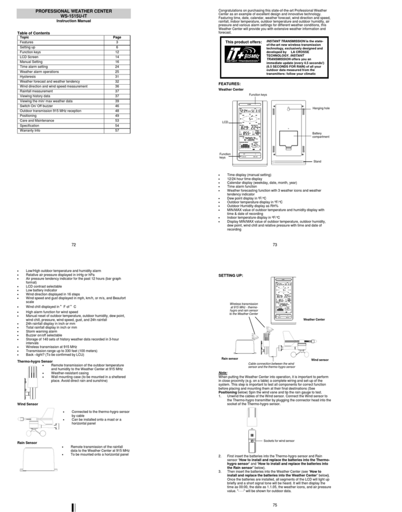
La Crosse Technology WS-1515U-IT instruction manual

La Crosse Technology
La Crosse Technology Wireless Weather Station instruction manual
elv
elv WS 250US Edition operating instructions
YTORA
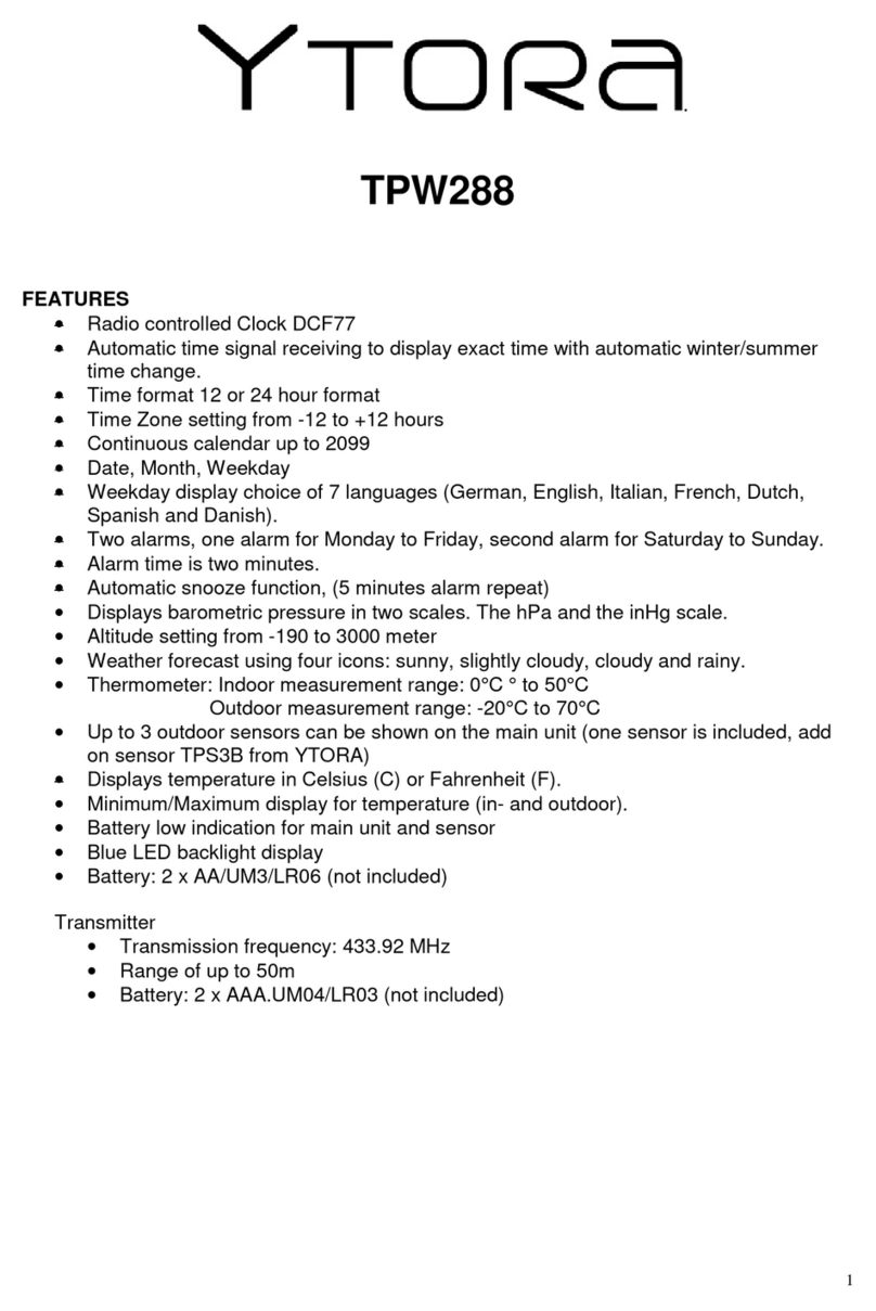
YTORA TPW288 manual
Levenhuk
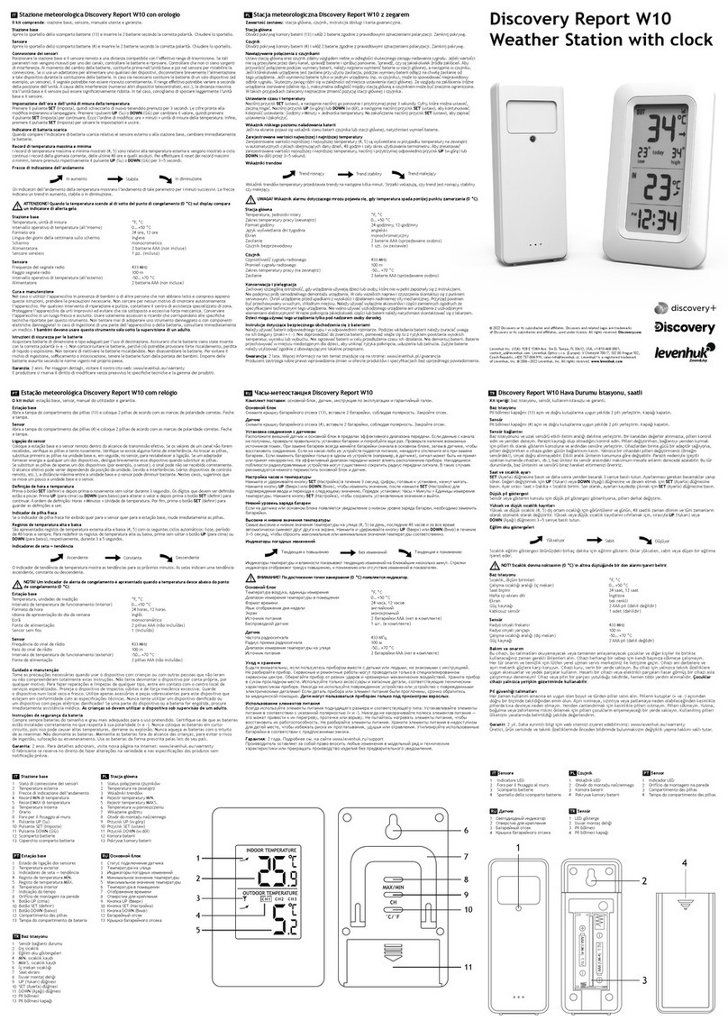
Levenhuk Discovery Report W10 manual


