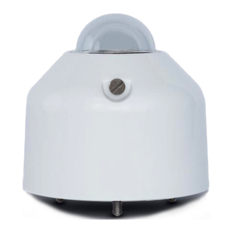
Novasina PascalMaxx +/-50Z User manual

- 1 -
Operating instructions
Differential pressure measurement
instrument for climatic control systems
PascalMaxx
+/-50Z / 500Z / 2‘000Z

Table of contents
1.Product description.................................................................................
2.Scope of delivery....................................................................................
3. Safety .....................................................................................................
4. Installation ..............................................................................................
5. Startup....................................................................................................
6. Configuration possibilities.......................................................................
7.System status signals............................................................................
8.Maintenance & support...........................................................................
9.Device versions ......................................................................................
10. Accessories ..........................................................................................
11.Technical data .......................................................................................
12.Spare parts ..........................................................................................
13.Factory settings ....................................................................................

1. Product description
The Novasina PascalMaxx transmitters are robust
precision measuring instruments for the use in
climate control systems (HVAC). They measure per-
manently the differential pressure, display the values
on a big LCDisplay, provide an accurate analogue
output or a relay contact signal.
The PascalMaxx is available in 3 versions, with
measurement range -50..+50 / 0...500/ 2’000 Pa
with auto zero calibration.
Special features :
• Big LC-Display
• Easy and intuitive menu (3 buttons on front
keypad)
• 1 analogue output (U / I) freely scalable
• 1 integrated relay switch (230V)
• Adjustment capabilities at 2 points (offset and
gain)
offset is adjusted automatically by a valve
• Password protection for all settings
• Keylock
• Various selectable display measurement units
• Permanent online monitoring of all functions
2. Scope of delivery
The PascalMaxx delivery contains:
• Differential pressure measuring instrument
• Strain relief plate including screw set and
4 pcs distance holder
• Operating manual
• Mounting instructions
Check the completeness of the delivery. Incom-
plete deliveries will be replaced by your Novasina
distributor.
3. Safety
• The instruments leave the factory in a faultless
condition. No inappropriate manipulations or
modications are allowed. Please consider all
notices and warning signs on the instrument and
in this operating manual.
• The PascalMaxx instrument has been developed
only for the measurement in fresh air environ-
ments within the dened specications. Use and
run the instrument only for this purpose. In case
of other utilisation beyond the intended use, the
supplier declines all eventually caused damages.
All risks are assumed by the user.
• The installation work shall be only done by skilled
personnel (electrician or similar).
• The PascalMaxx instrument may only be ope-
rated under the specied operating conditions
mentioned in this manual.
• Anywhere faults may occur and cause damages
to material and people, additional safety precau-
tions have to be implemented. In case of any
faults, the dened operating conditions have to
be assured (e.g. limit switch etc.).
• The PascalMaxx instrument is not adequate for
the installation in rooms with explosion hazard.
• The professional installation has to be effected
by observance of the local electrical installation
regulations as well as this operating manual.
• The PascalMaxx contains ESD-sensitive parts.
Please follow the indicated safety measures.
• Use only original Novasina accessories and
spare parts.
• Without any written approval by Novasina no ad-
aptations and modications shall be undertaken
on the PascalMaxx.
4. Installation
1. Read carefully this operating manual prior to start
with the installation of the PascalMaxx.
2. Check the performance data on the label xed
on the instrument and make sure that they cor-
respond with your application. Is the instrument
suitable for your application?
3. Choose the adequate mounting place according
to the application and specications.
4. Respect unconditionally the device specications
and the maximum permissible concentration of
chemical burden in working environments.
5. Avoid to expose the instrument and the sensing
element to a corrosive environment.

Mounting :
1. Remove the bottom of the instrument. If needed
up to 4 holes can be broken through for the
mounting to a wall using screws.
2. In case of unevenness of a wall, please use
the delivered 4 distance holders for screwing the
housing to the wall.
3. Pull the cables through the housing bottom. Prior
to this operation break through the membrane.
Use a needle for punching small holes in the
membrane.
4. For a strain relief use the delivered strain relief
plate.
5. After drilling the holes in the wall and xing the
dowels, the housing bottom can be screwed to
the wall.
6. Screw the cables to the core connectors. Follow
the diagram of the electrician and the connection
diagram of the instrument.
7. Check the wiring carefully before you plug the
connectors to the PCB integrated in the housing
cover.
8. Lead the cover to the upper fastener and click the
cover laterally on the bottom housing part. Check
that the cover is well xed on the bottom part.
9. After switching on the power supply, the Pas-
calMaxx shows the functioning on the display.
Remark:
After an eventual change of position, the instrument
should be switched off and switched on again (auto-
matic zero adjustment when switched on).
Electrical connection :
Power - Connection terminal
suitable for:
Single wire 0.08...1 mm2 (1.5 solid), 28...16 AWG
Analogue out - Connection terminal
suitable for:
Single wire 0.08...1 mm2 (1.5 solid), 28...16 AWG
Relay out - Connection terminal
suitable for:
Single wire 0.08...1 mm2 (1.5 solid), 28...16 AWG
EMC notice :
1. Disturbing circuits of measurement or analysis
units have to be separated by open ground.
2. Avoid whenever possible the parallel guidance of
measurement circuits and power electro cables.
3. Shield if necessary the measurement circuits
and connect the shielding only one-sided to the
dened ground.
4. Unshielded circuits shall be always twisted by
pairs and kept as short as possible.
Recommended wiring :
Power : 19.2 ... 28.8 VDC
Single wire of 0.5...0.75 mm2 (22 ... 18 AWG) with
PVC isolation or corresponding 2-fold cable.
Analogue Out : 0...10 VDC / 0... 20 mA
Single wire of 0.25...0.5 mm2 (24 ... 20 AWG) twisted
eventually shielded with PVC isolation or correspon-
ding 2/3/4-fold cables.
Relay Out :
Cable type: depending on the application and the
connected devices.
DC IN
Power
Relay
OUT
Analogue
OUT U/I

Attention!
At connected voltage > AC 33V or DC 70V the
following points have to be considered:
- The supply cables must have reinforced or
double isolations. For example if basis isolated
conductors are used, they must be additionally
isolated (e.g. shrink hose, insulating cable etc.).
- The supply cables have to be admitted to the
corresponding voltages.
- The supply cables have to be installed through
the strain relief.
5. Start-up
Electrical wiring power supply :
Connect the device to a DC voltage between 18 and
35V. A voltage > 35V may damage the device. In
such cases “*POWER*” <Error> is displayed. In case
of voltage < 18V, the outputs are set to 0V and 0mA
and the message “*POWER*” <Error> is displayed.
•Check the fuse protection of the power supply
according to the local regulations.
•
• Check the correct wiring of the power supply
prior to the start-up.
Close the PascalMaxx cover before you switch on
the power.
Electrical wiring analogue outputs :
Connect the external control or analysing devices
to the analogue differential pressure value output .
The PascalMaxx has a voltage (0..10V, 2..10V) and
a current (0..20mA, 4..20mA) output.
The analogue outputs are protected against short-
circuits, not against external supply though. Do
never set up an external supply. This might destroy
the instrument.
Please pay attention and make sure, the burden is
>= 10kOhm (at voltage output) or <= 500 Ohm (at
current output).
The PascalMaxx is factory calibrated on a basic
accuracy (see as well the spec.).
After switching on the power supply an automatic
startup *S TST* is performed. On the upper LCD line
the actual software version appears for 2 seconds.
Afterwards message SELFCAL is displayed. At the
same time, the rst zero point calibration is perfor-
med. Afterwards the measurement of the current
differential pressure value is started and the value
displayed. In case of any failures of hard- or soft-
ware, the system displays „Error“ and an error code.
The device disposes of a online monitoring, which
announces immediately any failures.
Hose connection :
Connect the hoses directly to the two hose nipples
at the underside of the instrument housing. The
nipples are designed for hoses with inner diameter
4mm to 6mm.
6. Conguration possibilities
The PascalMaxx instrument is delivered in opera-
tional status. At best the analogue outputs and the
alarm settings have to be congured. Thereto the
device disposes of an intuitive menu structure, which
can be started with the „Enter“ button.
Operation :
ENTER : -> Menu and submenu
push for 2 sec. for measurement
mode
[ ↑]* : -> Menu up, increases the
ashing digit
[ ↓]* : -> Menu down, decreases the
ashing digit
* Average function in measuring mode
Following menu points can be selected :
• Measuring mode (standard display)
• Calibration (adjustment) of differential pressure
• Selection of the displayed pressure unit
• Adjustment of the analogue output
(U: 0,2...10V - I: 0,4...20 mA)
• Conguration of the alarm switch relay
• Conguration of the low pass lter (stabilisation
of measurement value and AO)
• Keylock code (password protection)
Each menu point can be selected with [ ↑], [ ↓]

Measuring mode:
In order to switch from a menu point to the measuring
mode press the „Enter“ button for min. 2 seconds.
The measuring mode is activated automatically
2 minutes after the last button activation. The current
differential pressure value is displayed. In case of
any faults the error code is shown instead of the
measurement value.
Conguration of pressure
output and analogue
output range:
Conguration lower range limit
•Switch on the power. ⇒A self test is carried out,
“*S TST*” and the software version is displayed.
•As soon as the device has started (showing the
pressure value) press [ENTER] and afterwards,
depending on which output you want to set press
2 times [↓] −> The submenu “*AN OUT” is dis-
played.
•Press [ENTER]. The pressure value (“RANGE L”
<Pa>) appears, which should be set at the lower
end of the analogue voltage or current range, so
at 0 (2)V or 0 (4) mA.
•If you want to change this value, press [ENTER]
⇒ The 1st digit starts to ash and can be changed
with [↑] or [↓].
•Press [ENTER] ⇒ The 2nd digit starts to ash
and can be changed with [↑] or [↓].
•Go ahead this way with all digits to be set. After
the last digit, nothing ashes anymore and the
value is set.
Conguration upper range limit
• Immediately after the conguration of the lower
range limit you can go ahead by pressing [↓] to
“RANGE H” <Pa>.
Should you be in the measurement mode, you
can switch to “RANGE H” <Pa> by pressing
[ENTER], [↓], [↓], [ENTER] and [↓].
•Set the desired value as described in the previous
chapter.
Reversion of upper and lower range limit
If for example “RANGE L”<Pa> is set to 1000Pa and
“RANGE H” to 0Pa, then 1000Pa are set at the lower
and 0Pa at the upper range limit.
Equation of upper and lower range limit
If for example “RANGE L”<Pa> is set to 10.0Pa and
“RANGE H” to 10.0Pa, then 10.0Pa is the lower
output value and 10.1Pa the upper one. This effect
can be used for a simple threshold value monitoring.
Voltage and current
output range conguration:
•The setting “4mA/2V” denes the output range.
Range 4..20mA and 2..10V is xed at “YES” set-
ting or 0..20mA and 0..10V at “NO” setting. Select
the setting according to your requirements.
Press [ENTER] for setting with [↑] or [↓] the
required range and close the setting again with
[ENTER].
The PascalMaxx disposes of a voltage AND a
current output (see connection diagram).
Remark:
Properties at “Overow” and “Underow”.
If the upper or lower measurement range limits are
overstepped, the display shows “Overow” respec-
tively “Underow”. In this case the analogue outputs
emit their maximum output (e.g. 20 mA) at “Overow”
or their minimum output (e.g. 4 mA) at “Underow” .
Alarm switch conguration:
Mode selection
• As soon as the device has started (pressure
value displayed) press [ENTER] and afterwards
3 times [↓]. The submenu “*ALARM” appears.
• Press [ENTER], thereby the (“MODE”) is dis-
played, which is currently activated.
• If you want to change this setting, press [ENTER]
⇒ the display starts to ash. You can change the
mode with [↑] or [↓].
LO : the alarm is activated when the value falls
below the dened limit.
HI : the alarm is activated when the value goes
beyond the dened limit.
HI LO : the alarm is activated when a value falls
below the lower limit or goes beyond the
upper limit.
Press [ENTER] to conrm this setting.

Thresholds
• Immediately after the mode selection you can
switch forward to “THRESH” with [↓] . If mean-
while you are back in the measuring mode you
may press [ENTER], 3 times [↓] ,[ENTER] and [↓]
in order to get to the “THRESH” <Pa> function..
With the HI LO mode at this stage the menu point
“THR L” is displayed.
• Set now the value, at which the alarm shall be
carried out. Follow the same procedure as for
the analogue output range conguration.
Remark:
as factory setting, the thresholds are set at the
Overow and Underow limits in order to not be
activated within the measurement range.
• At HI LO mode change after setting the “THR
L” to menu point “THR H” to dene the second
threshold.
Hysteresis
• Select the next menu point “HYST”.
• Dene the hystersis value. You may act in the
same way as for the analogue output range
settings. For a alarm reset, the measurement
value has to be lower by the hysteresis at HI
mode, or higher at LO mode. A combination is
also possible -> HI LO mode.
Delay
• Select the next menu point “DELAY”.
• Dene the alarm delay value. You may act in
the same way as for the analogue output range
settings. For setting the alarm, the measurement
value has to be during the whole delay time within
the alarm range. The alarm reset takes place
without delay.
Alarm relay contacting properties
• Select the next menu point “RELAY”.
• Dene the required contact property.
n on : the relay is energised under normal
conditions. In case of an alarm, power or
system failure the relay is released.
nOFF : the relay is only energised in case of alarm
activation. A power or system failure do not
activate any alarm. System failures may be:
Power supply out of possible range, sensor
failure or fatal errors.
Low-pass lter setting :
• Press [ENTER]. ⇒ The display starts ashing.
Use [↑] or [↓] to set the low-pass lter between
0 and 20.
• Press [ENTER] again for conrmation.
Remark:
the low-pass lter damps the measurement value
display as well as the analogue output signal.
This function can be used in case of big pressure
oscillations.
Basically it is recommended to set a low lter with
high oscillations (high frequency) and a high lter
with low oscillations (low frequency).
Quitting the conguration :
• If you do nothing, the device quits the congurati-
on menu after approximately 2 min automatically.
• Press [ENTER] (for approx. 2 sec) until the cur-
rent pressure value is displayed.
Pressure calibration :
The PascalMaxx complies the indicated specica-
tions. A calibration is not necessary on a new device.
With the following described method the instrument
can be adjusted and its accuracy improved.
Clearing calibration :
If you are not sure, whether the device has a valid
calibration, you should clear all calibration points
before you perform a new calibration.
Select “*CAL P” -> “CAL CLR” and answer the ques-
tion “CLR?” with “YES”. ⇒ “*DONE” is displayed and
you are back again in the calibration menu.
Remark:
if the calibration is cleared, the device has still its
stored factory calibration values. Except the zero-
point. This is corrected each time when the device is
switched on and automatically during the intervallic
zero-point calibration.

Performing the calibration :
Zero-point calibration
• Select the zero-point calibration menu point
“*CAL P” -> “ZERO”.
• Press [ENTER]
For the gain calibration you need a dened differen-
tial pressure value. Please use for such purposes a
reference instrument or a calibrator.
Gain calibration
• Perform a zero-point calibration prior to the gain
calibration.
• Connect the pressure calibrator or reference
instrument in order to get the same value on the
PascalMaxx.
• Make sure, the applied pressure stays stable.
• Select the gain calibration menu point “*CAL P”
-> “GAIN”.
• Press [ENTER]. ⇒the currently measured pres-
sure value is displayed and can be adjusted with
[↑] or [↓] to the referential pressure.
• Answer afterwards the appearing questions
“SAVE?” with “YES”.
Remark:
the pressure for the gain calibration has to be at
least 10% of the full scale measurement range. If
not, the message “*SPACE*” <Error> appears and
the value is not saved. The gain may differ by ma-
ximum 15% from the factory calibration, otherwise
the message “*RANGE*” <Error> is displayed and
the value not saved.
Calibration points display
• Under menu point “*CAL P” -> “GAIN” the
current gain factor can be checked.
Pressure unit :
Under menu point “UNIT P” you can select between
Pa, mbar, mmHG, mmH2O, psi, inHG, inH2O units.
This setting has only an effect on the display but not
on the analogue outputs.
Keylock :
Activation
With the keylock function the device can be protec-
ted against accidental setting changes.
• Set the protection code unequal 0000 under the
menu point “*KEYLO” -> “CODE”. Pay attention
and do not forget the code. If in this status no
other key is pushed during 2 minutes, the key-
pad and menu system is blocked. You can only
perform settings, when you feed the correct code
on the answer “CODE?” after having previously
pressed [ENTER].
• You can block the keypad immediately after
setting the protection code with “*KEYLO” ->
“LOCK”.
Deactivation
Set “*KEYLO” -> “CODE” back to 0000.
Attention!
Make a note of your password. The password reset
can only be done by a factory reset procedure, which
cancels all conguration data and installs the factory
settings again.
Reset to factory settings :
Complete reset to factory settings. All parameters,
including keylock code are reset to factory setting
status.
• Switch off the power supply, keep pushing [↑]
and switch on again the power supply.
• Answer the question “FA SET?” with “YES” ⇒
“*DONE” is displayed and the device restarted.

7. System status signals
*S TST* Power ON reset, performing self test procedure
*DONE* Action successfully accomplished
CODE? Password entry required
*WRONG* Protection code input: entry of invalid code
*SPACE* CAL points are to close (min. 10% of the full scale for gain adjustment)
*RANGE* Deviation is too big, calibration not possible
*POWER* Power supply out of limits
*FATAL* Self test has encountered a serious problem
OVERFL Measurement value is beyond the upper measurement range limit (+10 Pa)
UNDERFL Measurement value is below the lower measurement range limit (-10 Pa)
ZEROING Device is currently carrying out the zero-point calibration while a gain
calibration is tried to be performed
Error messages :
A severe error is always shown with a error code on the display. This code is important for a later failure
analysis. Please indicate in such cases always the failure code
8. Maintenance & support
Maintenance/Cleaning:
If required please clean the device with a humid cloth. Do not use aggressive detergents!
Technical support:
In case of trouble, please inform your local Novasina distributor. You can nd more information on :
www.novasina.com
9. Device versions
Description Article no. Messbereiche dP :
PascalMaxx +/-50 Z 260 0955 -50 ... +50 Pa
PascalMaxx 500 Z 260 0091 0 ... 500 Pa
PascalMaxx 2000 Z 260 0083 0 ... 2000 Pa
10. Accessories
• Filter-Set for external hose connection, Art. no. 260 0097
• Factory calibration at 3 calibration points incl. certicate, Art. no. 111 7603
• External power supply Europe plug, Art. no. 252 4210
• External power supply USA/JP plug, Art. no. 252 4211

11. Technical data
Technical data relay contact:
12. Spare parts
Description Article no.
Spare plug set 260 0096
13. Factory settings
Display :
AOUT :
Relay settings :
Password :
Factory calibration :
Optional calibration :
-50...+50, 0... 500, 0...2000 Pa
2 ... 10V / 4 ... 20mA = 0 ... FS (Full Scale)
HI LO THR L: -10Pa / TRH H: FS +10Pa
HYST 0 DELAY 0 / RELAY nOFF
“0000” -> deactivated
pre-calibrated (standard)
at 3 measurement points incl. factory calibration certificate
(Art. no. 111 7603)
Type PascalMaxx +/-50Z PascalMaxx 500 Z PascalMaxx 2000 Z
Part no. 260 0955 260 0091 260 0083
Measurement range -50 ... +50 Pa 0 ... 500 Pa 0 ... 2000 Pa
Max. resolution 0.1 Pa 0.1 Pa 1.0 Pa
Accuracy at 20°C over full scale +/- 0.5% +/- 0.25% +/- 0.5%
Temperature effect over full temp. range +/- 2 % +/- 1% +/- 1%
Long term stability / drift < 2 Pa / year (automatic zero-point calibration)
Measurement element piezo resistive membrane differential pressure sensor
Max. permissible overpressure +/- 25’000 Pa +/- 25’000 Pa +/- 50’000 Pa
Operating temperature 0 ... + 50°C
Measurement medium dry, not condensing, not aggressive gases
Power supply 19.2 ... 28.8 VDC (In-Out without galvanic isolation)
Power consumption max. 2 Watt (in operation)
Overload category II
Pollution degree 2
Application inside rooms and on air ducts and air lters
Analogue output 0/2 ... 10V (load >= 10 kOhm) / 0/4 ... 20 mA (burden <= 500 Ohm)
Analogue output resolution typical 2.5 mV, 5 uA
Analogue output accuracy typical 0.05% of full scale
Relay output max 230 VAC - 2A ohmic (adjustable)
Mounting position not of relevance
Housing dimensions 110 x 118 x 50mm
Protection IP 41
Housing material ABS
Total weight approx. 0.2 kg
Storage temperature -10°C ... +60°C not condensing
EMC - CE tests EN 61326-1 / EN 61326/A1 / EN 61010-1
Limit switch Relay contact 230V, 2A
Break mode Micro switch-off
Electric strength V AC/kV (1,2/50us) 1.000/1,5
Max. switching capacity AC1 VA 460
Max. switching capacity AC15 (230 V AC) VA 300
1-phase engine load,AC3-operation(230VAC)kW 0,185
Max. switching current DC1: 30/110/220V A 2/0,2/0,12
Min. switching load mW(V/mA) 500 (12/10)
This manual suits for next models
5
Table of contents
Other Novasina Measuring Instrument manuals
Popular Measuring Instrument manuals by other brands
VDO
VDO VIEWLINE SPEEDOMETER Product information
Endress+Hauser
Endress+Hauser Proline Promag H 300 operating instructions
Lika
Lika SMSR Series user manual
Vitec Multimedia
Vitec Multimedia FOCUS FS-H70 Frequently asked questions
Magnescale
Magnescale SR77 Supplement
XONOX
XONOX CT 200 Quality assurance document

