NUVE NF 1200 User manual

0
NÜVE SANAYİ MALZEMELERİ İMALAT VE TİCARET A.Ş.
NF 1200 / 1200 R
MULTI-PURPOSE BENCH
TOP CENTRIFUGES
USER’S MANUAL
Z14. K25 249 Rev. No: 07 Rev.Date: 01/2016

1
MANUFACTURER :
NÜVE SANAYİ MALZEMELERİ
İMALAT VE TİCARET A.Ş.
Saracalar Mah. Saracalar Kümeevleri No: 4/2
Akyurt 06750 Ankara-TURKEY
TEL: +(90) 312 399 28 30 (pbx)
FAX: +(90) 312 399 21 97
E-mail:sales@nuve.com.tr
WARRANTY CERTIFICATE
1. Nüve warrants that the equipment delivered is free from defects during material and
workmanship. This warranty is provided for a period of two years. The warranty period
begins from the delivery date.
2. Warranty does not apply to parts normally consumed during operation or general
maintenance or any adjustments described in the operating instructions provided with the
equipment.
3. Nüve does not accept any liability in the case where the goods are not used in accordance
with their proper intent.
4. The warranty may not be claimed for damages occurred during the shipment, for damages
resulting from improper handling or use, the defects in maintenance, negligence, bad
functioning of auxiliary equipment, in the case of force majeure or accident and incorrect
power supply.
5. In the event of failure, Nüve shall be under no liability for any injury, or any loss or damage
as the result of the failure other than the guarantee conditions.
BEFORE OPERATING THE INSTRUMENT THIS MANUAL SHOULD BE READ
CAREFULLY.
THE VALIDITY OF THE GUARANTEE IS SUBJECT TO THE OBSERVATION OF THE
INSTRUCTIONS AND PRECAUTIONS DESCRIBED IN THIS MANUAL.
INFORMATION CONTAINED IN THIS DOCUMENT IS THE PROPERTY OF NÜVE. IT MAY
NOT BE DUPLICATED OR DISTRIBUTED WITHOUT PERMISSION.

2
Dear Nüve User,
We would like to take this opportunity to thank you for preferring this Nüve product. Please read
the operating instructions carefully and keep them handy for future reference.
Please detain the packing material until you see that the unit is in good condition and it is operating
properly. If an external or internal damage is observed, contact the transportation company
immediately and report the damage. According to ICC regulations, this responsibility belongs to the
customer.
While you are operating the instrument please;
•obey all the warning labels,
•do not remove the warning labels,
•do not operate damaged instrument,
•do not operate the instrument with a damaged cable,
•do not move the instrument during operation.
In case of a problem contact your Nüve agent for an authorized service or maintenance.
The validity of the guarantee is subject to compliance with the instructions and precautions
described in this manual.
Nüve reserves the right to improve or change the design of its products without any obligation to
modify previously manufactured products.
Information contained in this document is the property of Nüve. It may not be duplicated or
distributed without its permission.
PLEASE REGISTER ONLINE TO VALIDATE WARRANTY:
To register your warranty online, please visit our web page www.nuve.com.tr and fill in WARRANTY
REGISTRATION FORM.

3
TABLE OF CONTENTS
SECTION 1 ........................................................................................................................................................4
INTRODUCTION................................................................................................................................................4
1.1 USE AND FUNCTION .........................................................................................................................4
SECTION 2 ........................................................................................................................................................5
TECHNICAL SPECIFICATIONS.......................................................................................................................5
2.1 TECHNICAL SPECIFICATIONS TABLE.............................................................................................5
2.2 ACCESSORIES FOR NF 1200/1200R................................................................................................5
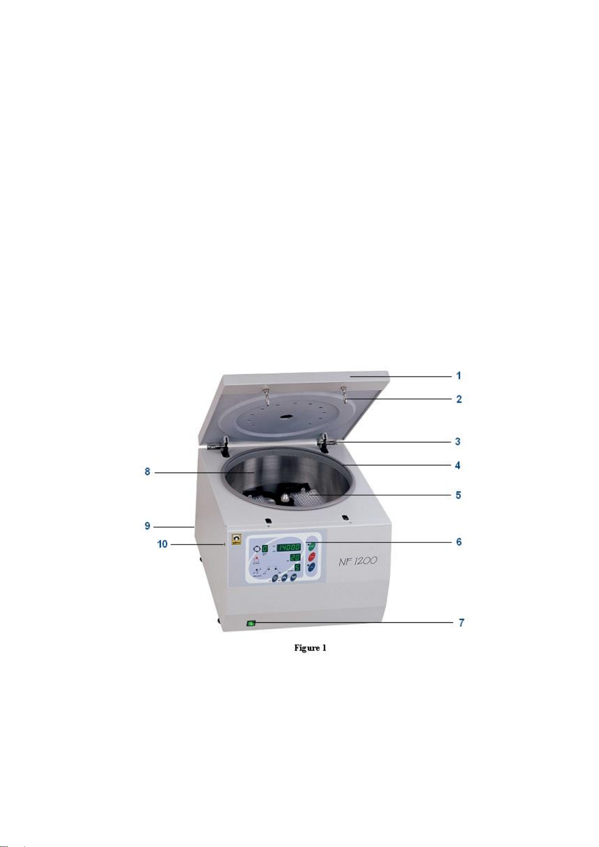
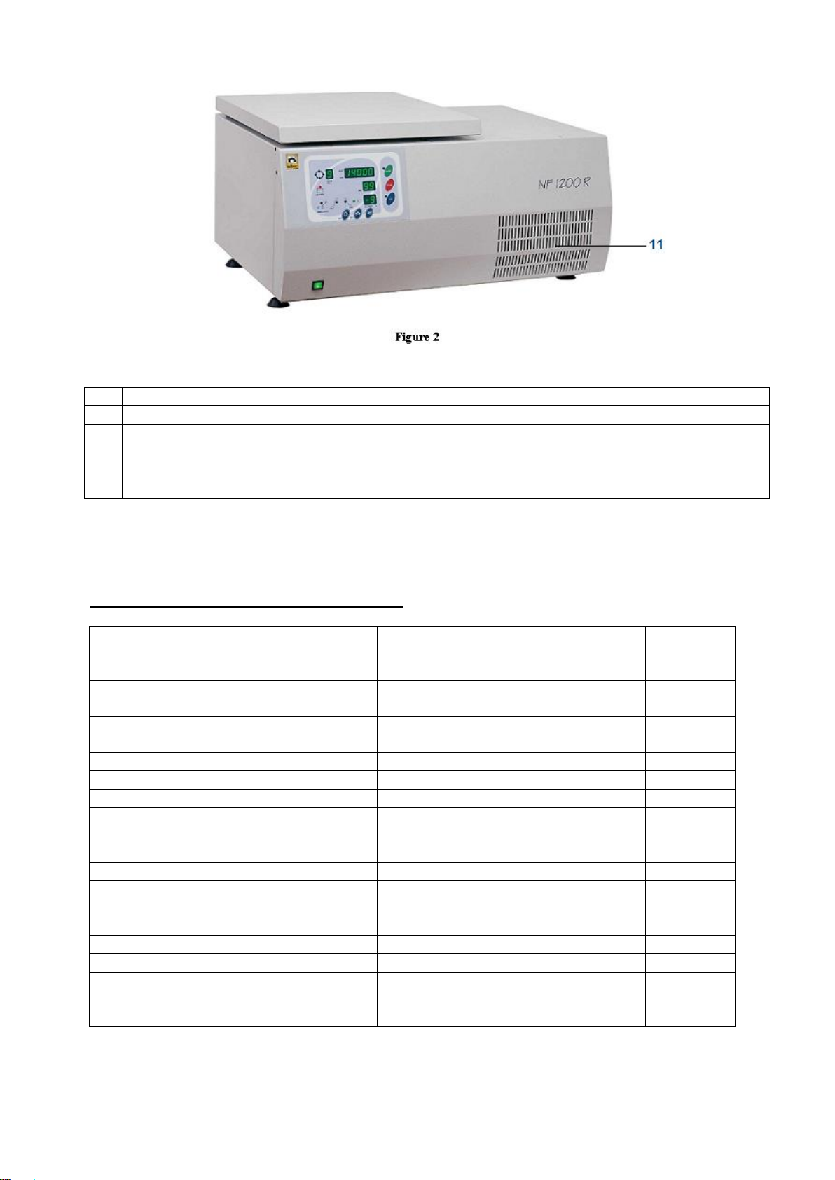
2.3 GENERAL PRESENTATION...............................................................................................................6
2.4 ROTOR SELECTION TABLE ..............................................................................................................7
2.5 PRECAUTIONS AND USAGE LIMITATIONS.....................................................................................8
SECTION 3 ........................................................................................................................................................9
SYMBOLS .........................................................................................................................................................9
SECTION 4 ........................................................................................................................................................9
OPERATING UNIT ............................................................................................................................................9
4.1. OPERATING........................................................................................................................................9
4.2. DISPLAYS AND CONTROL PANEL..................................................................................................10
4.2.1. Introduction to Control Display Panel Components and Functions............................................10
4.3. MAKING ANEW PROGRAM.............................................................................................................11
4.4. RUNNING THE PROGRAM ..............................................................................................................13
4.4.1. SELECTING THE MEMORIZED PROGRAM............................................................................13
4.5. SAFETY INTERLOCK SYSTEM........................................................................................................14
4.6. IMBALANCE DETECTION SYSTEM.................................................................................................14
4.7. MANUAL LID OPENING....................................................................................................................14
SECTION 5 ......................................................................................................................................................15
OPERATING PRINCIPLES.............................................................................................................................15
5.1. PREPARATION OF THE ROTORTO RUN.......................................................................................15
5.2. LOADING...........................................................................................................................................15
5.3. ROTOR INSTALLATION ...................................................................................................................16
5.4. DRIVE SYSTEM................................................................................................................................17
SECTION 6 ......................................................................................................................................................17
CLEANING AND PERIODIC MAINTENANCE ...............................................................................................17
6.1. PERIODIC MAINTENANCE..............................................................................................................17
6.2. STERILIZATION................................................................................................................................17
6.3. CORROSION INFORMATION ..........................................................................................................17
6.3.1. Chemical Corrosion....................................................................................................................18
6.4. STRESS CORROSION............................................................................................................................18
6.5. CLEANING ........................................................................................................................................18
6.6. ELECTRICITY ...................................................................................................................................18
SECTION 7 ......................................................................................................................................................19
DISPOSAL MANAGEMENT CONCEPT.........................................................................................................19
SECTION 8 ......................................................................................................................................................19
TROUBLESHOOTING.....................................................................................................................................19
SECTION 9 ......................................................................................................................................................20
ELECTRICAL CIRCUIT DIAGRAMS..............................................................................................................20
9.1. ELECTRICAL CIRCUIT DIAGRAM OF NF 1200...................................................................................20
9.2. ELECTRICAL CIRCUIT DIAGRAM OF NF 1200R ............................................................................21
SECTION 10 ....................................................................................................................................................22
WARNING LABEL...........................................................................................................................................22

4
SECTION 1
INTRODUCTION
1.1 USE AND FUNCTION
The NF 1200 / NF 1200 R centrifuges are designed to separate liquids of different densities by
applying centrifugal force. Different types of rotors, which are swing-out and angle rotors, can be
fitted to the centrifuges.
The microprocessor control system of the centrifuges enables the user to observe and to control
the speed (RPM or RCF), the acceleration and braking rates, run time, program number and
temperature of the bowl for NF 1200 R. The microprocessor control system also displays the RPM
or RCF value during the run.
The ventilation system of the NF 1200 limits temperature in the bowl between the ambiant
temperature + 3 °C and ambiant temperature + 12 °C depending on the rotor type. The NF 1200 R
is equipped with a cooling system which provides to operate between -9 °C and + 40 ° C.
It ensures safe processes by means of the locking system which does not allow the centrifuge to
operate if the lid is open and which does not allow the rotor to spin if the lid is not closed.
The lid locking system which does not allow the centrifuge to operate if the lid is open, which also
does not allow the lid to be opened while the rotor is spinning and the possibility to open the lid by
pushing only one key when the program ends, provide safe and easy working conditions. There
are audible and visible alarms to inform the operator when the lid is open, when the program ends
and when any error conditions occur. In case of a power failure, the lid could be opened manually
by using a manual lid opening tool
The NF series centrifuges are manufactured according to the following standards,
EN 61010-1, EN 61010-2-020, EN 61000-6-3, EN 50419.
This device is in compliance with WEEE Regulation.

5
SECTION 2
TECHNICAL SPECIFICATIONS
2.1 TECHNICAL SPECIFICATIONS TABLE
NF 1200
NF 1200 R
Max Speed
RA 280 rotor: 4100 rpm, MP 200 rotor: 4100 rpm,
RS 600 rotor: 9000 rpm, RS 100 rotor: 12000 rpm, RS24 rotor: 14000 rpm,
RS 30 rotor: 13500 rpm
Max. RCF
RA 280 rotor: 3082 x g, MP 200 rotor: 2349 x g, RS 600 rotor: 8965 x g, RS
100 rotor: 14167, RS24 rotor : 18405 x g, RS 30 rotor: 20170 x g
Max. Capacity
RA 280 rotor: 4x280 ml, MP 200 rotor: 2x3 microtitre plates,
RS 600 rotor: 6x100 ml, RS 100 rotor: 10x10 ml, RS 24 rotor: 24x1.5/2 ml,
RS 30 rotor: 30x2 ml
Control System
Microprocessor controlled
Display
High Visibility Digital
No. of Memories
10
Speed Range
500-14000 rpm
Speed Step
10 rpm
Speed Accuracy
± 20 rpm
Timer Range
01-99 min + Hold Position
Timer Step
1 min
Acceleration Rate
0: Slowest 9: Fastest
Braking Rate
0: Slowest 9: Fastest
Power supply
230 V, 50 Hz
Temp. range
-9° C / 40 ° C
Refrigerant Liquid
R134a
Temp. Accuracy
1°C
Temp. Performance
(at maximum speed) ambiant temp+12°C
+4°C at max. speed
Max. Power
500 W
800 W
Ext. Dimension
455 x 545 x 400
770 x 540 x 400
Packing Dim.
600 x 530 x 470
870 x 650 x 550
Net / Gross Weight
42 / 47 kg
75 / 80 kg
2.2 ACCESSORIES FOR NF 1200/1200R
A 08 062
Puller for rotor removal
B 50 016
RA 280 swing- out rotor 4*280 ml , 4.100rpm , 3.082 x g
G 51 007
Set of 4 buckes for RA 280
G 51 036
Set of 4 buckets with sealing cap
G 51 008
Set of 4 insert 1x280 ml
G 51 009
Set of 4 insert 1x250 ml flat
G 51 010
Set of 4 inserts 1x200 ml flat
G 51 011
Set of 4 inserts 1x100 ml
G 51 012
Set of 4 inserts 2x50 ml conical
G 51 013
Set of 4 inserts 4x25 ml
G 51 014
Set of 4 inserts 2x15 ml conical

6
G 51 015
Set of 4 inserts 12x15 ml
G 51 016
Set of 4 inserts 12x5/7 ml
G 51 017
Set of 4 inserts 19x5 ml RIA
B 50 021
MP 200 microtitre rotor 4.100 rpm 2.349 xg
B 50 023
RS 600 Angle rotor 6x100 ml 9.000 rpm , 8.965 xg
G 51 018
Set of 6 adaptors 1x50 ml
G 51 019
Set of 6 adaptors 1x50 ml cocinal
G 51 020
Set of 6 adaptors 1x30/38 ml
G 51 021
Set of 6 adaptors 1x15 ml cocinal
B 50 022
RS 100 Angle rotor 10x10 ml 12.000 rpm ,14.167xg
G 51 022
Set of 6 adaptors 1x6 ml
G 51 023
Set of 6 adaptors 1x1.5/2 ml
B 50 014
RS 24 Angle rotor 24 x1,5/2 ml 14.000 rpm , 18.407xg
A 14 005
Adaptor 500/800 µl
A 14 006
Adaptor 200 µl PCR
A 14 007
Adaptor 250/400/700 µl
2.3 GENERAL PRESENTATION

7
1
LID
7
On / off switch
2
Lock pin
8
Bowl
3
Gas spring
9
Electrıcal cables inlet and fuses
4
Gasket
10
Manual LİD opening hole
5
Rotor
11
Cooling unit
6
Dısplay and conrol panel
2.4 ROTOR SELECTION TABLE
SWING-OUT ROTORS AND ACCESSORIES
Rotor
Description
Capacity
Max.Tube
Dia.(mm)
Radius
(mm)
Max. Speed
(rpm)
Max.RCF
xg
RA280
Swing-out
Rotor
4x280ml
164
4,100
3,082
Set of 4
buckets
380 ml
nominal
76
Set of 4 inserts
1x280ml
65
Set of 4 inserts
1x250ml flat
62
Set of 4 inserts
1x200ml flat
55
Set of 4 inserts
1x100ml
39
Set of 4 inserts
2x50ml
conical
30
Set of 4 inserts
4x25ml
25
Set of 4 inserts
5x15ml
conical
17
Set of 4 inserts
12x15ml
17
Set of 4 inserts
12x5/7ml
13.5
Set of 4 inserts
19x5ml RIA
13
MP200
Microtitre Plate
Rotor
2 x 3
microtitre
plates
125
4,100
2,349

8
ANGLE ROTOR ACCESSORIES
Rotor
Description
Capacity
Max.Tube
Dia(mm)
Max.Radius
(mm)
Max.Speed
(rpm)
Max
RCFxg
RS600
Angle Rotor
6x100ml
38
99
9,000
8,965
Set of 6 adaptors
1x50ml
30
Set of 6 adaptors
1x50 ml conical
30.5
Set of 6 adaptors
1x30/38ml
26
Set of 6 adaptors
1x15 ml conical
17
RS100
Angle Rotor
10x10ml
16
88
12,000
14,167
Set of 10
adaptors
1x6ml
13
Set of 10
adaptors
1x1.5/2ml
11
RS24
Angle Rotor
24x1.5/2ml
11
84
14,000
18,405
Adaptor
1x500/800µl
8
Adaptor
1x200 µl PCR
6.5
Adaptor
1x250/400/700
µl
6
RS30
Angle Rotor
30x2ml
11
99
13.500
20.170
Adaptor
1x500/800µl
8
Adaptor
1x200 µl PCR
6.5
Adaptor
1x250/400/700
µl
6
2.5 PRECAUTIONS AND USAGE LIMITATIONS
Do not use the device for any purpose other than the usage purpose.
Prior to first use, the user’s manual should be read and the device is only to be used by
authorized and trained personnel. Only authorized technical personnel handle the product in
case of any failure.
The working bench should be durable to the device weight and vibration isolated.
Ensure that the rotor is placed correctly prior to usage.
According to the standard IEC 61010-2-020, anyone and any hazardous materials should not
be in the 300 mm safety zone while centrifuge is running.
Do not move the device while it is running.
Do not open the lid while rotor is spinning.
Apply the manual lid opening procedure in the case of power cut or in the case of any error.
Use only the the spare parts, rotors and accessories which are supplied by NUVE.
Load the rotor according to the explanations in the user’s manual.
Start the device after ensuring the rotor is loaded correctly.
Do not use the centrifuge in areas which are in explosive danger.
Do not centrifuge the explosive, flammable, radioactive, corrosive materials and the materials
which may react with each other.
The centrifuge and the rotor are not microbiologically leak-proof. Use tubes with leak-proof
covers, if hazardous, toxic and pathogenic microorganisms are centrifuged.
Do not use corrosive materials which may be harmful for the device integrity, rotor and
accessories.

9
Do not use rotors and accessories with corrosion and mechanical damages.
Mains supply should be appropriate to power of the device and grounded.
Use tubes whose sizes are suitable to the rotor and accessories.
Tubes which are used in the centrifuge should not be deformed by the effect of the centrifuge
force.
Use glass tubes to balance, if glass tubes are used. Use plastics tubes to balance, if plastics
tubes are used.
Do not start the device unless tubes are in balance.
Imbalance loading may cause mixing the samples, broken tubes, and damages on the rotor
and motor shaft.
IF MENTIONED WARNINGS ARE NOT CONSIDERED, NÜVE WILL NOT BE RESPONSIBLE
FROM THEIR RESULTS.
SECTION 3
SYMBOLS
Symbol in the operating instructions:
Attention, general hazard area.
This symbol refers to safety relevant warnings and indicates possibly dangerous
situations.
The non-adherence to these warnings can lead to material damage and injury to
personal.
Symbol in the operating instructions:
This symbol refers to important circumstances.
SECTION 4
OPERATING UNIT
4.1. OPERATING
Open the lid and check that there is no sample in the instrument.
Turn the centrifuges on by using On/Off switch.
See that the display and control panel activates.
Learn the functions of the control panel (See Part 4.2.1).
Set the values and start the operation (See Part 4.3)

10
4.2. DISPLAYS AND CONTROL PANEL
Şekil 3
4.2.1. Introduction to Control Display Panel Components and Functions
01- Speed Display
Display of speed (500-14.000 rpm) or display of RCF (0-18.405 x g) during the run and rotor
type during programming.
02-Time Display
Display of the run time from 1 min. to 99 min. and hold position (H).
03- Acceleration/Brake/Temperature Display
Display of the acceleration and brake rates from 0 to 10, for NF 1200 R it also displays the
bowl temperature during programming and the run.
04-Program No Display
Display of the program number from 0 to 9.
05- Running indicator leds
The 4 leds light up consecutively during the run to indicate the spinning of the rotor.
06- START key
Starts the centrifugation run.

11
07-STOP key
Stops the run by starting the braking phase manually.
08- LID key
Opens the lid if the lid indicator lights up.
09- LID Indicator Led
This led is on if the opening of the lid is possible.
10- START Indicator Led
This led turns on as the start button is pushed and turns off as the “Lid Indicator”(9) turns on
after the rotor has stopped spinning.
11-LID OPEN Indicator Led
It turns on if the lid remains open or is not properly closed.
12- Imbalance Indicator Led
It is activated if imbalance occurs. Brake is applied immediately.
13- Acceleration Indicator Led
It turns on while the acceleration rate is being programmed and while the rotor is accelerating.
14- Braking Indicator Led
This indicator turns on while the breaking rate is being programmed and while the rotor is
breaking.
15-Value Increase/Decrease Keys
They increase or decrease values during programming stage and to select the program
number during stand-by position. By pushing value increase key it is possible to see the set
values during centrifugation.
16- Function key
It is pushed to see the RPM or RCF value on the speed display during the run, to pass among
the displays and to store the programmed values.
17- Cooling Indicator Led*
It indicates that the cooling system functions. During programming, it indicates that the
temperature value is being set on Acc/Br/Temp Display (3).
* It is not valid for NF 1200 model.
4.3. MAKING A NEW PROGRAM
Determine the rotor type, the speed and time, the acceleration and braking rates.
Push the function key (16) once and see that the value on the program no display (4) flashes.
Enter the program number by pushing the value increase and value decrease keys (15).
Push the function key (16) again and see that the value on the speed display (1) flashes.
Select the proper rotor type by pushing value increase and value decrease keys (15).

12
ROTOR TYPE
DISPLAY
MAXIMUM
SPEED
(RPM)
MAXIMUM
SPEED
(RCF)
RA 280 Swing Out
S out
4,100
3,082
MP 200 Swing Out
PLAtE
4,100
2,349
RS 600 Angle
6 50
9,000
8,965
RS 100 Angle
10 10
12,000
14,167
RS 24 Angle
24 1.5
14,000
18,406
Angle Rotor Swing-out Rotor
NOTE :
The correct rotor type should be selected in order to see the correct RCF values
during the run.
Push the function key (16) and see that the RPM or RCF option on the speed display (1)
flashes. Choose the RPM or RCF option by pushing value increase and value decrease keys
(15).
Push the function key (16) and see that the value on the speed display (1) flashes. Enter the
run speed or RCF by pushing value increase and value decrease keys (15).
Push the function key (16) and see that the value on the time display (2) flashes. Enter the run
time by pushing the value increase and decrease keys (16). (H means hold position)
Push the function key (16) and see that the acceleration led turns on and the value on the
temperature display (3) flashes. Choose the acceleration value among 0,1,2,3,4,5,6,7,8 or 9 by
pushing the value increase and decrease keys (15).
(0: slowest 10: fastest rates)
Push the function key (16) and see that the break led turns on and the value on the
acc/break/temperature display (3) flashes. Choose the break value among 0,1,2,3,4,5,6,7,8 or
9 by pushing value increase and decrease keys.(0: slowest 9: fastest rates)
Push the function button (16) and see that the cooling indicator led (17) turns on and the value
on the acc/break/temperature display (3) flashes. Enter the bowl temperature value. (This step
is not valid for NF 800 model.)
Push the function key (16), the entered values will be saved.
You may make 10 (0-9) different programs.

13
4.4. RUNNING THE PROGRAM
Switch on the centrifuge, see that the on/off switch led turns on.
See that the control panel activates.
Load your samples to the rotor and close the lid.
You can run the centrifuge in two different ways,
You can make a new program (see section 5.3)
You can select a program from the memory
PRE-COOLING
While operating the NF 1200 R centrifuge at sub-ambient temperatures, in order to get the
maximum performance, without loading the rotor run the centrifuge at 1.500 rpm, at a temperature
which is 3° C lower than the required temperature and at hold position until you see that the
temperature inside the bowl drops to the required temperature. Then, stop the centrifuge, load your
samples and start centrifugation.
4.4.1. SELECTING THE MEMORIZED PROGRAM
Select the requested program number at stand-by position by pushing value increase and
decrease keys. All values related to the selected program will be shown on the relevant displays.
Check that all values are correct.
Load the rotor with samples by paying attention to the dynamic and static balances.
Close the lid, see that the lid open warning led (11) turns off.
Push START key (6) and see that the start led (10) turns on.
The rotor starts accelerating according to the set value and the acceleration led turns on. The
set speed or RCF value is displayed during the set time duration. (RPM or RCF screen will
appear in every 3 seconds). For the operations whose speeds are higher than 2.000 rpm, the
rotor accelerates according to the set acceleration value up to 2.000 rpm and then continues
accelerating with the highest acceleration value, 9 to reach the set speed. As the speed
reaches the set value, “-“ sign appears on the acc/brk/temp display (3). (The NF 800 R shows
the bowl temperature on the acc/brk/temp display until the centrifugation ends)
The elapsed time is counted down as the centrifugation starts.
When the time display shows “00”, the program ends, the breaking led turns on and the set
break rate is shown at acc/brk/temp display (3). The rotor brakes with the highest break rate, 9
until it slows down to 2.000 rpm and continues braking according to the set braking value.
The elapsed time until the rotor stops is counted and is shown at the time display. This is the
time that passes until the rotor stops.
When the speed display shows ”0000”, the start led (10) turns off, the “end” expression
appears and the lid led (9) turns on. The user is warned by an intermittently sounding alarm.
Push the LID button (8) to open the lid.
You may leave the centrifuge at stand-by position.
NOTE 1 :
You may display the RPM or RCF value on the speed display during the run by
pushing the function button.
NOTE 2 :
You may see all set values during the run by pushing the value increase key.

14
NOTE 3 :
At hold position, the rotor keeps spinning until the STOP key (7) is pushed.
After the STOP has been pushed, the rotor brakes according to the set brake
rate,
NOTE 4 :
The centrifuge waits at the stand-by position with the program values of the
last program.
NOTE 5 :
Please open the lid after every operation, otherwise the centrifuge cannot be
run again.
4.5. SAFETY INTERLOCK SYSTEM
The safety interlock system prevents opening of the lid when the rotor is spinning.
The centrifuge does not operate until the lid is closed and the lid remains locked until the rotor
stops spinning. The “Lid Open” indicator turns on to warn the user if the lid is not closed properly.
NOTE:
If power failure occurs, access to the samples is possible by opening the lid with a special
tool. Please see the manual lid opening section (3.6.) for further information.
4.6. IMBALANCE DETECTION SYSTEM
The imbalance detection system of the NF 1200 / NF 1200 R centrifuges operates
electronically when an unacceptable imbalance occurs. In this case the brake is applied
immediately.
The “Err 1” imbalance error is displayed and the imbalance indicator turns on. The lid can not
be opened until the rotor stops spinning. The centrifuge can only be started after the lid has
been opened and the rotor has been re-loaded correctly.
To avoid facing imbalance problem, please make sure to insert the tubes correctly.
4.7. MANUAL LID OPENING
In case of power cut or any breakdown, the centrifuge can be opened manually to access the
samples.
To open the lid manually:
Switch off the instrument.
Insert the manual lid opening tool into the hole on the left side of the instrument (see the
general view drawing).
Push the tool keeping it horizontal until the lid opens.
WARNING !!!
Before opening the lid manually, make sure that the rotor already stopped spinning. Upon opening
the lid, lift it by hand and observe the rotor. If the rotor is still spinning, close the lid and wait
approximately 10 minutes before repeating the operation. This operation must be carried by
someone who is informed of the danger and of the precautions which must be undertaken.

15
SECTION 5
OPERATING PRINCIPLES
5.1. PREPARATION OF THE ROTOR TO RUN
Before installation, check the rotor for corrosion and cleanliness.
Chemical corrosion or mechanical corrosion may do severe damage to the rotor and the
centrifuge. Particles which are stuck inside the inserts cause the breakage of tubes and lead to
major imbalance please check to make sure that no particles are left on the rotor.
The central hole of the rotor and the motor shaft should also be clean and dry before all
centrifugal operations and they must be kept in that way all the time.
5.2. LOADING
The most important condition of an efficient centrifugation is to balance the tubes properly. Loading
must be done by meeting the requisites of static and dynamic balance.
Static Balance: This balance states that diametrically oppositely replaced weights are almost the
same. In application, the liquid level in the tubes should be at the same height to balance the load.
Dynamic Balance: This balance states that diametrically oppositely replaced center of the gravity
of tubes are symmetrical with respect to spinning axis of the rotor.
Although in hospitals the samples having almost the same densities are centrifuged, in
industry, samples having different densities may be centrifuged. In this case, the dynamic
balance becomes more important factor than the static balance is.
If the number of tubes to be centrifuged is less than the capacity of the rotor, the tubes must be
placed oppositely. If an odd number of tubes is centrifuged, a water filled tube at the same
weight should be used for balancing.
Imbalance of the rotor may cause major damage to the rotor and centrifuge.
Never attempt to introduce liquids into the tube inserts.
Balance the rotor with glass tubes if you use glass tubes for centrifugation.
Balance the rotor with plastic tubes if you use plastic tubes for centrifugation.
Always use tubes which can withstand to the set speeds.
Examples of the proper and improper loading are shown below.

16
Figure 3
NOTE: Distribution of the load is more important than the load itself.
5.3. ROTOR INSTALLATION
Put some light oil on the drive head to prevent sticking.
Be careful that the rotor fits on the drive shaft (See Figure 4).
Screw the shaft nut with socket wrench to the clockwise direction. Make sure that shaft nut is
screwed tightly, but do not expose over-force to the socket wrench while screwing.
For swing-out rotors, lubricate the pins where the buckets are hanged.
Place the buckets to the rotor.
Connect the centrifuge to the power supply.
Figure 4

17
5.4. DRIVE SYSTEM
The rotor is driven by a three phase asynchronous motor. The microprocessor control system
assures the correct drive speed.
The force applied to the rotor is directly related to the shape of the rotor, the swing-out rotor
receives more load than the angle rotor does. Longer radius and more accessories increase
the load of the rotor and decrease the spinning speed.
The centrifuge does not allow the rotor to spin at a speed which it cannot resist mechanically.
Please make that sure the correct type of rotor is selected during programming.
SECTION 6
CLEANING AND PERIODIC MAINTENANCE
6.1. PERIODIC MAINTENANCE
Disconnect the power cable and after the maintenance check the presence of the mains
grounding line.
Rotors should be washed after every use, especially if a spillage has occurred, in warm water
containing a few drops of liquid soap. (A mild washing liquid is ideal as a cleaner).
Rotors and other accessorıes must be clean if any spillage or chemicals occur.
You may use a nylon brush to clean the buckets and tube inserts of the rotor.
Do not use metal brushes.
Dry the rotor with a piece of soft absorber cloth. Please make sure that the buckets and inserts
are well dried, you may use hair dryer.
The buckets of the swing-out rotors should be greased frequently with the oil provided with the
centrifuge. Please remove the light oil from the pins and put a small amount of fresh oil every
time you grease. This will ensure free swinging of the buckets. Most of the imbalance problems
are mostly raised by the users who do not clean and oil the pins.
Please do not leave the rotor on a metal surface, particularly stainless steel as electrochemical
reactions set off easily with the aluminum or magnesium in the rotor.
Make sure that no deposit remains at the bottom of the bucket because the pressure of a flask
or tube from above during centrifugation will certainly increase the chance of corrosion.
6.2. STERILIZATION
Apply alcohol, for example %70 ethanol or isoprophanol, for 10 minutes against bacteria and
viruses.
The rotors and buckets may be autoclaved at 121°C and under 215 kPa pressure for 20
minutes but please do not forget to remove all accessories.
Do not use formaldehyde for the sterilization process.
Phenol is a corrosive substance and should never be used.
Glutaraldehyde is a toxic substance and increases the rate of fatty acid in the body.
6.3. CORROSION INFORMATION
Nuve rotors which are made of aluminum are designed to spin at proper RCFs for many years.
When used properly, their resistance to corrosion and their life span increases and the
imbalance problems decrease.
All accessories should be checked thoroughly and regularly as almost all laboratories already
have the conditions which lead to corrosion easily.

18
6.3.1. Chemical Corrosion
This type of corrosion is caused by chemical reactions. The electrolide liquid on the surface of the
material is the main cause of the chemical reaction. If that electrolide liquid is allowed to stay at
the surface, corrosion occurs. First, discoloration appears and then the metal pittens. Aluminum
easily reacts with the ionic solutions.
The other causes of corrosion are as follows,
Chemical vapors in the laboratory environment which dissolve in the water on the rotor (in
refrigerated centrifuges)
Corrosive liquids which overflow from overfilled and unsealed tubes. (the liquids which spread
out during centrifugation)
Contaminated and non-cleaned buckets, tubes and bottles.
NOTE:
If the centrifuged samples are corrosive, only rinsing with water is not sufficient. The
residuals dissolve in the water and humidity on the rotor and in the buckets.
NOTE:
Some particles may stick to the tubes, buckets and adapters. These particles crash and
do harm to anodized surface during centrifugation and ease the occurrence of
corrosion.
6.4. Stress Corrosion
This type of corrosion is caused by the force of the centrifugation of the corrosive chemical which is
already in contact with the alloy. As the aluminum alloy contacts with the corrosive chemical, the
stress corrosion starts. This type of corrosion is even more dangerous than the chemical corrosion
as the effects of this corrosion are microscopic and very difficult to observe in the course of time.
The corrosive material is pushed against the aluminum alloy by the centrifugation “g” force during
the centrifugation. This situation causes the stress corrosion to occur more quickly than the
chemical corrosion does. Microscopic cracks occur under the force of the centrifugation.
Every centrifugation causes the aluminum rotor to be attacked by the chemical more and more and
eventually micro-cracks decrease the resistance of the rotor against the centrifugation force.
Fortunately, no crash occurs just after the first micro-cracks have appeared as the rotors are
manufactured according to the high safety limits.
The corrosion of the small amount of corrosive materials does not result in severe cracks but
weakens the mechanical resistance of the rotor in the course of time.
The rotor’s places, buckets, buckets’ edges and the base of the rotor should be checked regularly.
If needed, they must not be used until a specialist has checked them thoroughly.
6.5. CLEANING
Disconnect the centrifuge before cleaning.
There is no need of daily cleaning unless a tube breakage occurs or any liquid spills.
6.6. ELECTRICITY
Centrifuged at high voltages are present behind the panels. These panels are electrically
disconnecting Do not open the centrifuge

19
SECTION 7
DISPOSAL MANAGEMENT CONCEPT
The currently valid local regulations governing disposal must be observed. It is in the responsibility
of the user to arrange proper disposal of the individual components.
Applicable local regulations for disposal have to be carefully observed.
The instruments and electronic accessories (without batteries, power packs etc.) must be disposed
off according to the regulations for the disposal of electronic components.
Batteries, power packs and similar power source have to be dismounted from electric/electronic
parts and disposed off in accordance with applicable local regulations.
SECTION 8
TROUBLESHOOTING
If the centrifuge fails to operate,
Check that,
The on/off switch is on,
The fuses are sound,
The plug is not defective,
The centrifuge is well connected to the supply,
The electricity installation is not defective,
Power is supplied.
In case of below written failures, related error codes are shown,
Err 2
Motor overheat. Please switch off the centrifuge for at least 20 minutes
Err 3
Speed failure. The optical sensor could have failed. Please observe whether the “running”
indicator leds are on or not. If it is not on, the optical sensor is defective. If it is on, the motor
could have failed. Contact to your service if either occurs.
This error code occurs when the mains voltage drops below the lower limit.
Err 4
Lid failure. This failure occurs when lid is opened during the centrifugation.
Err 5
The temperature sensor endings are broken. This error code appears only on NF 1200R.
Err 6
Motor failure. The motor driver unit (inverter) is defective. Switch off the centrifuge and switch
on again after the motor has stopped. If you still see the error code, contact to the service.
PLEASE CONTACT TO AN AUTHORIZED NUVE AGENT TO SEEK TECHNICAL HELP IF AN
ERROR OCCURS.
This manual suits for next models
3
Table of contents
Other NUVE Laboratory Equipment manuals
Popular Laboratory Equipment manuals by other brands

Biuged Laboratory Instruments
Biuged Laboratory Instruments BGD 626 instruction manual

Opentrons
Opentrons OT-2 Users manual & quick start guide

Barnstead International
Barnstead International Harvey Hydroclave MC8 Owner's and operator's manual

Julabo
Julabo 200F Original operating manual

Beckman Coulter
Beckman Coulter CytoFLEX Instructions for use

Koehler
Koehler K18854 Operation and instruction manual