Novexx Solutions AP 4.4 User manual

04/09 Rev. 5.01-02 SERVICE MANUAL
AP4.4 – AP5.4 – AP7.t
Fault Location
Error sources ................................................ 2
Notes about fault location .......................... 2
Data transmission ..................................... 2
Display ...................................................... 2
Gap detection ............................................ 2
Material transport ...................................... 3
Ribbon, ribbon guide ................................. 3
Print roller .................................................. 3
Position of the print image .........................4
Print quality ............................................... 4
Plug-in card (AP5.4/AP7.t) ....................... 5
Cut function, cutter (AP5.4/AP7.t) ............ 5
Cut function, TCS (AP7.t) .........................6
Reading out diagnosis data ...........................7
Reading out via serial interface .................8
Storing on CF card ...................................10

04/09 Rev. 5.01-02 SERVICE MANUAL Fault Location
AP4.4 – AP5.4 – AP7.t
2
Error sources
Notes about fault location
Status reports should be printed to check the mechanical and electronic function
capabilities – provided that no obvious no defectives are evident.
Data transmission
Display
Gap detection
Problem Possible cause Solution
No or damaged data Faulty data cable Check, if the right data cable is applied
Wrong interface selected Check, if parameter INTERF. PARAM.>
EASYPLUGINTERPR> Interface is set correctly
Setting of transmission
parameters incorrect
Check, if the transmission parameters forthe
selected interface are set correctly (not for
Centronics)
Faulty pin assignment of
the data cable
Change or replace data cable. The pin as-
signment of the interfaces can be found in
topic section „Service Electronics“, chapter
„CPU board“, „Connectors“.
Incorrect handshake
signals Check parameter setting (only for serial inter-
face)
Selection Select standard character set
CPU board defective Check and if necessary replace CPU board
Permitted cable length
exceeded Do not exceed cable length
[Tab. 1]Possible faults caused by data transmission
Problem Possible cause Solution
Display dark Plug connector loose Check and if necessary plug in again
Display defective Check and if necessary replace display
CPU board defective Check and if necessary replace mainboard
Button function faulty
Plug connector loose Check and if necessary plug in again
Buttons defective Check and if necessary replace buttons or
display board
CPU board defective Check and if necessary replace mainboard
[Tab. 2]Possible faults at the display
Problem Possible cause Solution
Gap detection not
possible
Photoelectric switch defec-
tive Check with SERVICE FUNCTION> Sensor test, if
necessary replace the photoelectric switch
Photoelectric switches set
incorrectly Use parameter SYSTEM PARAMETER >
Sens. punch-LS to alter sensitivity
False photoelectric switch
selected Select "Punched" or "Reflex" using the pa-
rameter SYSTEM PARAMETER > Light sens. type
[Tab. 3]Possible faults caused by the gap detection

04/09 Rev. 5.01-02 SERVICE MANUAL Fault Location
AP4.4 – AP5.4 – AP7.t
3
Material transport
Ribbon, ribbon guide
Print roller
Print position shifted
in or against print di-
rection
Gap position not recog-
nised consistently due to
gap contour
Correct photoelectric switch zero line using
parameter PRINT PARAMETERS > Punch offset
Problem Possible cause Solution
[Tab. 3]Possible faults caused by the gap detection
Problem Possible cause Solution
Material guide (green
part) loosens Friction is set to low
Modify the setting. Instruction see service
manual, topic section Service Mechanics ,
chapter „Material transport“, „Setting the fric-
tion of the material guide“.
No feed function
Stepper motor plug loose Check and if necessary plug in
Stepper motor defective Check and if necessary replace motor
CPU board defective Check and if necessary replace mainboard
Feed button defective Check and if necessary replace display board
Jolted print image Material unwinder blocked Check and if necessary loosen
Material shifts Material guide set
incorrectly Check and if necessary set
[Tab. 4]Possible faults caused by material transport
Problem Possible cause Solution
Unfounded ribbon
end message Ribbon unwind mandrel is
not turned Fix core to mandrel (spring plate), shift spring
plate if the thread has stripped.
Photoelectric switch defec-
tive Check and if necessary replace (see also pa-
rameter SERVICE FUNCTIONS> Sensor test)
Ribbon produces
folds
Ribbon guiding plate at the
printhead adjusted incor-
rectly
Check and readjust positioning of the guiding
plate
Ribbon is not being
rolled up Ribbon core slips through Fix core to mandrel (spring plate), shift spring
plate if the thread has stripped.
Toothed belt defective Check and if necessary replace the belt
Ribbon tears during
printing process Printhead temperature is
too high
Check setting of print contrast (press Prog.
button in on-line mode or parameter
PRINT PARAMETER > Printcontrast) and if neces-
sary correct.
[Tab. 5]Possible faults caused by the ribbon guiding
Problem Possible cause Solution
Wear High running performance Replace roller
Printhead pressure too high Check and if necessary correct
Material deposits Clean the roller
[Tab. 6]Possible faults caused by the Print roller

04/09 Rev. 5.01-02 SERVICE MANUAL Fault Location
AP4.4 – AP5.4 – AP7.t
4
Position of the print image
Print quality
Ink residue Ribbon prints directly on
feed roller Clean and prevent direct printing on roller
Deformation
Printing directly on roller Use sufficient wide material/foil
High running performance Replace roller
Power setting too high for
printhead
Check print contrast setting (press Prog. but-
ton in on-line mode or parameter
PRINT PARAMETER> Print contrast) and if neces-
sary correct.
Damage by operator Replace roller and draw attention to proper
care
Problem Possible cause Solution
[Tab. 6]Possible faults caused by the Print roller
Problem Possible cause Solution
Print position shifted
in or against print di-
rection
Incorrect parameter setting Check parameter PRINT PARAMETER> Y-Print
offset or Easy Plug command (#Jx), if neces-
sary correct
Gap position is recognised
incorrectly due to gap con-
tour
Correct sensor zero line with parameter
PRINT PARAMETER> Gap offset
Material unrolling blocked
or too sluggish Check and if necessary correct
Material guide set too
narrowly Check and if necessary set
Pressure rollers positioned
incorrectly or not at all Check and if necessary set
Print shifted at right
angles to document Material guide not set
correctly Check and if necessary set
[Tab. 7]Unsatisfactory print position and the possible reasons.
Problem Possible cause Solution
Print faded
Printhead dirty or defective
Clean or replace thermal bar.
¯Clean printhead regularly to ensure opti-
mal print head condition. It is recommended
this is done when replacing the roll of foil us-
ing cleaning paper (article number 5030).
Printhead setting incorrect Check settings (e.g. print contrast, print head
resistance) and alter if necessary
Ribbon and material not
aligned Check ribbon type and material type, if nec.
alter
Ribbon possibly super-
imposed Insert new ribbon
Poor or uneven print Print roller damaged or
soiled Check and if necessary clean or replace roller
[Tab. 8]Unsatisfactory print quality and the possible reasons

04/09 Rev. 5.01-02 SERVICE MANUAL Fault Location
AP4.4 – AP5.4 – AP7.t
5
Plug-in card (AP5.4/AP7.t)
Cut function, cutter (AP5.4/AP7.t)
Feed in order but no
print image
Printhead setting too low
Check setting print contrast (press Prog. but-
ton in on-line mode or parameter
PRINT PARAMETER> Print contrast) and if nec.
correct.
Ribbon inserted incorrectly
(colour side) Check and if necessary correct
Printhead not fixed to
bracket Fix thumb screw
Printhead defective Check printhead and if necessary replace it
Printhead cable not or in-
correctly plugged in Check and if necessary plug in again
CPU board defective Check and if necessary replace mainboard
Problem Possible cause Solution
[Tab. 8]Unsatisfactory print quality and the possible reasons
Problem Possible cause Solution
Plug-in cards are not
recognised
Contacts dirty Check and if necessary replace
Card defective Check and if necessary replace
Card type does not corre-
spond to approved type Check and if necessary replace
[Tab. 9]Possible problems with plug-in cards
Problem Possible cause Solution
No cutter function
Connector loose Plug in connector firmly.
Cutter function not activat-
ed Select and activate "Cutter" setting for param-
eter SYSTEM PARAMETER> Peripheral device
Photoelectric switch defec-
tive Check and if necessary replace switch
Stepper motor or output
stage board defective Check and if necessary replace
Material is only par-
tially cut or not cut at
all
Setting of cutter position Check photoelectric switch or position of os-
cillator disc and if necessary correct
Cutter blunt or dirty Check and if necessary clean or replace
Material problem Only use approved materials
Cut next to recog-
nised gap Gap detection Check setting for parameter
PRINT PARAMETER>Cut position and if neces-
sary correct the setting
Cut offset to impres-
sion Cutter position incorrect Check and if necessary set
Material moves
above or under cutter Unwinding too sluggish, roll
weighs too much Check and if necessary correct
Cutter cuts twice Double cut programmed Check setting of cut function (Parameter
Print Parameter> Double Cut)
[Tab. 10]Problems possibly caused by a cutter (if mounted).

04/09 Rev. 5.01-02 SERVICE MANUAL Fault Location
AP4.4 – AP5.4 – AP7.t
6
Cut function, TCS (AP7.t)
Problem Possible cause Solution
No function
Connector loose Plug in connector firmly.
TCS function not activated Select and activate "TCS" setting for parame-
ter SYSTEM PARAMETER> Peripheral device
Photoelectric switch
defective Check and if necessary replace switch
Stepper motor or output
stage board defective Check and if necessary replace
Cover open Check and if necessary close cover
Cover contact switch not
correctly adjusted Check and if necessary adjust
Material is only
partially cut or not cut
at all
Setting of motor light barrier Check light barrier or position of switch flag
and if necessary correct
Cutter blunt or dirty Check and if necessary clean or replace
Material problem Only use approved materials
Cut next to recog-
nised gap Gap detection Check setting for parameter
PRINT PARAMETER>Cut position and if neces-
sary correct the setting
Cut offset to impres-
sion Cutter position incorrect Check and if necessary set
[Tab. 11]Problems possibly caused by a TCS (if mounted).

7
04/09 Rev. 5.01-02 SERVICE MANUAL Fault Location
AP4.4 – AP5.4 – AP7.t
Reading out diagnosis data
With the diagnose dump function, device inter-
nal operation states can be read via serial con-
nectionandbesavedin atext file.Thisway,the
last device internal communication can be cap-
tured and analysed (comparable to the black
box in an airplane).
The function is helpful, if the device got in an
undefined state. This happened for example,
if…
•printing suddenly stops.
•the status message „unmanaged interrupt“
appears on the display.
•the device suddenly doesn´t react on key-
strokes any more.
In those cases, the log file is generated auto-
matically.
There are two ways of storing the log file:
•Reading out via the serial interface and
storing it on the host PC.
•Storing on CF card.
¯Alternatively, the log file can be read out us-
inganotherthantheserialinterfaceorusingthe
debug interface, see Easy-Plug manual,
#!XM command.
8
04/09 Rev. 5.01-02 SERVICE MANUAL Fault Location
AP4.4 – AP5.4 – AP7.t
Reading out via serial interface
Prerequisites
•Firmware (at least):
•Terminal program, e. g. „Hyperterminal“ (is
delivered with Windows operating sys-
tems).
Carrying out
1. Connect the printing device to a PC, using
the serial interface. Set the transfer param-
eters to 115kB, n, 8, 1 (default setting).
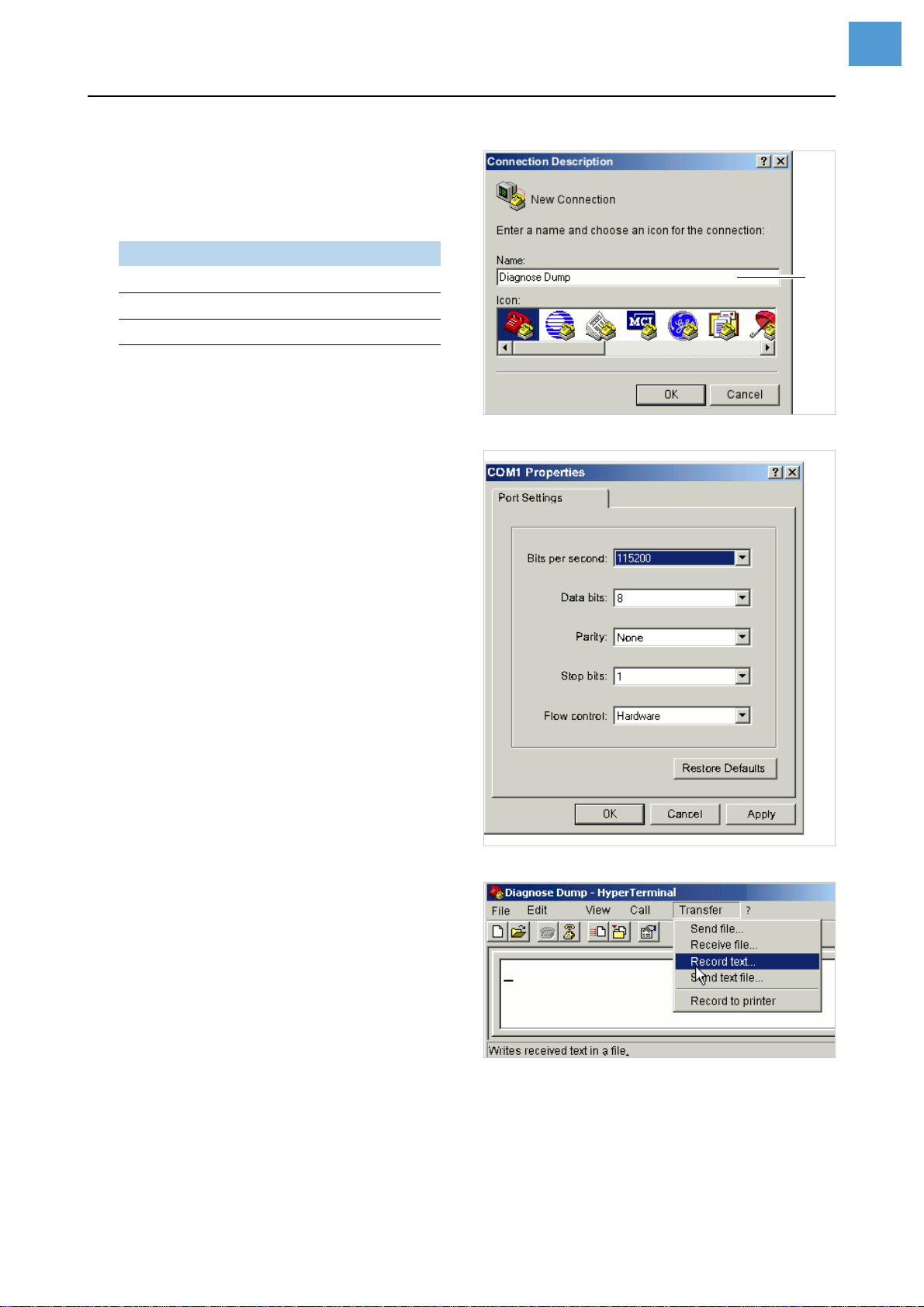
2. Start Hyperterminal.
The window „Connection Description“ [1]
opens.
3. Name the new connection [1A]. Click OK.
The window „Connect“ opens.
4. Select the serial port of the PC and click
OK.
Thewindow„COM1Properties“[2]opens(if
COM1 was selected).
5. Set the transfer parameters to
115kB, n, 8, 1 and click OK.
The Hyperterminal main window opens.
6. Open the menu „Transfer“ and click
„Record Text“ [3]. An input window opens.
Enter the file name for the record file and
click „Start“.
7. At the printer operation panel press all four
buttons simultaneously.
This starts data being read out of the print-
ing device and being displayed in the
Hyperterminal main window [4]. At the
same time, the data are saved in the record
file.
8. To stop the transmission, click „Cancel“ in
the menu „Transfer > Record text...“.
Generating further record files:
«Close Hyperterminal and start new.
Version Printing device
3.22 AP4.4 (16MB), AP5.4, AP7.t
4.22 64-xx Gen. 2, DPM, ALX92x
5.02 64-xx Gen. 3, PEM
[1] Enter a name (A) for the new connection.
[2] Set the transfer parameters.
[3] Hyperterminal main window.
A

9
04/09 Rev. 5.01-02 SERVICE MANUAL Fault Location
AP4.4 – AP5.4 – AP7.t
[4] Read out data.
«Send the generated files with a descriptioin
ofthe circumstancesinwhich theerror occured
per email to the technical support at Avery Den-
nison.

10
04/09 Rev. 5.01-02 SERVICE MANUAL Fault Location
AP4.4 – AP5.4 – AP7.t
Storing on CF card
Prerequisites
Firmware (at least):
Carrying out
1. Call SERVICE/DIAGNOS. > Diagnosis to CF.
The second line shows the initial 16 charac-
ters of the default file name. The complete
file name is:
„Diagnose AP 5.4 203 Dpi
A429403110613.log“
–AP 5.4 203 Dpi: Printer type and print-
head resolution
–A429403110613: Serial number of the
CPU board; equals the string in
SERVICE DATA > CPU BOARD DATA > Serial
number
2. Press the online button twice to acknowl-
edge and to store the file name.
Typing in a new file name:
1. Press the prog button to dismiss the default
file name.
2. Select each character of the new file name
by pressing the cut/feed buttons and ac-
knowledge it by pressing the online button.
3. Finally press the online button twice to ac-
knowledge and store the file.
¯Alternatively, type in the file name onan op-
tional keyboard connected to the printer and
acknowledge by pressing online.
The log file will be stored in the \LOGFILES di-
rectory on CF card.
Version Printing device
3.31 AP4.4 (16MB), AP5.4, AP7.t
4.31 64-xx Gen. 2, DPM, ALX92x
5.31 64-xx Gen. 3
Diagnosis to CF
Diagnose AP 5.4
Other manuals for AP 4.4
1
This manual suits for next models
2
Table of contents
Other Novexx Solutions Printer Accessories manuals


Popular Printer Accessories manuals by other brands


Star Micronics
Star Micronics TSP800 Series install guide

Citizen
Citizen CBM-202PC Series user manual

Canon
Canon Color imageCLASS MF8170c installation instructions

Codonics
Codonics Virtua 1VCX-LR833 Technical brief

Roland
Roland DU2-64 Supplementary manual

TonerRefillKits
TonerRefillKits ReChargX RX126 instructions