Page 2
Nomenclature
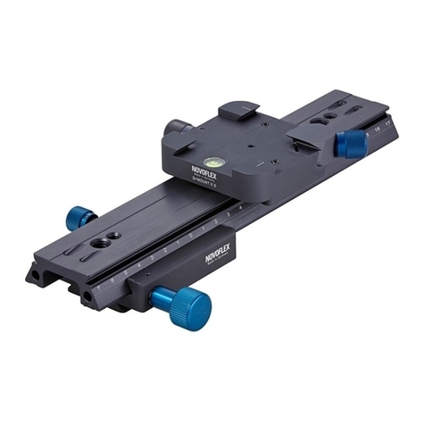
1 Locking knob 8 Setting scale
2 1/4“ Threaded hole, sliding block 9 3/8“ Threaded hole (2x)
3 Camera screw 1/4“, sliding block 10 1/4“ Threaded hole (3x)
4 Sliding block 11 Mounting hole
5 Drive knob 12 Threaded hole for video-pin, rail (2x)
6 Threaded hole video-pin, sliding block (2x) 13 Camera screw 1/4“, rail
7 Guideway holes for rods (accessories) 14 Cut-out for safety pin (4x)
Mounting
Attach to a tripod head or quick release
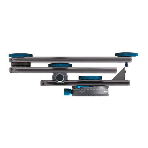
1. Classic assembly (Fig. 1)
The focusing rack is equipped with a dovetail guide for direct mounting on a NOVOFLEX
quick-release of the Q=System (ARCA / UNIQ/C compatible). The safety pin of a NOVOF-
LEX quick-release engages into the milling cut-out (14) and prevents unintentional slipping out
of the rack if the corresponding clamping screw was accidentally not fully tightened.
Alternatively, the 1/4 “or 3/8” threaded holes (10) or (9) can be used for mounting on a tripod
head. The installation of a video-pin (threaded hole 12) serves as anti-twist protection. In both
cases, the camera screw of the rail (13) could be in the way. We recommend turning this out.
1
8
5
6
3
2
4
Page 3
2. Inverted assembly (Fig. 2)
With this type of mounting, turn the camera screw (3) out with an Allan key, passing it through
the mounting hole (11). To do this, move the sliding block (4) with the drive knob (5) and open
locking knob (1) to a position just below a mounting hole (11). In the 3/8 “threaded hole sits an
1/4” adapter, which can be unscrewed if necessary.
Attaching the camera or other accessories (such as an bellows unit)
To mount the device on the sliding block (Classic assembly, Fig. 1) use the camera screw (3). To
do this, first move the sliding block (4) using the drive
knob (5) with open locking knob (1) to a position just be-
low a mounting hole (11). You will now have access to the
screw with the help of an Allen key that you pass through
the mounting hole (11) from below. You can also use the
threaded hole (2). If necessary, use the holes next to it
for a video-pin (6). If you mount inverted (Fig. 2), use
the camera screw (13) of the rail together with one of the
three 1/4” threaded holes (10). If necessary, a video-pin
can be used as well (hole 12) if your device supports it.
Operation
By turning the drive knob (5) with the locking knob
(1) open, move the sliding block (4) smoothly and
precisely forwards and backwards. By tightening the
locking knob (1), the sliding block (4) can be locked in
any desired position.
The focusing rack has a setting scale (8), which serves
as an adjustment aid in stereoscopic photography. In
addition, certain positions can be approached reproducibly, important e.g. in panorama photog-
raphy.
Safety Instructions
The locking knob (1) is used only for clamping the sliding block. It is not suitable for setting a fric-
tion (braking). If the drive knob (5) is moved in the clamped state, this can damage the cograil!
Do not try to drive beyond the end stop with the sliding block (4). This can also lead to damage
to the cograil! !
Please do not use grease for lubrication. It is recommended to keep the rack clean from sand
and dirt.
Fig. 1: Classic assembly
Fig. 2: Inverted assembly
