manuals.online logo
Brands
  1. Home
  2. •
  3. Brands
  4. •
  5. NOVOFLEX
  6. •
  7. Camera Accessories
  8. •
  9. NOVOFLEX TrioPod PRO 75 User manual

NOVOFLEX TrioPod PRO 75 User manual

TrioPod PRO 75
USER MANUAL
Congratulations on your acquisition of the TrioPod PRO75 – the new professional, sturdy
and versatile tripod. Whilst you should have no diculty in using the TrioPod PRO 75, you
may find the following explanations useful.
The TrioPod PRO75 is the most sturdy tripod with-
in the modularly constructed TrioPod series. The
load capacity was set to remarkable 65 kg / 163
lbs. Due to the reinforced construction of the
single components and the huge leg diameter,
the TrioPod PRO75 is especially suited for
heavy photo- and video equipment. The tri-
pod is supplied with the TRIOPRO C3930
set including the carbon fiber legs QLEG
C3930 (3 segments) or with the TRIO-
PRO C3940 set including the carbon
fiber legs QLEG C3940 (4 segments).
The upper tripod platform is equipped
with a 3/8“ stud screw for attach-
ment to most tripod heads (such
as the ClassicBall 5 II) and can be
replaced by the levelling base
MBAL-PRO75, the 75mm half
bowl adapter TRIO B-PRO75 or
the geared center column TRIO
CC-PRO75.
Compatible accessories from
other manufacturer can also
be used within the upper
standard socket.
Features and Accessories
TRIOPRO C3940
Information
For more information, advice and tips concerning our products contact your photo dealer,
the distributor of NOVOFLEX products in your country (have a look at “Where to buy“
section at our website to find your distributor) or visit our website: http://www.novoflex.com
For personal advice about possible accessories which is suitable for your NOVOFLEX
product please contact the following phone number or send us an E-mail.
NOVOFLEX Phone: +49 8331 88888
NOVOFLEX E-Mail: mail@novoflex.com
© NOVOFLEX Präzisionstechnik GmbH
Brahmsstraße 7
D-87700 Memmingen
Phone +49 8331 88888, Fax +49 8331 47174
Email mail@novoflex.com, Internet www.novoflex.com
Page 2
Monopod Conversion
Each leg can be unscrewed from the tripod
basis and converted (using the supplied QP
MONO plate) to a single monopod.
Interchangeable Feet
All legs are equipped with rubber feet
at its ends and can be replaced by stain-
less steel spikes (included in the scope
of delivery).
QP MONO
TRIOPRO C3940 with
TRIO CC-PRO75,
CB5 II and Q=BASE
TRIOPOD-PRO75
QLEG C3940
Accessory Ports
The tripod basis has, apart from the
leg connections, two side-on coun-
tersunk 1/4“ drilled holes (1) to attach
additional accessories with 1/4“ thread
screw such as the two Mini Legs (in-
cluded in scope of delivery) or flexible
gooseneck arms in order to mount
flash lights, microphones or reflectors.
Detent Angle Stops
For near-ground operation the tripod
basis is equipped with detent angle
stops for the purpose of spreading the
legs in predefined angles of 23°, 45°,
65° and 87°. An additional angle stop
at 155° enables to support the tripod
against a wall, for example in narrow
places like interiors. Furthermore the
tripod is equipped with an angle stop
for transport in standard position, in
order to carry the tripod comfortably
grabbing only one leg.
To achieve as low as possible packing
size the legs can be turned 180° and
grouped around the center column
with mounted tripod head.
1
1
Technical Data TRIOPRO C3930 and TRIOPRO C3940
• 3- respectively 4 section carbon ber legs, 8-layered
• Leg extension length: 60.5-161 cm (23.8-63.3 in.) respectively 50-161 cm (19.7-63.3 in.)
• Maximum working height: 154 cm (60.6 in.)
• Minimum working height: approximately. 5.5 cm (2.1 in.)
• Folded length (basis with legs, normal): 69 cm (27 in.) respectively 57 cm (22 in.)
• Max. load: 65 kg (143 lbs)
• Upper stud screw : 3/8“
• Lateral accessory ports: 2 countersunk 1/4“ drilled holes
• Leg angle stops: 23°, 45°, 65°, 87°, 155° and 180°
• Legs can be turned 180° for transport
• Leg diameter (mm): 39; 35.5; 31.5; 27.5 (1.5, 1.4, 1.2, 1.1 in.)
• Total weight 3205 g (7.066 lbs) respectively 3175 g (6.999 lbs)
• Rubber feet, which can be replaced by stainless steel spikes (included)
• Two interchangeable Mini Legs for the accessory ports, the Multi-Tool and a carrying
bag are included in the delivery
Technical Data 75mm half bowl adapter TRIO B-PRO75
• Weight: 74 g (0.16 lb.)
Height: 21 mm (0.8 in.)•
Diameter: 79 mm (3.1 in.)•
Technical Data levelling base MBAL-PRO75
• Weight: 500 g (1.1 lbs)
• Dimensions: 48 × 75 × 101 mm (1.9 x 2.6 x 4.0 in.)
• Diameter: 75 mm (2.9 in.)
• Tripod Connection: TRIOPOD-PRO75 tripod base plus 1/4 “and 3/8”
Camera Connection: turnable stud screw 1/4“ and 3/8“•
Adjustment range: +/- 15° in any direction•
Max. load: 20 kg (44 lb.)•
Technical Data geared center column TRIO CC-PRO75
• Provides an additional 48 cm (18.9 in.) of height adjustment
• Weight: 925 g (2.04 lb.)
• Camera Connection: 3/8“ and 1/4“ on both sides
Page 11
TRIOPOD-PRO75
with 3x QLEG C2820
QLEG CE50P
QLEG C3930
QLEG C3940
QLEG C2820
Optional Leg Extensions
All legs can be extended by optionally available 50 cm (19.7 inches) long carbon fiber ex-
tension legs called QLEG CE50P. In this way a maximum working height of approximately
2 m (79 inches) can be reached. With the help of the optional geared center column TRIO
CC-PRO75 this height can be extended by another 35 cm (14 inches).
Page 3
Alternative Tripod Legs
The TrioPod PRO75 tripod shoulder can not only be combined with the legs of the PRO
series, but also with all legs of the whole TrioPod system, which makes the tripod extremely
flexible, even though with lower payload, when using these smaller legs.
The carbon legs QLEG C3930
and QLEG C3940 were specially
developed for the TrioPod PRO75.
They dier in the number of seg-
ments (3 or 4) and the pack size
(60.5cm or 50cm / 24 in. or 20 in.).
The maximum length is 161cm (63.4
in.) for both models.
For extreme loads and maximum
stability, the short carbon legs
QLEG C2820 with a length of
26.5cm - 42.5cm (10 in. - 17 in.) and
two segments are recommended.
These legs are the ideal choice
when working near-ground and,
because of there low length, yet
they are extremely sturdy. All legs
are equipped with removable steel
spikes with 3/8“ threads, which are
covered by rubber feet.
Page 10
Configuration examples and possible applications
TRIOPRO C3940 with
TRIO CC-PRO75, CB5 II,
Q=BASE and QPL-VR PRO
TRIOPRO C3940 with
CB5 II and Q=BASE
TRIOPRO C3940 with
TRIO B-PRO75 and
a third-party half-ball
socket and tripod head
TRIOPRO C3930 with
MBAL-PRO75 and
VR-SYSTEM PRO II
TRIO B-PRO75 MBAL-PRO75
Page 4
TRIO TC
Triangle Support Pouch
For additional stabilization we recom-
mend the Triangle Support Pouch
TRIO TC (35 × 35 × 35 cm / 14 x 14 x 14
inches). The support pouch is equipped
with adjustable Velcro straps. It can be
filled with camera equipment, stones,
sand, etc. to further stabilize the Trio-
Pod in windy situations.
Half bowl adapter TRIO B-PRO75, levelling base MBAL-PRO75
and geared center column TRIO CC-PRO75
On request, the upper adapter plate can be replaced with the 75mm
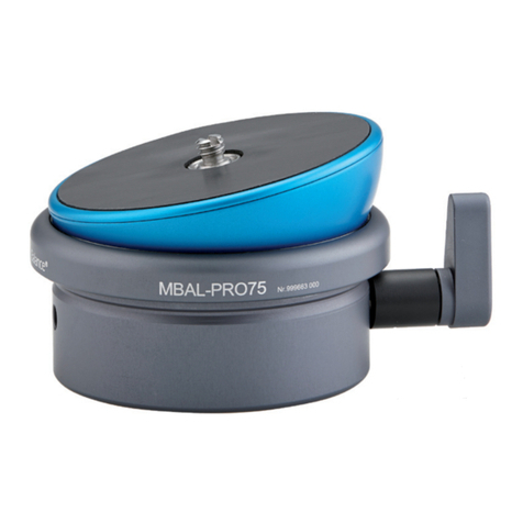
half bowl adapter TRIO B-PRO75, the leveling base MBAL-PRO75
or the geared center column TRIO CC-PRO75.
The 75mm half bowl adapter supports a video head with a compatible
75mm half-ball, the leveling base allows a particularly fast alignment
of a video- or panoramic head and the geared center column enables
quick and precise shooting-height adjustment. See the Handling sec-
tion on page 7-9 of this manual for details.
Handling
Tripod Legs: assembly and disassembly
In order to exchange or replace a leg, screw it out clock-
wise for disconnection, respectively screw it in counter-
clockwise for connection.
Adjusting the leg length
Hold the particular tripod leg in your right hand where the
neoprene leg wraps cover the leg, while you are operating
the twist lock with your left hand. This prevents from unin-
tentionally unscrewing the leg from the basis.
Page 9
Stud Screw or thread hole exchange: 3/8“ for 1/4“
For changing the upper stud screw thread, remove the screw (7) using a screwdriver (in-
cluded Multi-Tool), turn the screw upside down. On one side the screw has a 3/8”-, on the
other side a 1/4” thread.
The 3/8” thread hole at the bottom of the MBAL’s housing is equipped with an 1/4” reducer
bushing, which can be removed if needed.
Installing the geared center column TRIO CC-PRO75
After removing the upper tripod platform, bring the crank (9) in a position near the column,
so that it fits through the tripod basis mouth. Now insert the column from above into the
70 mm tripod basis mouth.
In order to fully operate the crank (9), turn the
column in a position, so that the crank is standing
right in the middle of two tripod legs.
When the white plastic ring is just before the tri-
pod basis mouth, you have to put a little pressure
from above on the column, because the inner snap
ring has to be overcome.
At the end, tighten the three headless screws (5)
at the tripod basis again.
Using the geared center column
In the columns upper part there is the fixing ring
(8), which is used to lock the current position by
hand. Before adjusting the height, this ring has to
be loosened. After that, you can set up the height
precisely with the crank (9). With the help of the
columns self-locking helical gearing, the camera
won’t move down. Nevertheless lock the current
position after adjusting the height with the fixing
ring (8) for maximum stability.
Stud screw exchange: 3/8“ for 1/4“
The column is equipped with 3/8“ stud crews (10)
on both sides for mounting a tripod head. In order
to switch to the smaller 1/4“ thread, dismount the
screw, turn it upside down and mount it in again.
On one side the screw has a 3/8”-, on the other
side a 1/4” thread. For this, the inner nut has to be
opened and tightened with a ring wrench.
9
8
10
10
TRIO CC-PRO75
Page 5
Turn the twist lock at about 90° clock-
wise and slide the leg out until you have
reached the desired length. Afterwards
tighten the twist lock again counter-
clockwise.
Tip: When tightening, always begin with
the biggest leg segment. When loosen
a segment begin with the smallest one.
Tip: When setting up the tripod you
can open all twist locks simultane-
ously, grabbing all locks together with
your hand. Then turn all twist locks at
about 90°.
Adjusting the leg angles
The angle stops can be unlocked by pressing the blue buttons. At first, set up a relatively
large angle while pressing the blue button (larger than wanted). Now, keep your finger o
the button and swing the leg down. It will snap in with a loud click at the angle positions
180°, 155°, 87°, 65°, 45°
or 23°. When you have
found the wanted posi-
tion, move the leg a short
way back until this move-
ment will be blocked by
the internal end stop.
This is the most stable
position.
Page 8
Installation of the 75mm half bowl
adapter TRIO B-PRO75
After disassembling the adapter plate,
insert the adapter from the top into the
70mm opening of the tripod base and
tighten the three headless screws (5) on
the tripod base.
The half bowl adapter can now accom-
modate compatible tripod heads with
attached 75mm half-ball sockets.
5
5
5
Installing the levelling ball MBAL-PRO75
First unscrew the fixing lever (4) completely out of
the housing.
Remove the distance shell (3, illustration page 7).
This part is only needed when the levelling ball is
used independently from the TrioPod PRO75.
Now insert the levelling ball from above into the
70 mm tripod basis mouth. For this bring the white
marking dot on the MBAL’s housing in line with the
white marking line on the basis (6). The hole for the
fixing lever is located straight below.
After that screw the fixing lever from outside through
the basis hole into the levelling ball (without distance
shell) until it can no longer be turned.
At the end, tighten the three headless screws (5) at
the tripod basis again.
4
Using the levelling ball
In order to level a mounted
device with the horizon,
loosen the fixing lever (4)
and level the device with
the help of a spirit level.
After that tighten the fixing
lever again.
All Novoflex panorama
plates have corresponding
spirit levels for judging ac-
curate levelling.
45
5
5
6
7
Page 6
Replacing the rubber feet by steel spikes
Rubber feet should be used when working on a hard
ground like wooden- or stone floor. This reduces vibra-
tions. In contrast to spikes, which perform very well on soft
grounds like a meadow or sandy floor. To change, turn the
rubber feet counterclockwise out of the leg and screw-in
the spikes clockwise.
Advice: When mounting make sure that the foot/spike is
well fixed, so that it can not dismount unintentionally. Each
steel spike can be tightened using a wrench and has a hole
for plugging in a lever.
Setting up the leg movement
The force, which is needed to adjust the leg angles can be
set up with a hex key at the tripod shoulder hinge (2). The
key is part of the included Multi-Tool. 2
How to assemble / disassemble a tripod head
In order to connect a tripod head, for example the
Novoflex Classic Ball 5 II, place it centered upon
the upper tripod platform and fix it from below
with the 3/8“ screw. For this, use the hex key which
is part of the Multi-Tool (included in the scope of
delivery). To secure the tripod head against twist-
ing, it can be fixed in addition with the help of two
small headless screws from below. The fitting hex
key is part of the Multi-Tool.
Advice: For disassembly do not turn the tripod
head, but loosen all screws from below only. This
prevents ugly scratches at the surface of the plat-
form.
9
TRIO CC-PRO75
Page 7
The 75mm half bowl adapter (TRIO B-
PRO75, optional accessory) fits into the
upper accessory mount of the TrioPod
PRO75 tripod shoulder. It accepts com-
patible tripod heads with attached 75mm
level half-ball sockets.
The levelling ball MBAL-PRO75, (op-
tional accessory) was specifically de-
signed for the TrioPod PRO75. This base
is suitable very well for tasks, when only a
little alignment is needed and this adjust-
ment should be done quick and simple.
For example when a video head, a tele-
photo gimbal head or a panoramic head
should be levelled.
Installing the half bowl adapter TRIO B-PRO75, the levelling ball MBAL-PRO75
or the geared center column TRIO CC-PRO75
The geared center column TRIO CC-PRO75, (optional accessory) is
suitable for quick and precise shooting-height adjustment. A time-con-
suming leg length matching is no longer required.
All devices can be inserted into the 70 mm tripod basis mouth and fixed
using three headless screws.
Removing the upper tri-
pod platform
For this, loosen the three
headless screws (5) at about
2/3 of theirs length. Use the
hex key which is part of the
Multi-Tool (included in the
scope of delivery).
After that, pull out the tripod
platform.
5
55
MBAL-PRO75
4
3
TRIO B-PRO75

This manual suits for next models

1

Other NOVOFLEX Camera Accessories manuals

NOVOFLEX Q-BASE II User manual

NOVOFLEX

NOVOFLEX Q-BASE II User manual

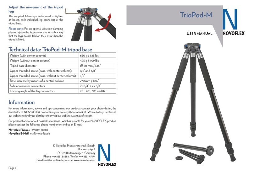
NOVOFLEX TrioPod-M User manual

NOVOFLEX

NOVOFLEX TrioPod-M User manual

NOVOFLEX MiniConnect MR User manual

NOVOFLEX

NOVOFLEX MiniConnect MR User manual

NOVOFLEX VR-SYSTEM SLIM User manual

NOVOFLEX

NOVOFLEX VR-SYSTEM SLIM User manual

NOVOFLEX BAL-NIKZ User manual

NOVOFLEX

NOVOFLEX BAL-NIKZ User manual

NOVOFLEX Panorama VR-System Mini User manual

NOVOFLEX

NOVOFLEX Panorama VR-System Mini User manual

NOVOFLEX MagicBalance PRO75 User manual

NOVOFLEX

NOVOFLEX MagicBalance PRO75 User manual

NOVOFLEX VR-System PRO II User manual

NOVOFLEX

NOVOFLEX VR-System PRO II User manual

NOVOFLEX MICROPOD User manual

NOVOFLEX

NOVOFLEX MICROPOD User manual

NOVOFLEX MFT-RETRO User manual

NOVOFLEX

NOVOFLEX MFT-RETRO User manual

NOVOFLEX CASTEL Mini II User manual

NOVOFLEX

NOVOFLEX CASTEL Mini II User manual

NOVOFLEX CASTEL-XQ II User manual

NOVOFLEX

NOVOFLEX CASTEL-XQ II User manual

NOVOFLEX MagicBall FREE User manual

NOVOFLEX

NOVOFLEX MagicBall FREE User manual

NOVOFLEX MiniConnect MC User manual

NOVOFLEX

NOVOFLEX MiniConnect MC User manual

NOVOFLEX MagicBall MB MINI User manual

NOVOFLEX

NOVOFLEX MagicBall MB MINI User manual

NOVOFLEX VR-System III User manual

NOVOFLEX

NOVOFLEX VR-System III User manual

NOVOFLEX FALCON User manual

NOVOFLEX

NOVOFLEX FALCON User manual

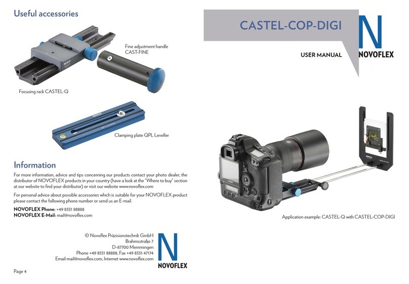
NOVOFLEX CASTEL-COP-DIGI User manual

NOVOFLEX

NOVOFLEX CASTEL-COP-DIGI User manual

NOVOFLEX ClassicBall CB3-II User manual

NOVOFLEX

NOVOFLEX ClassicBall CB3-II User manual

Popular Camera Accessories manuals by other brands

Selectronic SelectCell Ultimate 280 Series instruction manual

Selectronic

Selectronic SelectCell Ultimate 280 Series instruction manual

SwiftCam G3S Startup guide

SwiftCam

SwiftCam G3S Startup guide

Eneo AK-5 Callisto dome series installation guide

Eneo

Eneo AK-5 Callisto dome series installation guide

Gitzo GM2560T parts list

Gitzo

Gitzo GM2560T parts list

Godox XProN user manual

Godox

Godox XProN user manual

Canon BG-R10 instructions

Canon

Canon BG-R10 instructions

Intercel CELL POWER Battery Alert owner's manual

Intercel

Intercel CELL POWER Battery Alert owner's manual

Simu AUTOSUN 2 quick start guide

Simu

Simu AUTOSUN 2 quick start guide

Philips PowerLife LR6PC24C Specifications

Philips

Philips PowerLife LR6PC24C Specifications

CBE Energy Line BDS180 user manual

CBE

CBE Energy Line BDS180 user manual

Sony HDVF-EL100 Operation manual

Sony

Sony HDVF-EL100 Operation manual

Nauticam NA-NEX5R instruction manual

Nauticam

Nauticam NA-NEX5R instruction manual

Nikon DS-L1 instructions

Nikon

Nikon DS-L1 instructions

Magnus Rex VT-5000 owner's manual

Magnus

Magnus Rex VT-5000 owner's manual

Topcon BG-5 instruction manual

Topcon

Topcon BG-5 instruction manual

Fortress Power LFP-5 installation manual

Fortress Power

Fortress Power LFP-5 installation manual

ADEMCO AD8GC18W Brochure & specs

ADEMCO

ADEMCO AD8GC18W Brochure & specs

DigiPin 13 PARE user manual

DigiPin 13

DigiPin 13 PARE user manual

manuals.online logo
manuals.online logoBrands
  • About & Mission
  • Contact us
  • Privacy Policy
  • Terms and Conditions

Copyright 2025 Manuals.Online. All Rights Reserved.