Probewell MT-1/WT1 User manual

MT-1/WT1
User's Guide
Version 2.0 –February 2020
IT IS ESSENTIAL THAT THIS INSTRUCTION BOOK BE READ THOROUGHLY BEFORE
PUTTING THIS PRODUCT INTO SERVICE.
© Copyright 2020 by Probewell Lab Inc. Printed in Canada.
All rights reserved, including those to reproduce this manual or parts thereof, in any form
without the express written permission of Probewell Lab Inc.

Probewell Lab Inc.
Page •2
Limited Warranty
Your MT-1/WT1 comes with a two-year hardware warranty. Probewell Lab Inc.
(Probewell) warrants this MT-1/WT1 against defects in material and workmanship
for a period of two (2) years from the date of purchase from Probewell. This warranty
applies only to the original purchaser of the MT-1/WT1 and is not transferable.
All accessories come with a two-year hardware warranty. Probewell warrants all
accessories against defects in material and workmanship for a period of two (2) years
from the date of purchase from Probewell. This warranty applies only to the original
purchaser and is not transferable.
This warranty does not cover any damage caused neither by negligence, non-
authorized modifications, or parts installed without prior written permission from
Probewell.
This warranty does not apply if the product has been damaged by accident, abuse,
misuse, or misapplication, nor as a result of service to the product by anyone other
than Probewell.
PROBEWELL IS NOT RESPONSIBLE FOR ANY LOST PROFITS, LOST SAVINGS OR OTHER
INCIDENTAL OR CONSEQUENTIAL DAMAGES ARISING OUT OF THE USE, OR INABILITY
TO USE, OF THIS PRODUCT. THIS INCLUDES DAMAGE TO PROPERTY AND DAMAGES
FOR PERSONAL INJURY. THIS WARRANTY IS IN LIEU OF ALL OTHER WARRANTIES
INCLUDING IMPLIED WARRANTIES OF MERCHANTABILITY AND FITNESS FOR A
PARTICULAR PURPOSE.
Disclaimer
Probewell Lab Inc., (Probewell) reserves the right to make changes to this document
and the products which it describes without notice. Probewell shall not be liable for
technical or editorial errors or omissions made herein; nor for incidental or
consequential damages resulting from the furnishing, performance, or use of this
material.
Features and specifications are subject to change without notice.

MT-1/WT1 User’s Guide
Page • 3
Table of contents
Introduction............................................................................................................... 7
MT-1/WT1 Overview ............................................................................................. 7
Front/Rear View of the Socket .......................................................................... 8
Side View of the Socket ..................................................................................... 9
Functioning Theory.............................................................................................. 11
Meter Testing .................................................................................................. 13
Accessories .......................................................................................................... 15
Metercam ........................................................................................................ 15
Optical Pickup.................................................................................................. 16
Meter Adapters ............................................................................................... 17
Operations............................................................................................................... 19
Summary.............................................................................................................. 20
Installation of the Socket..................................................................................... 21
Connecting to the MT-1/WT1.............................................................................. 23
Running the application....................................................................................... 23
Tests available ..................................................................................................... 24
Test Examples...................................................................................................... 25
Example 1: Quick test - Solid-state 2S meter................................................... 26
Example 2: Custom Test - Solid-state 12S meter............................................. 28
Example 3: Tracking Test - 12S(N) meter......................................................... 29
Example 4: Custom Test - 2S electromechanical meter................................... 31
Example 5: Meter tested in the meter shop.................................................... 33
Specifications........................................................................................................... 35
Compatible Meter Forms......................................................................................... 39
Form 1S................................................................................................................ 40
Form 2S................................................................................................................ 41
Form 3S................................................................................................................ 42
Form 4S................................................................................................................ 43
Form 5S(N) (N 2CT) ............................................................................................. 44
Form 5S (3 2CT)................................................................................................. 45
Form 5S(3 2CT 2VT) .......................................................................................... 46
Form 5S(4 2CT ) ................................................................................................ 47
Form 5S(4Y 3CT).................................................................................................. 48
Form 5S(4Y 3CT).................................................................................................. 49
Form 5S(4Y 3CT 2VT)........................................................................................... 50
Form 12S (25S) (3N)............................................................................................. 51
Form 12S (25S) (3)............................................................................................. 52
Form 35S (3)...................................................................................................... 53
Form 45S (4 C) .............................................................................................. 54
Form 45S (4Y 2CT 2VT) ........................................................................................ 55
Form Configurations................................................................................................ 57
Troubleshooting ...................................................................................................... 59

Probewell Lab Inc.
Page •4
Parameters for Data Logging Option....................................................................... 61
Customer Service..................................................................................................... 63
Recommendations................................................................................................... 65

MT-1/WT1 User’s Guide
Page • 5
Liste of abreviations
Abbreviation
Complete Term
A
Ampere
Amp
Ampere
AC
Alternating Current
AP
Access Point
ATK
Accuracy Testing Kit
CFM
Cubic feet per minute
CL
Class
CSV
Comma Separated Value
CT
Current Transformer
DSP
Digital Signal Processor
HL
High Load (Full Load)
Kh
Watthour constant. The number of watthours represented by
one revolution of the disk. Also, called disk constant.
Kt
Test constant. For electronic (no disk) meter, the amount of
energy represented by each calibrated pulse of the LED.
kW
Kilowatt
Lb
Pound
LL
Light Load
NIST
National Institute of Standard and Technology
PF
Power Factor
PPI
Pore per inch
Rev
Revolution, number of revolutions
RMS
Root mean square
TA
Test Ampere
THD
Total Harmonic Distortion
V
Volt
VA
Volt-Ampere
VAC
Volt Alternating Current
VARh
VARhour (Volt Ampere Reactive Hour)
Vdc
Voltage direct current
VT
Voltage Transformer
W
Watt(s)

Probewell Lab Inc.
Page •6
Abbreviation
Complete Term
Wh
Watthour
WiFi
Wireless Fidelity
WLAN
Wireless Local Area Network
WWW
World Wide Web
µWh
Micro-Watthour
µVARh
Micro-VARhour

MT-1/WT1 User’s Guide
Page • 7
Chapter 1
Introduction
The Probewell Lab MT-1/WT1 is a portable single-phase meter tester with built-in
WiFi technology.
MT-1/WT1 Overview
The MT-1/WT1 test socket adapter weighs only 6.4 lb which makes it the ideal tool
for field testing. Within a few minutes, a residential, commercial or industrial
electricity meter can be accurately tested on site by meter shop technicians.
The MT-1/WT1 can be set to test single phase meter in one step (Quick Test) or set
to do the two phases simultaneously followed by each element separately (Full Test).
The MT-1/WT1 provides measurements for active and reactive energy with forward
and reverse flow testing capability.
The MT-1/WT1 has a built-in two-phase phantom load made of synthesized 50A
current sources and a two-phase electronic standard with a typical accuracy of
±0.02% and a guaranteed accuracy of ±0.05%. It comes with a complete calibration
report certifying measurement accuracy across its entire operating range.
The MT-1/WT1 comes with a shock resistant carrying bag. The bag has individual
compartments for the test socket, the pickups and the User's Guide. There is also
enough space for small accessories such as the magnetic adapter for the optical
pickup, seals, pliers, etc.
Optional: A handheld remote is available for the MT-1/WT1, having a keypad and an
LCD display and weighing only 0.6 lb.
Probewell Lab Inc.
Page •8
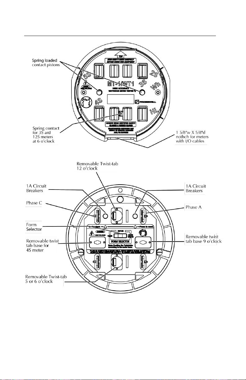
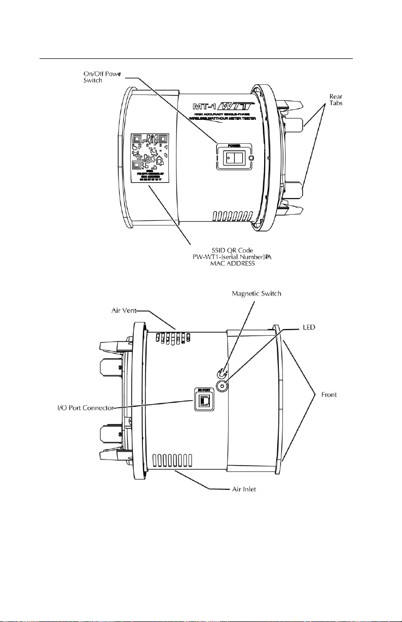
Front/Rear View of the Socket
Fig. 2.1 –Front and Rear View of the Socket
Fig. 2.1 shows the removable twist-tabs which do not require any tools to be moved
from a position to another. The above illustration shows only the twist-tab
positioned at 6 and 12 o’clock.
MT-1/WT1 User’s Guide
Page • 9
Side View of the Socket
Fig. 2.2 –Side View of the Socket

Probewell Lab Inc.
Page •10
Identification
Description
Rear Tabs
The rear tabs connect the socket to the front jaws of the
meter base. The socket gets its power directly from the
meter base (100-600VAC) circuit. The service current
shorting bars (bypasses) are rated for high capacity
amperage.
Removable Tabs
These tabs can be positioned at 3, 5, 6, 9 or 12 o'clock
position as required by the meter base where the test is
conducted. See Appendix C.
Form Selector
In position 1S, 2S, the unit is powered from the two
upper tabs. In position 3S, 12S, the unit is powered from
the Phase C and the neutral tab. In position 4S, 5S, 35S
and 45S the unit is powered from the 3 and 9 o'clock tabs
for the 4S or the unit is powered from the 5 and 12
o'clock tabs for the 5S, 35S and 45S.
Circuit Breakers
Protection for the MT-1/WT1 and the meter. Two circuit
1A breakers which can be reset by pressing a spring-
loaded button.
Power Switch
Socket's main power on/off switch.
Front Jaws
The front jaws are controlled by internal relays allowing
to test meters. The front jaws become live only when a
meter is inserted. The voltage on the front jaws is
current-limited for additional protection.
Pistons
These are actuated by the small lugs on the back of the
meter when inserted for testing.
I/O Connector
Isolated full-duplex communication port. It also provides
an isolated and current limited low voltage supply for the
accessories (optical pickup and metercam) and the
optional handheld remote control.
QR Code Sticker
The QR code sticker contains the access point
information to be scanned for a mobile device as well as
the MAC address.
LED
Socket Status Indicator.
Magnetic Switch
Switch for any manual entry using a magnet.
Air Vent(1)
Warm air exit. A 5 CFM miniature fan forces air
circulation inside the socket.
Air Inlet(1)
Cool air input. Filtered through polyurethane foam filter.
(1) Do not block air circulation. Keep away from direct heat or flame.

MT-1/WT1 User’s Guide
Page • 11
Functioning Theory
MT-1/WT1 applies a load to the meter under test, then measures exactly the
quantity of energy that passes through the meter. After a predetermined number of
disk revolutions, or a minimum time in the case of a solid-state meter, the test will
end, and the application (Probewell Connect) will display the difference between the
meter and the MT-1/WT1's internal electronic standard.
Current Applied to the Meter
The current applied to the meter under test is achieved by three independents built-
in 50A synthesized AC current sources. The current level is adjustable and regulated.
The current sources allow to simulate loads at unity and 0.5 lagging power factor.
They are isolated and form three independent current loads in closed-link
arrangement. This configuration allows to check a meter without the need to open
the potential link of the meter and no wiring setup is necessary.
Voltage Applied to the Meter
The voltage applied to the front jaws is derived from the meter base circuit. For
safety reasons, the voltage is applied to the front jaws only when a meter is inserted.
The voltage is also current limited.
The front jaws of the MT-1/WT1 are controlled by internal relays allowing to test
self-contained and CT rated three-phase and single-phase watthour meter form
configurations without wiring setup.
Built-in Electronic Standard
The built-in electronic standard in the MT-1/WT1 has an exceptional accuracy thanks
to the use of electronic transducers developed by Probewell. These transducers have
an exceptional long-term stability and linearity and are not affected by temperature.
The electronic standard does not contain any potentiometers or other types of screw
adjustment that could become unstable with time. It uses digital technology to
ensure a maximum of reliability over time. A DSP processor measures and calculates
the exact energy, active or reactive, that passes through the meter. This technology
has the advantage of obtaining a more compact and lightweight electronic standard
while minimizing electronic components.
Accuracy Test
The MT-1/WT1's electronic standard is calibrated using a primary standard traceable
to NIST and comes with a complete calibration report certifying measurement
accuracy on both Wh and VARh scales over its entire operating range. Accuracy test
on MT-1/WT1 can be done in your own laboratory using:

Probewell Lab Inc.
Page •12
•An electronic reference standard traceable to NIST. The electronic
standard must have at least 1 isolated current input port of a minimum
capacity of 50A with autoranging capability and a typical precision of
0.01% or better;
•A laboratory stabilized and isolated AC power source with fundamental
waveform selectable 120V or 240V, 60Hz, rated at least 150VA;
•The Accuracy Testing Kit (ATK-4) for single phase testers.
For more information on socket accuracy test please refer to the ATK and Probewell
Connect for WT series documentations.

MT-1/WT1 User’s Guide
Page • 13
Meter Testing
Tests performed with a pickup (Optical or Metercam)
Three different tests can be done with optical pickups: Quick, Full and Custom test.
Quick Test or Full Test are made up of a predetermined sequence of consecutive
steps and tests, all of which are done in one operation. The sequence is
programmable and can be modified through the Settings tab. By default, the
sequence includes one test point with each of the loads: HL, PF and LL.
In Quick Test, the two phases (A+C) are tested simultaneously in one step.
In Full Test, a Quick test is performed followed by each phase separately (A and C).
In the Settings tab, there is an option to remove the PF and/or LL for each single
element test.
Please note that with single-phase meters, only the Quick Test will be activated as
there is no Full Test for single-phase meters.
Custom consists in choosing one of the three loads to apply to the meter: HL, PF or
LL. The disk revolutions or pulses are counted automatically by the pickup. No critical
timing is required to start a test. The test ends automatically.
When testing a polyphase meter, you can also choose to apply the load on all phases
(A+C) at the same time or on each phase individually (A or C). The phase selection is
done by selecting the appropriate phase (A, C, or A+C) in the Select Active Phase drop
down window.
Tests performed without a pickup (Optical or Metercam)
Manual test is used when the operator counts the disk revolutions manually. A
magnet is used to start and end the test manually by applying it to the side of the
socket (see figure 2.2). The operator can set his own parameters for conducting a
test, such as the number of revolutions and the load to be applied. The load can be
switched dynamically during the test.
Please note that without the help of a pickup, if the operator signals the start or the
end of a test too soon or too late using the magnet, the number of disk revolutions
(a whole number without fraction) might not be accurate and will affect the precision
of the test.
Tracking test is like the manual test except the socket counts the number of
revolutions and displays them on your wireless device. The count is based on the
selected Kh of the meter and the cumulative watthours recorded by the MT-1/WT1
and not the physical count of the disk revolutions. A magnet can be used to start and
end the test.

Probewell Lab Inc.
Page •14
kW Demand test allows the operator to do a kW demand test. The kW demand test
is calculated using the following formula:
kW = kWh x 60/T
Where T = Demand interval length in minutes
Note: With solid-state metering, conducting energy and demand tests may be
considered redundant since they are both results of the same measurement.
Set up the meter for a kW demand test following the manufacturer's instructions.
Please note that the kW demand test method varies between manufacturer's
reference technical guide for instructions.
Line monitor Test analyzes the input voltage to determine statistically the line
voltage, frequency fluctuations and its harmonic content (THD) up to the 32nd order.
MT-1/WT1 User’s Guide
Page • 15
Accessories
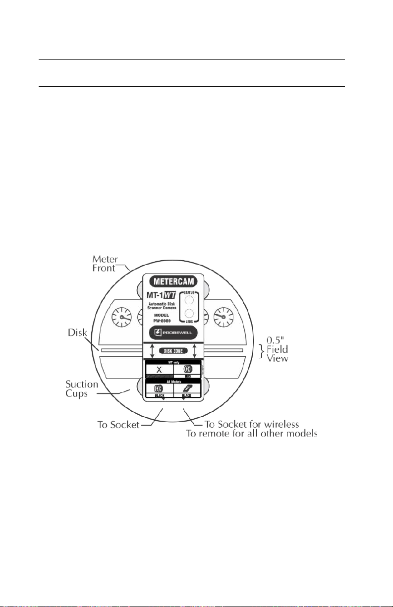
Metercam
The Metercam is used with an electromechanical meter (rotating disk). It is a digital
disk sensor without the many drawbacks found on usual photoelectric sensors, such
as difficulty to align properly and sensitivity to light. With the Metercam, no
alignment is necessary since it detects and picks up the disk by itself. Another feature
is its electronic shutter that makes it insensitive to light variations including bright
sunlight.
The Metercam is built around a miniature digital camera with a ½" field view
combined with a RISC processor that detects the position of the meter disk and locks
automatically on the reference point (black flag).
The Metercam is mounted on four suction cups installed directly on its backside.
For a good and lengthy hold, lightly wet the inside of the suction cups, especially
when field testing in colder weather. Also, keep the inside of the suction cups clean.
Fig. 2.4 –Metercam
Note: for electromechanical meters with a hidden disk, a side-mount Metercam is
available.

Probewell Lab Inc.
Page •16
Optical Pickup
The optical pickup is used with solid-state meters. It is mounted with a suction cup
or integrated in a magnetic head that detects infrared light pulses from solid-state
meters. The optical pickup uses edge triggering for less sensitivity to changes. On the
top of the head of the pickup, there is a pulse indicator in the form of a visible red
led that flashes when pulses are being received.
Fig. 2.5a –Optical Pickup
Fig. 2.5b –Magnetic Optical Pickup
Adapters
The Focus Adapter is used with the
Optical Pickup for meters with a
protuberant shape over the test pulse
The Magnetic Adapter is used to install
the suction cup of Optical Pickup on
meters with a metallic port.

MT-1/WT1 User’s Guide
Page • 17
Meter Adapters
Sensus 3S: This adapter is used to test Sensus’ 3S meter, without this adapter the
meter will be damaged.

Probewell Lab Inc.
Page •18

MT-1/WT1 User’s Guide
Page • 19
Chapter 3
Operations
CAUTION!
The use of MT-1/WT1 is strictly reserved to personnel authorized to manipulate
electric installation meters. For safety reasons, certified safety glasses and rubber
gloves are strongly recommended but are not provided with the MT-1/WT1.
The operation of removing and inserting a meter from its meter base under power
exposes live electric terminals. Be careful. Do no stick your hands or any metal
objects into the open meter base. You could suffer bodily burns, electric shocks
and even electrocution.
It is imperative you follow the safety procedures of your company.

Probewell Lab Inc.
Page •20
Summary
The MT-1/WT1 is compatible with meter Forms 1S, 2S, 3S, 4S, 5S, 12S, 35S and 45S
meters. Before testing a meter in the field, always make sure the electrical wiring of
the meter base is fully compatible with those shown in Appendix B.
The MT-1/WT1 socket must first be inserted between the meter base and the meter.
The installation procedure for a ringless meter base is described hereafter in Fig. 3.1.
When powered on, the MT-1/WT1 recognizes the type of meter installed and
validation of the form and the TA is required. With some meters, it is sometimes
necessary to select the form manually.
When a pickup (Optical or Metercam) is used, the socket detects the Kh of the meter
and uses it. If for some reason the Kh suggested does not match the Kh indicated on
the meter, the operator can change it manually by restarting the socket and disabling
Kh autodetection. Without a pickup, the user must manually enter the meter Kh.
The next step is to choose a type of test to perform.
If a pickup is used, the test becomes fully automatic and the modes available
are Custom, Quick and Full.
Without a pickup, the modes Manual and Tracking are available. In Tracking,
the test is done manually and the meter disk (or the simulated disk in case of
a solid-state meter) must do a precise number of revolutions. It is up to the
operator to start and stop the test precisely using the Start/Stop or the
magnetic switch on the side of the socket.
Once the load is applied and the test has started, the MT-1/WT1 measures the
energy that passes through the meter with its internal electronic standard. All
important measurements are shown on the mobile device or computer display while
testing.
When the test ends, the test result is displayed in percentage error (Ex. -0.02%) or in
percentage registration (Ex. 99.98%).
Table of contents
Other Probewell Test Equipment manuals

Probewell
Probewell ST-3 User manual

Probewell
Probewell ST-3 Instruction Manual

Probewell
Probewell ATK-3 User manual

Probewell
Probewell ST-3 User manual

Probewell
Probewell ST-3 User manual

Probewell
Probewell ST-3/XT3 User manual

Probewell
Probewell MT-1/WT3 User manual

Probewell
Probewell MT-1/WT3 User manual

Probewell
Probewell ST-3/XT3 Instruction manual
Popular Test Equipment manuals by other brands


Dräger
Dräger Alcotest 6510 Instructions for use

Furukawa
Furukawa OFS V-System quick start guide

MAGUIRE
MAGUIRE PRS-20 Installation operation & maintenance

Rigol
Rigol DG2000 Series Performance Verification Guide

PCB Piezotronics
PCB Piezotronics 8159-0051A Installation and operating manual

Snap-On
Snap-On POLARTEK EEAC330 manual


