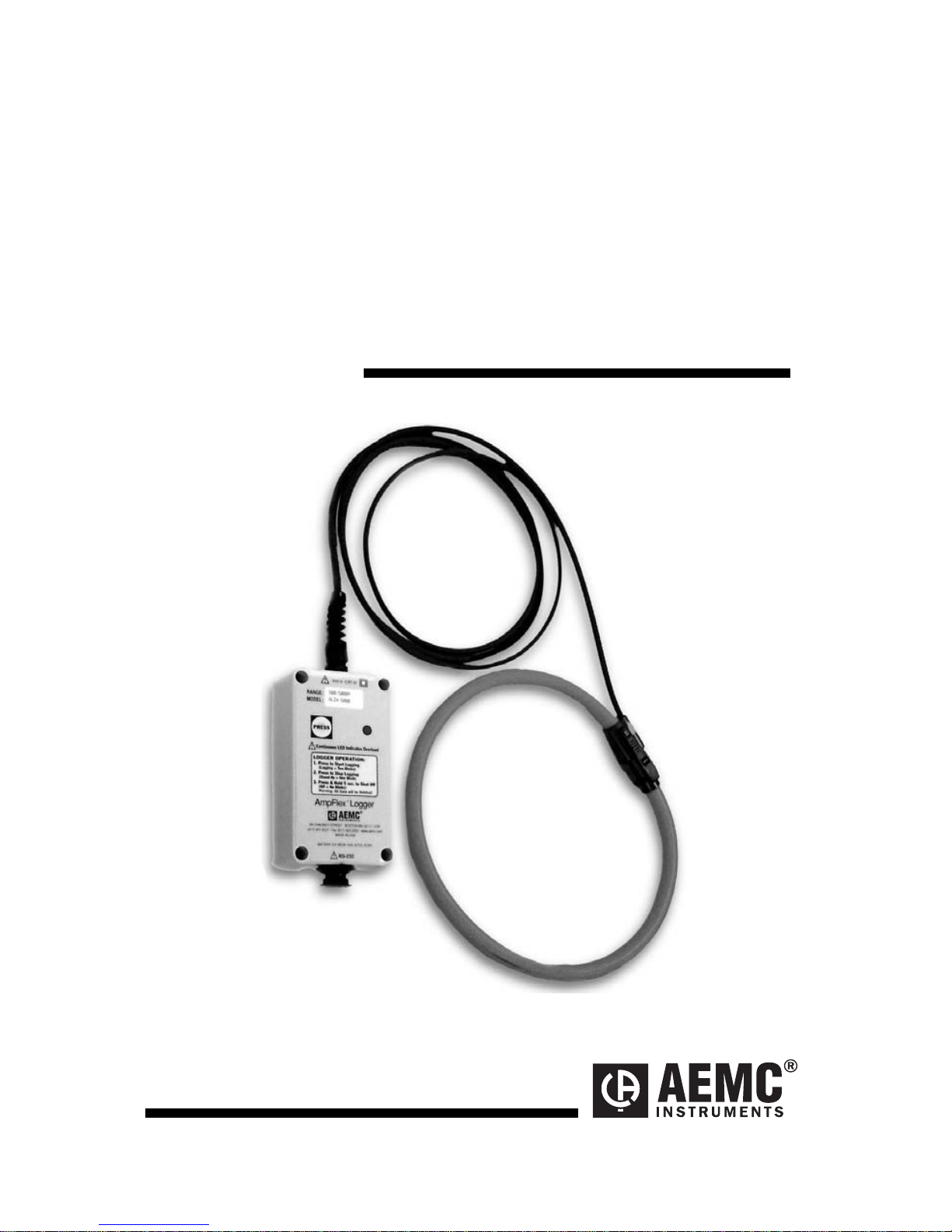
Simple Logger®AmpFlex®Current Probes
7
Battery Installation
Under normal conditions, the battery will last up to 6 months of
continuous recording unless the logger is restarted very frequently.
In the OFF mode, the logger puts almost no load on the battery. Use the
OFF mode when the logger is not in use. Replace the battery every six
months in normal use.
If the logger will be used at temperatures below 32°F (0°C) or is
frequently turned on and off, replace the battery every three to four
months.
1. Make sure your logger is turned off (no light blinking) and all
inputs are disconnected.
2. Turn the logger upside down. Remove the four Phillips head
screws from the base plate, then take off the base plate.
3. Locate the two-wire (red/black) battery connector and attach the
9V battery to it. Make sure that you observe polarity by lining up
the battery posts to the proper terminals on the connector.
4. Once the connector is plugged onto the battery, insert the battery
into the holding clip on the circuit board.
5. If the unit is not in record mode after installing the new battery,
disconnect it and press the button twice then reinstall the battery.
6. Reattach the base plate using the four screws removed in step
two.
Your logger is now recording (LED blinking). Press the test button for 5
seconds to stop the instrument.
Note: For long-term storage, remove the battery to prevent discharge
effects.
Operation
Position the AmpFlex®sensor around the conductor to be measured. Be
sure that the positioning of the logger sensor does not violate the
minimum allowable bending radius of 0.75 inches (19mm).
Next, press the start/stop button on the front of the unit to begin the
recording session. The indicator light will double blink to indicate that the
recording session has started. When the recording session has been
completed, press the start/stop button to end the recording. The indicator
light will single blink to indicate that the recording session has ended and
the unit is in stand-by. Remove the logger from the conductor and
transport it to the computer for data downloading. See the User Guide for
downloading instructions.