NOYAFA NF-388 User manual

INSTRUCTION MANUAL INSTRUCTION MANUAL INSTRUCTION MANUAL INSTRUCTION MANUAL INSTRUCTION MANUAL INSTRUCTION MANUAL
NF-308/NF-388
ORIGINAL
AUTHENTIC
e
d
p
r
o
d
u
n
t
c
t
e
t
s
a
,
P
i
ng
n
o
t
e
i
t
a
r
f
l
t
e
l
o
n
w
u
e
o
d
C
ORIGINAL
AUTHENTIC
Your excellent helper in cable test!
Wire Fault Locator
Your excellent helper in cable test! NF-308
NF-388
VER: V1

Please read and learn safety instructions
before use or maintain the equipment
humidity and high tempera ture ( over 4 0 ).
it may resul t in damage to equipmen t.
ance and care shall be conduc ted by p rofessional perso nnel .
The tester will shut off automatically if it does no t work for
30 mi nute s in succession.
equipment is not used for a long time s o as to pr event that the
battery li quid is leaked in futur e.
(such as power supply circuit of 22 0V), o ther wise, it may result
in damage to equipment and pe rson al injury.
thunderstorm weather so as to pre vent l ightning stroke and
impact on personal safety.
Your excellent helper in cable test!
Contents
Your excellent helper in cable test!
Overview ...........................................................01
Main Functions and features .............................02
Technical index .................................................02
Product interface and keypad Introduction ........04
Product operation methods ...............................05
Start up or shut down AF hunting function .........11
Diagram of series products ............................12

Main tester(NF-308) Receiver Remote identifier
NF -30 8
1.Wiremap
2.Wair&Length
3.Coax/Tel
4.Polar Test
PUSH TO TEST
POWER
NF -30 8-S
VOL
PAIR&L
SCA N
OFF
WIREMAP
NF -30 8-R
Wire F au lt Loca tor
RE C EI V E R
Wire F aul t Locat or
EM I T T ER
STAT US
NF-308 is a practical cable test & inspection instrument with lots
of new functions researched and developed by our company, which
is composed of tester (NF-308), receiver (NF-308-S) and remote
identifier. It owns three great functions of wire hunting,wire sorting
and circuit status testing quickly and accurately. thus, it becomes
available tool for technicians in installation and maintenance of
weak current system, such as, communication line, comprehensive
wiring circuit, etc. It is widely applicable to telephone system,
computer network and other fields.
Overview
Your excellent helper in cable test!
01
Main Functions and features
One person enough to complete cable continuity check.
Directly hunt 5E, 6E, telephone wire, coaxial cable, USB cable
and other cables.
Check wiring error in 5E, 6E, coaxial cable, such as open circuit,
short circuit, jumper wire, reverse connection .
Locate the wiring or connection error.
Measure cable length and determine the distance of open
circuit and short circuit for Lan cable.
Dynamically calibrate cable length and make length measurement ●
as accurate as 98%.
Simple and easy use. Big screen to display test result clear.
Portable unit with long battery life (wait-case 50 hours).
Automatically time-delay shut off and backlight display function.
Measure length and pair with or without far-end recognizer.
Far-end recognizer with prompt voice.
Self-checking function and automatically compensate any change
in battery capacity or ambient temperature.
Single board computer software watchdog design and reliable
operation.
Technical indexes
(1). Overall dimension
Main tester: 185×105×50mm; receiver: 218×46×29mm;
Remote identifier: 84×34×27mm.
(2). Power
Two laminated batteries of 9V.
(3). Display
Big LCD screen: Special 4 x 16 character
(valid visual field 61.6 x 25.2 mm).
(4). Type of cable tested
STP/UTP twin twisted cable, coaxial cable.
Your excellent helper in cable test! 02
5.Setup

(5). Type of cable detected
5E, 6E, telephone wire, coaxial cable, USB cable and
other metal wires.
(6). Ambient temperature in work
-10 ~+60
(7). Tester Port
Tester RJ45 master port (M), tester LOOPBACK RJ45 port (L),
RJ45 Scan( RJ45 cable tracing);
Remote identifier RJ45 port (R)
The extra BNC and RJ11 converters are used to measure and
check the continuity of coaxial cable and telephone line.
(8). Length Measurement of Twin Twisted Cable
Scope: 1~1000 M ( 3 ~3200 ft)
Calibration accuracy: 3% (+/- 0.5M or +/- 1.5 ft)(calibrating
cable > 10 M)
Shipment accuracy: 5% (+/- 0.5 M or +/- 1.5 ft).(AMP, AT&T
Class 5 cable)
Display: M or ft.
(9). Length Calibration:
User can set calibration coefficients by himself with a given
length cable.
The length of calibrating cable is more than 10 M.
(10). Wire Sequence and Locating Cable Error:
Check errors such as open circuit, short circuit, reverse
connection, cross-over.
(11). Automatic Time-delay Shut Off Time:
The tester will shut off automatically after 30-minute
non-operation.
Your excellent helper in cable test!
03
Product interface and keypad Introduction
Main tester
Receiver Remote identifier
NF -3 0 8
POWE R
SCAN
RJ11
SCAN
USB
SCAN
POWER
RJ45
LOOPBACK
MAIN SCAN
WIRE MAP BNC
PAIR &L
SCA N
OFF
Wire Fau lt L oc ato r
EM I TT E R
STAT US
PUSH TO TES T
NF -3 08 - S
VOL
Wir e Fa ul t Lo ca to r
RE CE I VE R
WIREMAP
NF -3 0 8- R
Your excellent helper in cable test! 04
1.Wiremap
2.Wair&Length
3.Coax/Tel
4.Polar Test
5.Setup

N e tW o rk S TE S T
v e r6 . 8
nf-3 0 8
Product operation methods
Carry out self-checking at the same time (The dotted line dynamically
displays the course of self-checking from left to right):
Wait 5 seconds or push any arbitrary key to display main menu.
Main menu display:
Wiring diagram (WIREMAP) test function:
After entering the wiring diagram (WIREMAP), the tester shall
carry out wiring diagram (WIREMAP) test and displays as follows
----T e s t i n g ----
There are four functions to be chosen on main menu.
1. WireMap --- Wiring diagram measurement to check end-to-end
continuity of cables in M, L, R and locate errors.
2. Pair & Length ---Pair and measure length to know open,short,points,
verify cable length,open circuit distance.
3. Coax/Tel --- Coaxial cable and telephone line .
4. SETUP---Calibrate and set up the tester (Refer to description
hereinafter).
Note:never put a telephone cable into RJ45 Port especially a
charged one,for fear of burnout to the tester.
12345678
Your excellent helper in cable test!
05
Test Result 1: Short circuit (SHORT)
It displays as follows if there is any short circuit in cable or terminal:
(e.g.12 short circuit in the sample)
S h o r t :
1 2
At the moment, push key to restart testing or push key to return
main menu.Always eliminate “short”error firstly and then start further
measurement.
Test Result 2:It will display as follows if the cable to be checked does
not insert into the far-end matcher (ID) or the cable does no insert into
the local port
N o a da p te r:
At the moment, push key to restart testing or push key toreturn
main menu.
Test Result 3: Normal wiring diagram (WIREMAP) display
The tester will automatically detect remote unit (ID) or local port (L)cable
and it will display wiring diagram (WIREMAP) as follows if it finds the
remote unit (ID) or cable to be checked in the local port(L):
W i re m a p: pa s s
M: 12345678 id1
Iiiiiiii
R: 12345678
"R" means “Remote tester” , "ID1"is the number of Remote identifier .
"|" is the connecting line between “R” and “M”.
"M:" means “Main tester”.
At the moment, push key to restart testing or push key to return
main menu.
PAIR&L
PAIR&L
PAIR&L
Your excellent helper in cable test! 06
1.Wiremap
2.Wair&Length
3.Coax/Tel
4.Polar Test 5.Setup
2.Wair&Length
3.Coax/Tel
4.Polar Test

Test Result 4: Wiring diagram (WIREMAP) display
when there is an open circuit at the far-end of cable.
W i re m a p: fa i l
M: 12345678
Iiiiiiii
R: 12 x45 x78 id1
"R:" line "3" and "6" pins location display "x", it indicates an open circuit
in far-end plug "3" and "6" pins and the open circuit is located nearby the
far-end plug.(The open point should be at the 10% cable length)
because
error at the far-end always displays in pair as above.,which means there
is one open circuit or both are open in the far-end"3"and "6"pins.
Test Result 5: Wiring diagram (WIREMAP) display when
there is an open circuit at the near-end of cable.
It will display wiring diagram (WIREMAP) as follows if there is an open
circuit at the near-end plug of the cable:
W i re m a p: fa i l
M : 1 2 x4 5 67 8
I i ii ii i i
R : 1 23 4 56 78 i d 1
"M:" line "3" pin location displays "x", it indicates an open circuit at
near-end plug "3" pin and the open circuit is located nearby the near-
end plug.(The open circuit should be located within 10% cable length
if it is measured from the near-end plug)
Test Result 6: Wiring diagram (WIREMAP) display when
there is an open circuit in the middle of the cable.
It will display wiring diagram (WIREMAP) as follows if there is an
open circuit in the middle of the cable:
W i re m a p: fa i l
M : 1 23 4 56 78
Iixiiiii
R : 1 23 4 56 78 i d 1
"|" line "3" pin location displays "x", it indicates an open circuit in the
middle of "3" pin cable. (The open circuit should be located within
10%-90%cable length if it is measured from the near-end plug.) as
detailed hereinafter.
Your excellent helper in cable test!
07
Pair and length measurement (PAIR & LENGTH) function:
When testing cable length, just connect one end of cable with
Main tester, no need of remote unit.
After entering into “PAIR & LENGTH” function, it will display as follows to
indicate the measurement is being undertaken:
----T e s t i n g ----
1 2 34 5 67 8. . .
Note:In view of different technical parameters in various brand cables,
the user should calibrate the cable length before length measurement
(Refer to the details herein).
Test Result 1: Short circuit (SHORT)
It will display as follows if there is any short circuit in cable or terminal:
(12 short circuit in the sample)
S h o r t :
1 2
Test Result 2:
Normal pair and length (PAIR &LENGTH) display
P a i r 1 2 1 00 . 0m
P a i r 7 8 9 9. 8 m
P a i r 3 6 1 00 . 3m
P a i r 4 5 1 00 . 2m
return the main menu.
It will display as follows if pair and length(PAIR & LENGTH)
measurement is in normal condition:
PAIR&L
Your excellent helper in cable test! 08

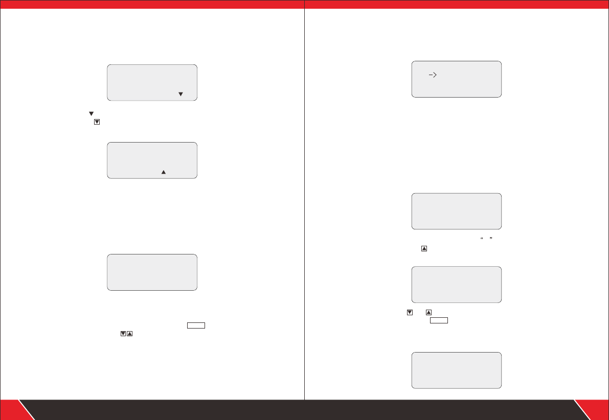
Test Result 3: Abnormal pair and length (PAIR &LENGTH) display
It will display the paired lines and its length firstly,then unpaired lines
display, as shown below.
P a i r 1 2 1 00 . 0m
7 8
P a i r 3 6 1 00 . 3m
P a i r 4 5 1 00 . 2m
The last line (78 ) indicates no pair is found in line 7and 8, at the
moment,push the key, it will display the length of unpaired line
number(as shown below)
It will display " X " to indicate an open circuit if the length is less
than 90% of other lines' length. That is to say, the open circuit is
located at around 89.3M in line 8
P i n 7 1 0 0. 0 m
P i n 8 8 9 .3 m x
Coaxial cable and telephone line measurement function:
After entering into coaxial cable and telephone line measurement
(Coax/Tel)function, the tester shall start to test and show the test
result as follows:
C o ax / te l te s t
P a s s
It shall display“OPEN”if there is any open circuit or the coaxial
cable and telephone line is not connected.It shall display “SHORT”
if there is any short circuit.At the moment,push key to repeat
the measurement or push key to return the main menu . The
far-end recognizer will have “beep” if the connection is in normal
condition.
Note: For coaxial cable measurement, it needs BNC adapter cable.
For telephone line measurement,it needs RJ11 adapter.
PAIR&L
Your excellent helper in cable test!
09
Calibration and setup (SETUP) function:
After entering into calibration and setup (SETUP) function, the tester
shall display as follows:
----s e t u p ----
Unit:meter
C a li b ra ti o n
Q u it
UNIT: It is used to set up length unit and shifts between meter (Meter)
and feet (FT).
CALIBRATION is calibration function.(Detailed as related chapters
hereinafter)
QUIT is used to return the main menu.
Dynamic calibration (CALIBRATION) function:
For an accurate measurement of cable length,the calibration operation
should be done as follows.
After entering into dynamic calibration function, the tester shall display
as follows:
C A L I B R A T I O N ?
N O Y ES
Insert same type cable of given length into M port, do not need insert
far-end recognizer, push key (Yes) to undertake measurement and
display the measured length (as shown below):
P i ea s e ad ju s t?
2 0 .0 m
- o k +
At the moment, hold and key (-/+) to adjust the length to actual
given length and then push key to reserve calibration factor
and exit calibration function.It will display as follows if the cable
length being measured is too short(<10M) to remind the user to
change a longer cable for calibration:
C a bl e t o sh or t !
c o ht i n nt . ca i
N o y es
PAIR&L
Your excellent helper in cable test! 10

S h o r t
1 2
C o nt i nu e?
N o y es
At the moment, push key (No) to exit calibration function. Push key
(Yes) to repeat the measurement.
cable at factory.
Start up or shut down and hunting function
(1). Press PUSH key,the hunting indicator light (SCAN) flashes,which indicates
that audio frequency transmission of main tester is normal , insert the cable to
be tested into RJ45 SCAN Port . then hold the receiver to trace cable needed
(the usage of receiver is shown in the following). RJ11/BNC/ USB cable is
located when inserted into its corresponding port.
(2).The user can turn volume switch to control the volume.
(3).The floodlight function helps the users operate in dark environment.
(4).Earphone helps avoid external interference in noisy environment.
(5).The test can not measure cable length and wire faults when it is
operated to trace cable.
Usage of the receiver
Install 9V battery ,press “PUSH” key, then approach the cable with probe
and find targeted one among lots of cables. When the probe is near target
wire, the “beep, beep and beep” sound will come out and the signal indicator
light “POWER” will be on. When loudest “beep” and brightest indicator
means that is the required cable.
If there is short circuit in cable, It will display as follows.
Your excellent helper in cable test!
11 Your excellent helper in cable test! 12
NF-708 NF-905
NF-806B
NF-468L NF-820 NF-2100
NF-800 NF-816
NF-868 NF-268 NF-8601
NF-911
CCT V Test er Pro
ADDR LIGHT POEWR
ENTER
RETURN
S-PSTC-PST
0
123
7
FOCUS-
4
FOCUS+
5
IRIS+6
ZOOM+
9
ZOOM-
8
IRIS-
CCTV Test erPro NF-708
R
123456
123456
Polarity test
Firstly, insert into RJ11/SCAN port with the standard alligator clips.
Secondly, choose “polar Test” from the main menu when you have clamped the
battery polarity with the clips.
Thirdly, you can see the result shown on the screen: Voltage of the battery, Red
& Black tells you the polarity. (“+”means anode , “-”means cathode).
ATTENTION: whenever you connect anode or cathode for the red & black clips,
it's doesn't matter for the result.
Other manuals for NF-388
1
This manual suits for next models
1
Table of contents
Other NOYAFA Analytical Instrument manuals