NRG Systems 11708 User manual

All-Weather PVH Kit
NRG SRA System | Kits #11708, 11709, 11710
Authors:
Technical Services

NRG Instructions
SRA System | All-Weather PVH Kit
SRA_All-Weather_PVH_Kit_Instructions
Rev. 5.0
support@nrgsystems.com | Page 2
18 April 2018
TABLE OF CONTENTS
INTRODUCTION ..................................................................................................................... 4
MATERIALS & TOOLS ............................................................................................................. 5
In the Kits ..................................................................................................................... 5
Required Tools.............................................................................................................. 5
Recommended Additional Documentation .................................................................... 5
Precautions................................................................................................................... 6
SECTION 1: ASSEMBLING THE ALL-WEATHER SYSTEM TOWER ................................................ 6
1.1 Construct and Erect the 2.2m Tower ........................................................................ 6
SECTION 2: ASSEMBLING THE PV PANELS & BRACKETS........................................................... 7
2.1 Open and unpack all items. ..................................................................................... 7
2.2 Construct the PV Frame ........................................................................................... 7
2.3 Attach Ventilator Control System (Shelter Box) to Tower. ...................................... 15
2.4 Mount 110S Temperature Sensor .......................................................................... 16

NRG Instructions
SRA System | All-Weather PVH Kit
SRA_All-Weather_PVH_Kit_Instructions
Rev. 5.0
support@nrgsystems.com | Page 3
18 April 2018
2.5 Chain the Deep-Cycle Batteries Together ............................................................... 16
SECTION 3: INSTALLATION OF THE VU01 TO THE SRA TOWER............................................... 17
3.1 Install the SR20 Pyranometer into the VU01 ventilator unit ................................... 17
3.2 Connecting the VU01 & Pyranometer to the SRA Tower & SymphoniePRO............. 19
SECTION 4: WIRING THE ALL-WEATHER SYSTEM .................................................................. 20
4.1 Wiring the Ventilator to the Control System .......................................................... 20
4.2 Wiring the NRG 110S Temperature Sensor to the Control System........................... 22
4.3 Wiring Status Signals from the Control System to the Data Logger ......................... 23
4.4 Wiring the Batteries to the Control System ............................................................ 24
4.5 Wiring the PV Panels to the Control System........................................................... 25
SECTION 5: LOGGER CONFIGURATION FOR STATUS SIGNALS................................................ 26
5.1 Heater Status ........................................................................................................ 26
5.2 Fan Status ............................................................................................................. 26
5.3 Battery Bank Voltage Monitoring........................................................................... 27
5.4 Logger Configuration Summary Table .................................................................... 27
SECTION 6: CONFIGURING THE PLC ...................................................................................... 28
6.1 Set the PLC Date and Time..................................................................................... 28
6.2 Start the PLC Program............................................................................................ 28
6.3 Understanding the NRG Default Control Algorithm (PLC) ....................................... 29
6.4 How to Configure the Controller for Kit 11708 ....................................................... 29
6.5 How to Configure the Controller for Kits 11709 and 11710 ..................................... 30
6.6 Advanced User Settings –PLC Control Algorithm ................................................... 30

NRG Instructions
SRA System | All-Weather PVH Kit
SRA_All-Weather_PVH_Kit_Instructions
Rev. 5.0
support@nrgsystems.com | Page 4
18 April 2018
INTRODUCTION
The NRG SRA’s All-Weather PVH Kit adds the capability of the Hukseflux VU01 Ventilation unit to your
SRA system. When used in conjunction with a Hukseflux SR20 pyranometer, the VU01 will increase the
reliability, dependability, and accuracy of the sensor in all conditions.
Ventilation prevents the formation of dew and frost on pyranometers. During warmer months, the
ventilation fan helps eliminate dew, while in colder months the heater promotes evaporation of water
droplets and sublimation of snow and ice.
To accommodate the power requirements of the VU01, the PVH Kit uses a second 2.2m tower, frame-
mounted PV panels, a deep-cycle battery bank, and charge controller. The system is controlled by a
preprogrammed PLC which switches the fan and heater on and off. The system status is monitored by
our SymphoniePRO data logger.
NRG Systems has created three PVH Kit options, depending on the climate of your site. Make sure that
you have the proper number of panels and batteries for your intended application.
Kit 11708: (1) 60W PV panel; (1) deep-cycle battery. Optimized for sites that experience dust
and dew accumulation.
Kit 11709: (2) 60W PV panels; (2) deep-cycle batteries. Optimized for sites that experience minor
snow accumulation.
Kit 11710: (3) 60W PV panels; (3) deep-cycle batteries. Optimized for sites that experience snow
& ice buildup.

NRG Instructions
SRA System | All-Weather PVH Kit
SRA_All-Weather_PVH_Kit_Instructions
Rev. 5.0
support@nrgsystems.com | Page 5
18 April 2018
MATERIALS & TOOLS
In the Kits
NRG SRA Tower Assembly, 2.2m (NRG #9118)
Hukseflux VU01 Pyranometer Ventilator
1 to 3 PV panel(s), 60W each
Panel frame, angle-adjustable
1 to 3 Deep cycle batteries (108 Amp hours each), battery boxes
Shelter box, charge controller, PLC with pre-loaded program, terminal block
NRG 110S temperature sensor
Assorted cabling
Required Tools
NRG SRA Tower tools (see SRA System manual)
3/16” hex key
5/32” hex key
7/16” combination wrench
3/4” combination wrench
5/16” nut driver or Cordless drill/impact driver with 5/16” nut driver bit
Small flathead screwdriver
Diagonal cutters
Tape measure
6ft stepladder
Wire crimpers
5lb Sledgehammer or similar-sized hammer
Slope angle meter (included with tower)
Compass or GPS
Electrical tape
Documentation equipment (Camera, pen, & paper)
Gloves
Fold-up table or workbench –6’ x 2.5’ or larger recommended
Digital Voltmeter (optional)
Wire strippers (optional)
Recommended Additional Documentation
NRG SRA System manual
Hukseflux VU01 Ventilator manual
NRG SymphoniePRO manual

NRG Instructions
SRA System | All-Weather PVH Kit
SRA_All-Weather_PVH_Kit_Instructions
Rev. 5.0
support@nrgsystems.com | Page 6
18 April 2018
Precautions
Assembling the SRA’s All-Weather PVH Kit requires working around electrical systems and
batteries. Please use caution when working on electrified systems. De-energize the system by
disconnecting PV panels and batteries before servicing the system in any way.
The SRA’s All-Weather PVH Kit, once assembled, is large and heavy. Two people are required
for assembly and mounting to the tower.
During assembly of the SRA’s All-Weather PVH Kit, do not connect PV panels until the system
is ready to be put into service.
Kit #11709 & #11710 contain multiple 12V deep-cycle batteries that must be connected
together into a battery bank. Check the orientation of the batteries and polarity of the
terminal posts before attempting to chain the batteries together! Serious injury could result
from an improper connection.
Notes
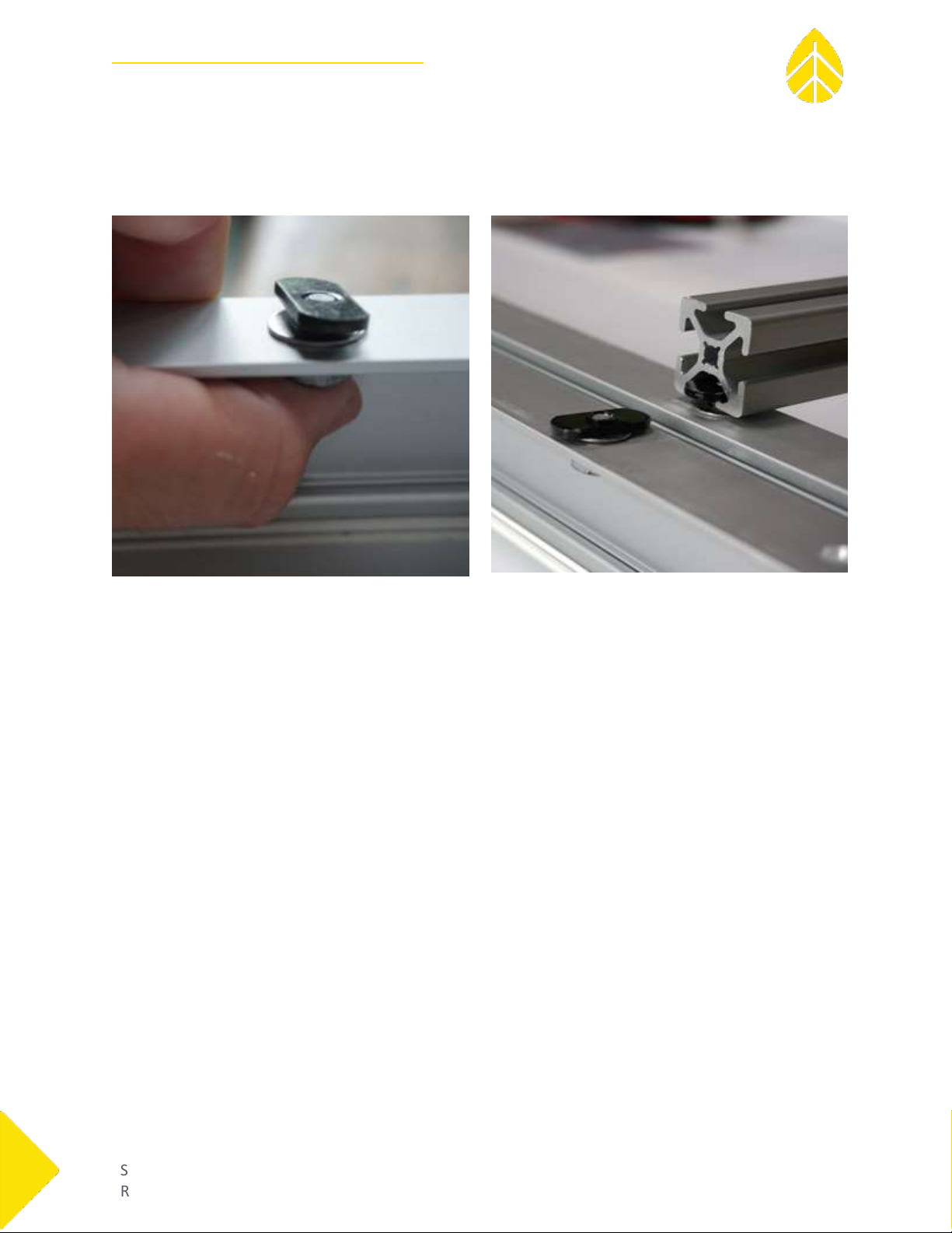
-Slide nuts used in this kit have one side with a lip around the threaded hole. When inserting a slide nut
into an extruded aluminum rail, the lip should always face the center of the rail, not outward towards
the bolt. Failure to do so can prevent the nut from sliding easily inside the channels of the rail.
-Do not overtighten bolts. Overtightening bolts may result in damage to hardware.
-Loctite 242 has been provided in all hardware kits. NRG recommends that Loctite be applied to all slide
nut threads to help prevent loosening over time. Pre-assembled components have Loctite applied
already.
SECTION 1: ASSEMBLING THE ALL-WEATHER SYSTEM TOWER
1.1 Construct and Erect the 2.2m Tower
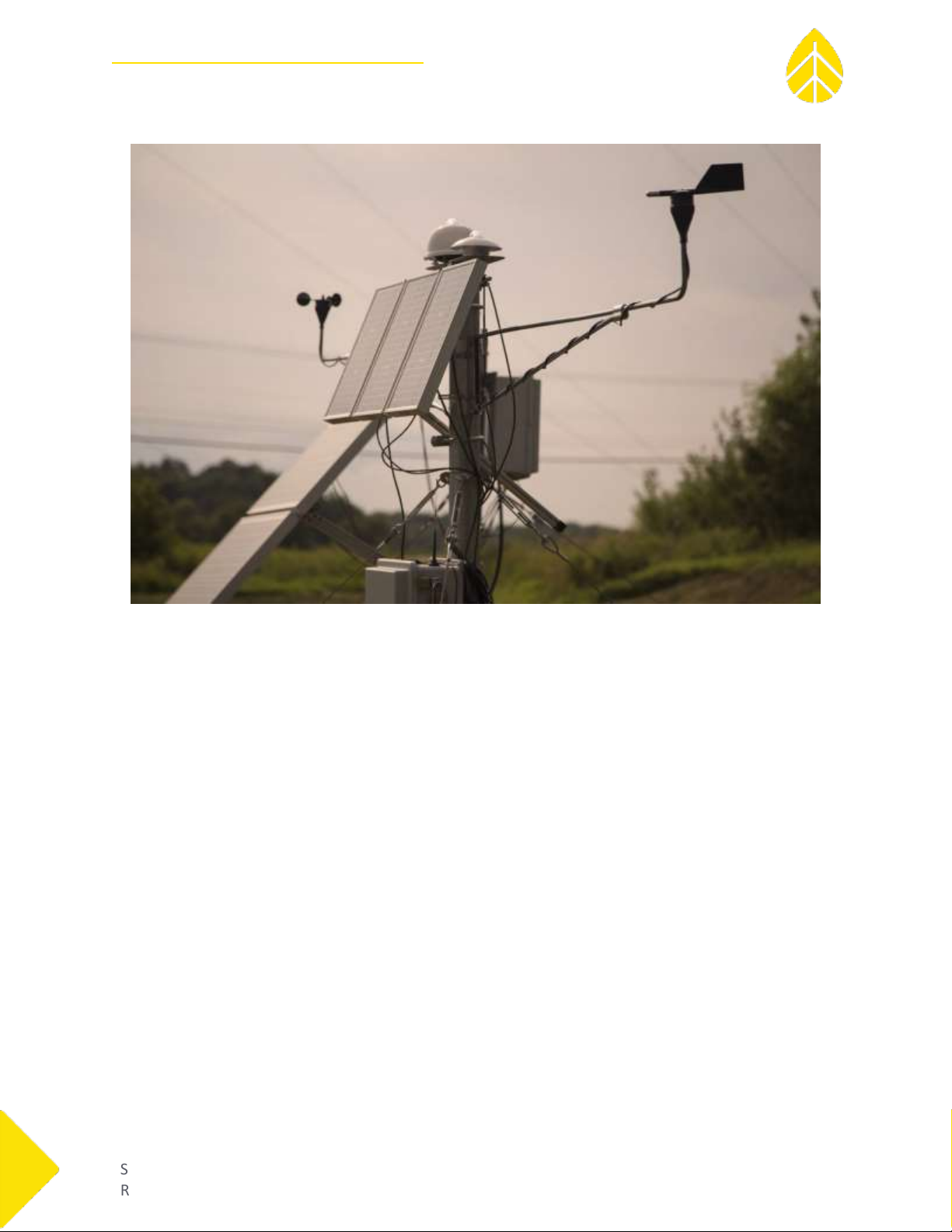
The SRA’s All-Weather PVH Kit includes a 2.2m NRG SRA tower assembly (kit #9118). Construction of this
tower is recommended prior to assembling the PV brackets. Choose a suitable location for the tower
that is close enough for sensor wires (5m length) to reach your NRG SRA System and data logger.
Orient the guy ring and wires so that the PV frame will fit in between two guy wires.
Please read the SRA manual for instructions about how to safely erect the tower. To download the
manual from our website, follow the link below:
https://www.nrgsystems.com/assets/resources/SRA-Manual2.pdf

NRG Instructions
SRA System | All-Weather PVH Kit
SRA_All-Weather_PVH_Kit_Instructions
Rev. 5.0
support@nrgsystems.com | Page 7
18 April 2018
SECTION 2: ASSEMBLING THE PV PANELS & BRACKETS
2.1 Open and unpack all items.
Your All-Weather PVH kit comes packaged in several boxes. Verify that all contents are present and
undamaged.
2.2 Construct the PV Frame
2.2.1 Attach the longest frame pieces (extruded aluminum, 65” length) to the PV panels.
Place PV panels on work surface face-down. Place multiple panels together with the long sides touching
each other. Be careful not to scratch glass surface.
Thread four 1/4-20x.375 hex bolts (#11052) through the PV panel holes indicated (Figure 2-1) and attach
1/4”flat washers and slide nuts (Figure 2-2).
Figure 2-1: PV panel with bolt holes indicated. Figure 2-2: Bolt/washer/nut alignment in PV panel frame.

NRG Instructions
SRA System | All-Weather PVH Kit
SRA_All-Weather_PVH_Kit_Instructions
Rev. 5.0
support@nrgsystems.com | Page 8
18 April 2018
Attach aluminum frame pieces to the panel frames through the slide nuts. Push the bolt head up against
the panel frame to create a gap between washer and slide nut (Figure 2-3). Make sure that the washer
remains between the extruded aluminum and panel (Figure 2-4).
Figure 2-3: Create space for aluminum rail. Figure 2-4: Slide rail onto the slide nuts.
Determine which PV panel will be at the top, then make sure it is flush with the ends of the rails. If more
than one panel is included with your kit, leave a small (about 1/8”) gap between panels on the rails.
2.2.3 Assemble the top tower mount.
Use the diagonal cutters to cut the zip tie packaging holding together all aluminum rails. Remove the
hinged assembly with 12” and 25” rail sections. Remove the V-block/U-bolt assembly from the hardware
box (Figure 2-5, following page).

NRG Instructions
SRA System | All-Weather PVH Kit
SRA_All-Weather_PVH_Kit_Instructions
Rev. 5.0
support@nrgsystems.com | Page 9
18 April 2018
Figure 2-5: Assembled hinges on shorter aluminum rails.
Remove slide nuts from the 1/4-20x1.25 bolts on the V-block, then add Loctite to the threads and
reattach. Slide the V-block assembly onto the 12” rail in the channel opposite of the hinge (Figure 2-6).
Center the block onto the rail and tighten bolts to secure.
Figure 2-6: Slide V-block onto the 12” rail, then center.

NRG Instructions
SRA System | All-Weather PVH Kit
SRA_All-Weather_PVH_Kit_Instructions
Rev. 5.0
support@nrgsystems.com | Page 10
18 April 2018
2.2.4 Attach frame crosspiece and top tower mount to the main assembly.
Thread 1/4-20x.375 bolts (#11697) through small corner brackets and into slide nuts (Figure 2-7).
Figure 2-7: Corner brackets for use with aluminum rails; slide nuts and bolts are attached.
Slide corner brackets onto the ends of the 25” aluminum crosspieces (Figure 2-8). Orient the corner
brackets so that the round hole is touching the crosspieces (the oval holes will attach to the long, PV-
mounted rails). Do not tighten yet.
Figure 2-8: Corner brackets attached to crosspiece. Note the orientation of the hinge.
Slide the crosspieces onto the 65” rails of the main assembly. The top tower mount goes behind the top
PV panel, about 1” from the end. The single 25” crosspiece goes about 24” from the bottom of the
vertical rails. There should be about 1/2” of space at each end of the crosspieces. Tighten all corner
bracket hardware (Figure 2-9, Figure 2-10, following page).

NRG Instructions
SRA System | All-Weather PVH Kit
SRA_All-Weather_PVH_Kit_Instructions
Rev. 5.0
support@nrgsystems.com | Page 11
18 April 2018
Figures 2-9 & 2-10: Tighten aluminum crosspieces into place with appropriate spacing.
2.2.5 Mount the PV panel assembly to the tower.
Loosen the nuts on the 3.5” U-bolt to allow enough space to fit around the tower tube.
Using two people and the 6ft stepladder, lift the assembly up and slide it over the top of the tower. U-
bolt should be approximately 4.5” from the top of the tower for adequate spacing to mount the shelter
box.
Tighten U-bolt nuts with 3/4” wrench (Figure 2-11). Do not overtighten.
Figure 2-11: PV frame & panels mounted to tower with 3.5” ID U-bolt.

NRG Instructions
SRA System | All-Weather PVH Kit
SRA_All-Weather_PVH_Kit_Instructions
Rev. 5.0
support@nrgsystems.com | Page 12
18 April 2018
2.2.6 Attach angle adjustment rails to tower and PV assembly.
The angle adjustment tower mount comes pre-assembled (Figure 2-12). First, remove the slide nuts and
add Loctite, then loosely reattach.
Figure 2-12: Out-of-box assembly of lower tower/angle adjuster mount.
To mount around the tower, first remove the components from one side of the threaded rods (Figure 2-
13). Slide around the tower approximately 44” below the U-bolt and reassemble (Figure 2-14). Ensure
that the threaded rod is evenly distributed on each side of the mount (1.5 –1.75” beyond the innermost
rectangular bracket).
Figure 2-13: Disassembly of one side of lower tower mount.

NRG Instructions
SRA System | All-Weather PVH Kit
SRA_All-Weather_PVH_Kit_Instructions
Rev. 5.0
support@nrgsystems.com | Page 13
18 April 2018
Figure 2-14: Inner components of Figure 12 assembled onto tower.
Complete removal of the outer components is not necessary.
Mount the 48” angle adjustment rails to the outer brackets of the assembly through the slide nuts
(Figure 2-15). Orient the rail such that the hinge attached to the end is at the top and the semicircular
piece is facing the PV frame.
Figure 2-15: Complete assembly of lower tower/angle adjuster mount. Aluminum rail is mounted onto
slide nut and outer bracket is not tightened down.

NRG Instructions
SRA System | All-Weather PVH Kit
SRA_All-Weather_PVH_Kit_Instructions
Rev. 5.0
support@nrgsystems.com | Page 14
18 April 2018
2.2.7 Attach angle adjustment rails to PV frame
Remove the semicircular end pieces from the assembled hinge (Figure 2-16), then remove the slide nuts
from each semicircular piece. Add Loctite to the threads of all three bolts in each hinge.
Figure 2-16: Semicircular end piece removed and attached to PV frame.
Reattach the slide nuts, then slide semicircular end pieces onto the lower PV assembly crosspiece
(Figure 2-16). Line up with angle adjustment rail, then tighten thru-bolt to lock in place. If lined up
correctly, the hinge should assemble easily (Figure 2-17).
Figure 2-17: Assembled & tightened lower tower mount/angle adjuster.

NRG Instructions
SRA System | All-Weather PVH Kit
SRA_All-Weather_PVH_Kit_Instructions
Rev. 5.0
support@nrgsystems.com | Page 15
18 April 2018
2.3 Attach Ventilator Control System (Shelter Box) to Tower.
Thread the provided band clamps through the outer slots of the brackets on the back of the shelter box.
Wrap the band clamps around the tower and secure with a 5/16” hex nut driver. An electric drill or
impactor with a 5/16” nut driver will speed up the tightening process.
Figures 2-18 & 2-19: Shelter box brackets and attachment to the tubular tower.

NRG Instructions
SRA System | All-Weather PVH Kit
SRA_All-Weather_PVH_Kit_Instructions
Rev. 5.0
support@nrgsystems.com | Page 16
18 April 2018
2.4 Mount 110S Temperature Sensor
Using the supplied band clamps, secure the 110S Temperature sensor to the tower directly above the
Shelter Box.
Figure 2-20: NRG 110S Temperature sensor attached to the tubular tower with band clamps.
2.5 Chain the Deep-Cycle Batteries Together
Place the battery (ies) in the black housing box(es).
When using kits 11709 or 11710, it will be necessary to chain the included 12V, deep-cycle batteries
using the supplied cables to create a battery bank.
These batteries contain a significant amount of energy. Use caution or serious injury may
result.
Place the batteries in the supplied battery boxes/enclosures so they are protected from weather
prior to making the connections.
Connect [+] to [+] on the batteries, and connect [-] to [-] using the 4 Gauge (AWG) battery
cables. Use black for [-] and red for [+] terminals.
Connect the 10 AWG 2C cable to the battery bank you have created. At a later step, this cable
will feed into the shelter box and connect to the control system.
Keep the bare ends of the 10 AWG 2C cable separated. Do not let them come in
contact with each other or you.

NRG Instructions
SRA System | All-Weather PVH Kit
SRA_All-Weather_PVH_Kit_Instructions
Rev. 5.0
support@nrgsystems.com | Page 17
18 April 2018
SECTION 3: INSTALLATION OF THE VU01 TO THE SRA TOWER
3.1 Install the SR20 Pyranometer into the VU01 ventilator unit
See section 5.2 and 5.3 of the Hukseflux VU01 manual for detailed instructions on how to install the
SR20 into the VU01 ventilator unit. Excerpts from the Hukseflux manual have been provided below.

NRG Instructions
SRA System | All-Weather PVH Kit
SRA_All-Weather_PVH_Kit_Instructions
Rev. 5.0
support@nrgsystems.com | Page 18
18 April 2018

NRG Instructions
SRA System | All-Weather PVH Kit
SRA_All-Weather_PVH_Kit_Instructions
Rev. 5.0
support@nrgsystems.com | Page 19
18 April 2018
3.2 Connecting the VU01 & Pyranometer to the SRA Tower & SymphoniePRO
3.2.1 Attach the ventilator to the SRA Tower top plate
Mount the ventilator and pyranometer to the top plate of the NRG SRA tower using the appropriate
holes. Level the ventilator and pyranometer. See figure 3-1
Note: NRG SRA Tower top plates produced before September 2017 may not have the appropriate
holes to mount the VU01 ventilator. You can either measure and carefully drill the appropriate holes,
or contact NRG to purchase an updated top plate.
Figure 3-1: Mounted VU01 (with SR20) and a second SR20.
3.2.2 Connect the Hukseflux pyranometer to your SymphoniePRO data logger
The Hukseflux-supplied pyranometer cable has 8 wires. Not all wires are needed to connect to the
SymphoniePRO. Figure 3-2 below illustrates how to make this connection properly.
Figure 3-2

NRG Instructions
SRA System | All-Weather PVH Kit
SRA_All-Weather_PVH_Kit_Instructions
Rev. 5.0
support@nrgsystems.com | Page 20
18 April 2018
SECTION 4: WIRING THE ALL-WEATHER SYSTEM
4.1 Wiring the Ventilator to the Control System
The VU01 is supplied with a multi-conductor cable which plugs into the ventilator. At the other end, the
bare wires connect to the All-Weather Control System according to Figure 4-1 and Table 4-1 below.
Figure 4-1
Note that the blue wire from the VU01 cable connects to the red wire of the supplied NRG 4C cable by a
butt connector. Crimp the connector properly to ensure that the bare wire ends adequately make
contact with each other.
Blue|Red|Pink|Brown|Yellow|Gray|Green|Black
This manual suits for next models
2
Table of contents
Other NRG Systems Inverter manuals
Popular Inverter manuals by other brands

Gen Set
Gen Set MG 8000 I-H Use and maintenance manual

Megaimpulse
Megaimpulse NPG18P14 user manual

Autarco
Autarco PELD10-MII Installation and operation manual

Mitsubishi Electric
Mitsubishi Electric FR-A700 Series manual

ABB
ABB Fimer PVI-10.0/12.5-TL-OUTD product manual

One-Solar
One-Solar TG-2KVA user manual