NSI NRD 8000 User manual

NRD 8000
ADDRESSABLE
DIMMER PACK
OPERATION MANUAL

NSI NRD 8000 ADDRESSABLE DIMMER PACK
INTRODUCTION
The NSI NRD 8000 is a rack mountable eight channel dimmer system that provides 1200
watts per channel or a maximum power c
apacity of 9,600 watts.
The NRD 8000 is fully user addressable allowing assignment of up to eight of a possible
128 channels. Microplex technology developed by NSI for the stage lighting industry, is
the electrical marriage of microprocessor technology with digitally controlled
multiplexing. This technology allows all NSI Lighting components to be connected with
standard three conductor microphone audio cables or even audio snakes. System
expansion is further simplified through the abi1ity to daisy chai
n additional dimmer packs
to an existing system. This application of microplex technology makes system set up and
operation easy and convenient. In addition, NSI Products are compatible with most other
manufacturer’s lighting products, which use the same
microphone cable interface.
Our philosophy at NSI is to utilize only the highest quality components in the design and
manufacturing of our products. Problems that often plague dimmers such as flickering
lights, buzzing in audio equipment, and t
riac failure are minimized in NSI products. Each
output of the NRD 8000 is fully filtered with industrial toroidal devices. In place of triacs,
NSI only uses professional grade dual SCR’s.
You can be confident your NSI Dimmer Packs feature the best in pe
rformance and
reliability standards available.

SPECIFICATIONS
Eight
No. of Channels:
Power Output per Channel: 1200 Watts
Total Maximum Power Output : 9,600 Watts
Filtering:
Serial Control System:
Input Voltage To Response Time:
Control Isolation:
+ 15 V. DC -Available to Controller:
Dimensions:
HxWxD
Mounting Spec. 18 3/4 "
NSI
"Microplex"
50 MSEC
1200 Volt HV
400 MA
5 1/4" x 19" x 10 1/4"
(from hole centers):
(8) Toroidal Chokes 400 USEC.

Channels 12345/J2 J1
ADDRESSING
Each NSI dimmer pack i
s fully user addressable to receive any of 128 possible control
channels. Control channels may be assigned in increments of four by addressing the NRD
8000 to receive them. To accomplish this simply position the address select switches as
described in the following chart.
Note:
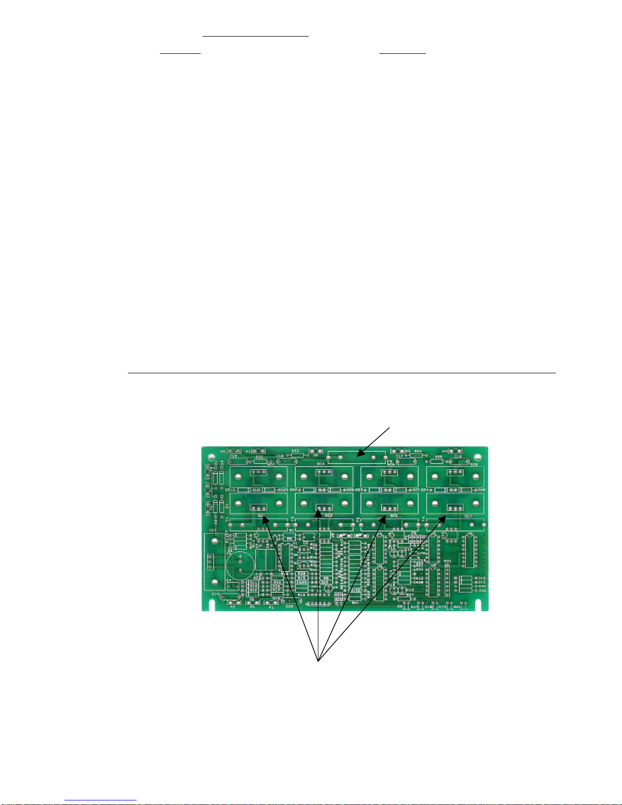
New Style units have six position dipswitches where as dipswitches 1-6 are
indicated below. Old style units are functionally the same but offered 4 position
dipswitches. Internal jumpers where as J1, J2 are indicated below.
1-4Off Off Off Off Off N/A
5-8On Off Off Off Off N/A
9-12 Off On Off Off Off N/A
13-16 On On Off Off Off N/A
17-20 Off Off On Off Off N/A
21-24 On Off On Off Off N/A
25-28 Off On On Off Off N/A
29-32 On On On Off Off N/A
33-36 Off Off Off On Off N/A
37-40 On Off Off On Off N/A
41-44 Off On Off On Off N/A
45-48 On On Off On Off N/A
49-52 Off Off On On Off N/A
53-56 On Off On On Off N/A
57-60 Off On On On Off N/A
61-64 On On On On Off N/A
65-68 Off Off Off Off On N/A
69-72 On Off Off Off On N/A
73-76 Off On Off Off On N/A
77-80 On On Off Off On N/A
81-84 Off Off On Off On N/A
85-88 On Off On Off On N/A
89-92 Off On On Off On N/A
93-96 On On On Off On N/A
97-100 Off Off Off On On N/A
101-104 On Off Off On On N/A
105-108 Off On Off On On N/A
109-112 On On Off On On N/A
113-116 Off Off On On On N/A
117-120 On Off On On On N/A
121-124 Off On On On On N/A
125-128 On On On On On N/A
The NRD 8000 is actually two
four channel dimmers coupled together to provide eight channels
of dimming in a single rack mountable package. Each group of four channels has its own
address switches. These controls channels are addressed in increments of four as outlined in the
chart above.
IMPORTANT: All NSI dimmer packs are shipped from the factory addressed for channels 1 -4. Units must be
readdressed (see chart above) before being capable of receiving any other channels.

AC OUTPUT RECEPTACLES
Dual standard Leviton AC ou
tlet receptacles are provided for each channel of the NRD 8000. These
receptacles provide power to the lamps in your lighting system. The amount of power supplied to these
outlets control the intensity of the lights they drive. Multiplexed signals received
from your NSI
controller are translated into power levels to achieve desired light intensity. Each dual receptacle
corresponds to a single channel with the maximum power capabilities described in the specifications
section of this manual. Under no circums
tance should maximum recommended power capabilities be
exceeded. Exceeding the rating may
be hazardous and will void your warranty. Most lamps, fixtures
and rain lights may be connected to these outlets. Do
not connect any other electrical appliances or
e
quipment to the dimmer packs.
MICROPLEX INPUTS
Both male and female Microplex connectors may be used for input signals. Mico
-
plex technology
allows your system to be connected using standard microphone cables or even audio snakes.
Digitally coded s
ignals may be received from your NSI controller or another dimmer pack. The
Microplex system also provides D.C. phantom power to your controller. Up to 128 individual
control channels plus phantom power to your controller may be transmitter through a sin
gle
microphone cable.
MICROPLEX EXPANSION
The male and female Microplex connectors are wired in parallel allowing either one to be used for
input or output of control signals. When used as an output, the Microplex connectors will provide
control signals
to another dimmer pack. This is called daisy chaining and makes expansion of
your system easy. Up to 128 individual control signals may be sent through NSI dimmer packs
via a standard microphone cable.

CONTROL STATUS
INDICATORS
Individual yellow LED' s
(Light Emitting Diodes) indicate when channels are active. This feature is
an excellent trouble shooting tool in identifying possible problems with signal transmissions or
defective lamps and fixtures
POWER ON INDICATOR
This green LED (Light Emitting Dio
de) will light whenever the dimmer pack is receiving AC power
and functioning properly.
AUTO TEST
This built
-
in function allows you to connect and test lamps at full intensity without the need of a
controller. When dipswitch 6 is off with a controller absent lamps will light to full intensity. Internal
jumper J1 is used in place of dipswitch 6 on 4 dipswitch units.
CIRCUIT PROTECTION
The NRD 8000 is equipped with safety circuit interruption devices to ensure protection from
overloading or shorted circuits. The NRD 8000 utilizes resetable external circuit breakers for each
individual channel as well as internal fusing.
MOUNTING
The NSI NRD 8000 dimmer pack may be mounted in standard EIA 10” racks. The NRD 8000 is
provided with two mounting flanges or ears designed for securing to the rack mounting rails.
Most standard rack rails are already properly drilled to accept mounting 19” EIA standards for
industrial equipment, however in some cases you may need to drill holes to accommodate your
dimmer pack. When doing this ensure hole spacing is accurate before attempting to drill.
WIRING FOR AC POWER
The NRD 8000 is equipped with a standard screw terminal connection to facilitate customer
wiring for AC power. NSI recommends only qualified individuals with a knowledge of
electricity attempt to wire the NRD 8000 to electrical power. NSI assumes no liability for
personal injury, lamp failure, or other equipment damage when the unit is improperly
connected to an electrical service or connected by unqualified personn
el.
It is important to verify wiring before connecting or energizing the service main. Mis
-
wiring
may cause the 3/10 amp internal power supply fuses to blow. Circuit damage and blown lamps
may also result from improper wiring.

NEUTRAL WIRE MUST BE CONNE
CTED TO BOTH NEUTRAL TERMINALS
Double check for correct connection.
ELECTRICAL SERVICE MUST BE FUSED AT 40 AMPS MAXIMUM
NOTES:
Amperage requirements of power service may be reduced for decreased maximum power
(ie. 30 amps for 1000w/channel).
The NRD 8000 m
ay be connected to either of the following types of electrical power services as
illustrated below. It is recommended that a suitable power connector and cable (such as a standard
4 prong range or dryer plug) be attached to the unit for portable operation.
The NRD 8000 is actually two 4 channel dimmers coupled together for the flexibility of eight
independent channels in one rack mount package. The NRD 8000 may be wired to achieve the
maximum power rating of 1,200 watts per channel or a total of 9,600 watts. The system may also be
configured to provide two 1,200 watt outputs to each of four channels for a total of 2,400 watts per
channel by setting both addressing switches the same. It is important to know what your power
requirements are before making conn
ections to the dimmer.

OPERATIONAL HINTS
1) Use a power source on a circuit separate from your audio system.
2) Ensure that the rating of the breaker or fuse for the power source chosen is adequate. The
required rating (in amps) of the breaker or fuse may
be calculated with the following formula:
I =P/E
Where I = the current (in amps)
P = the power (in watts)
and
E = the voltage
(in volts)
3) Always use quality 12 gauge (or heavier) grounded power cables for input power.
4) Always use quality 18 gauge (or
heavier) grounded power cables for output power.
5) Avoid placing AC power cables or extension cords for lighting near sensitive audio cables
(guitar cords, mic cables, audio snakes, etc.).
6) Avoid blocking the ventilation holes on the sides of your dimm
er pack. It is very important your
unit has this ventilation to avoid possible damage which may void the warranty.

Caution: Please disconnect power before removing cover for service as high voltage is otherwise present.
TROUBLESHOOTING GUIDE
SYMPTOM CHECK LIST
NO OUTPUT, LED INDICATORS SHOW 1. CHECK CHANNEL FUSES. (REFER TO
STATUS OKAY DIAGRAM BELOW)
NO POWER 1. CHECK LINE FUSE (REFER TO DIAGRAM
BELOW)
2. IF FUSE BLOWS AFTER REPLACEMENT CHECK
TRANSFORMER.
1.CHECK CHANNELS FUSES
2. CHECK FIXTURE LAMPS
3. CHECK BLACKOUT FREATURE ON CONSOLE
4. CHECK DIPSWITCH ASSIGNMENT
5. CHECK MAXIMUM DIMMER ASSIGNMENT ON
CONTROL CONSOLE
6. CHECK SOFTPATCH ON CONTROL CONSOLE
1. CHECK DIP SWITCH ASSIGNMENT.
2. CHECK SIGNAL CABLE
3. CHECK MAXIMUM DIMMER ASSIGNMENT AT
CONSOLE
4. CHECK OUTPUT MODE OF CONTROL CONSOLE.
1. TRANSMISSION LENGTH MAY BE A PROBLEM. GET
CONSOLE CLOSER WlTH A SHORTER CABLE TO VERIFY.
REMEDY MAY BE THE USE OF 18 GAUGE CABLE OR AN
EXTERNAL POWER SUPPLY AT THE CONSOLE. (CALL
DEALER OR NSI TECHNICAL SERVICES FOR DETAILS).
2. CHECK PRE-HEAT SETTING OF CONSOLE.
LIGHTS ALWAYS OFF
LIGHTS ON ALWAYS
LED INDICATORS ON DIMMER PACK FLICKER
OR GLOW DIMLY.
LINE FUSE
~ STANDARD 3/10 AMP SLO BLO
CHANNEL FUSE LOCATION
REPLACE WITH VALUES AS LISTED BELOW
ND4600 8 AMP FAST BLO
ND5000 15 AMP FAST BLO NRD 800015 AMP FAST BLO
IF PROBLEMS PERSIST CONT ACT YOUR NEAREST NSI AUTHORIZED DEALER OR NSI TECHNICAL SERVICES
AT 800-864-2502 BETWEEN THE HOURS OF 8:00 AM TO 5:00 PM PST MONDAY THRU FRIDAY.

NSI CORPORATION LIMITED WARRANTY
NSI Corporation warrants new electronics products to be free from defective materials and
workmanship for a period of two (2) years from the date of purchase to the original owner when
purchased from an authorized NSI dealer.
The purchaser is responsible for completing and mailing to NSI, within 15 days of purchase, the
warranty registration card enclosed with each product. NSI products that have been subject to
accident, alteration, abuse, or defacement of the serial number are not covered by this warranty.
The normal wear and tear of items such as knobs, jacks, and switches are not covered under this
warranty.
If your NSI product requires service during the warranty period, NS
I will repair or replace, at its
option, defective materials provided you have identified yourself as the original owner of the
product to NSI or any authorized NSI dealer. Transportation charges to and from an authorized
dealer or the NSI factory for repair shall be the responsibility of the owner. All products
returned to NSI must have factory authorization for return prior to shipping.
NSI Corporation is not liable for any incidental or consequential damages resulting from defect
or failure other than repairs of the NSI product subject to the terms of this warranty. This
warranty gives you specific legal rights, and you may have other rights which vary from state to
state. This warranty is expressly in lieu of all other agreements and warranties expressed or
implied except as may be otherwise required by law.
Table of contents
Other NSI Dimmer manuals
Popular Dimmer manuals by other brands

Theatrelight
Theatrelight NEBULA Quick operation

Acclaim Lighting
Acclaim Lighting X-Dimmer-3 PRO User instructions

HomeMatic
HomeMatic HM-LC-Dim1T-FM Installation and operating manual

Aeon Labs
Aeon Labs Aeotec Nano Dimmer user guide

Acclaim Lighting
Acclaim Lighting AL-DIMMER-3F User instructions

PEHA
PEHA 492 AB O.A. Installation and operating instructions