Table of Contents
MAN-G-BELIG (Ver. 1.200)
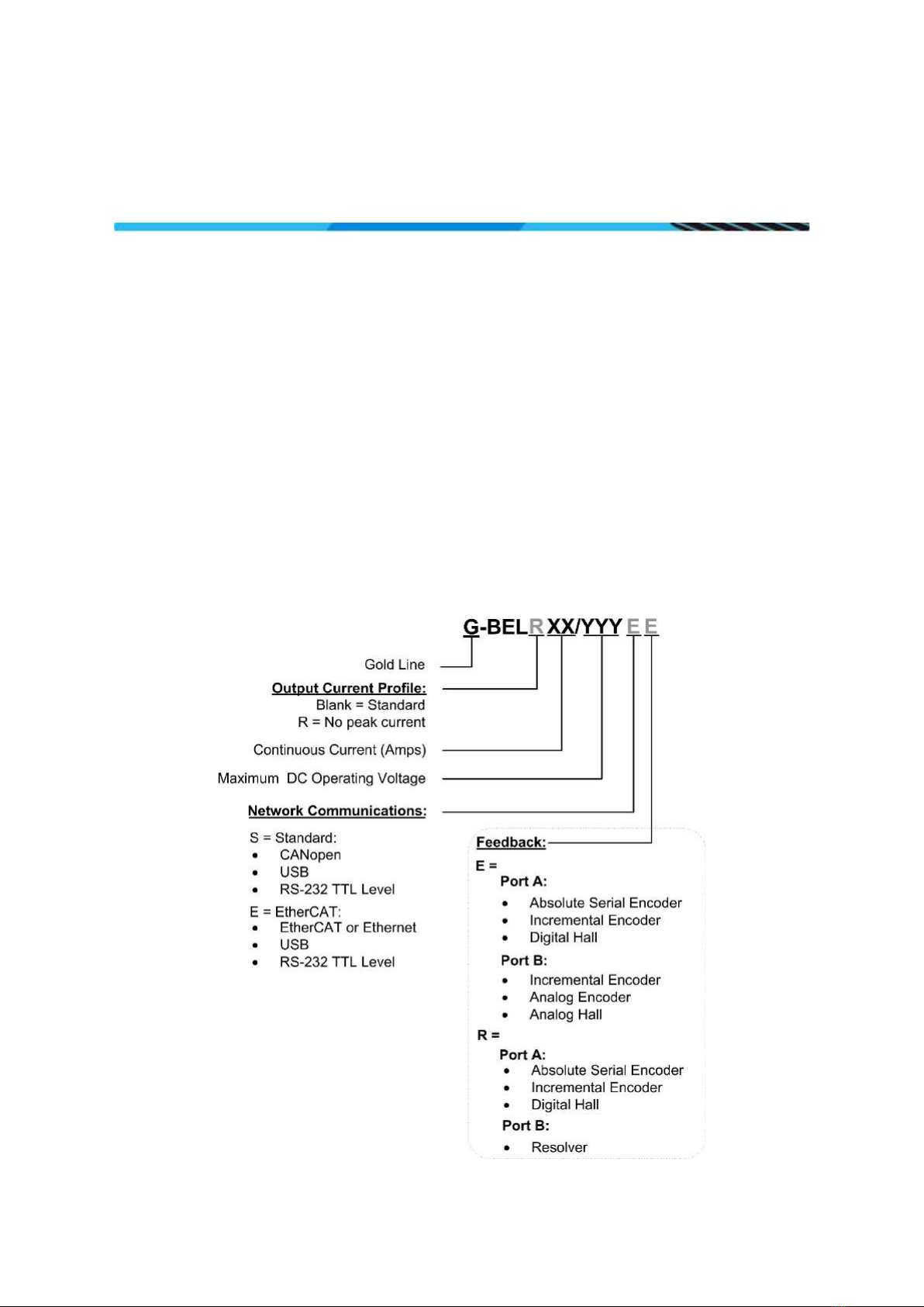
|Connector J2 |www.elmomc.com
4
9.5.4.1 Single Power Supply ..................................................................... 28
9.5.4.2 Shared Supply............................................................................... 30
9.6 Connector J2 - Feedback, Analog Inputs, RS-232, USB, EtherCAT, Ethernet, and CAN 31
9.6.1 Feedback Port A ............................................................................................ 34
9.6.1.1 Incremental Encoder .................................................................... 34
9.6.1.2 Hall Sensors .................................................................................. 35
9.6.1.3 Absolute Serial Encoder ............................................................... 36
9.6.1.4 Hiperface ...................................................................................... 38
9.6.2 Feedback Port B............................................................................................. 39
9.6.2.1 Incremental Encoder .................................................................... 39
9.6.2.2 Interpolated Analog (Sine/Cosine) Encoder................................. 40
9.6.2.3 Resolver........................................................................................ 41
9.6.3 Port C – Emulated Encoder Output ............................................................... 42
9.6.4 Analog Inputs................................................................................................. 42
9.6.4.1 Analog Input 1 .............................................................................. 43
9.6.4.2 Analog Input 2 .............................................................................. 44
9.6.5 RS232 TTL Logic Level.................................................................................... 44
9.6.6 USB 2.0 .......................................................................................................... 46
9.6.7 EtherCAT/Ethernet ........................................................................................ 47
9.6.8 CAN................................................................................................................ 48
9.7 Connector J1 - Digital I/O, Analog Inputs, LEDs, and STO............................................. 49
9.7.1 Digital Inputs ................................................................................................. 51
9.7.1.1 TTL voltage level ........................................................................... 51
9.7.2 Digital Outputs............................................................................................... 52
9.7.2.1 Isolated Open Collector and Open Emitter .................................. 52
9.7.3 Analog Inputs................................................................................................. 52
9.7.4 STO Input Interfaces - TTL Mode................................................................... 53
9.7.5 EtherCAT Status Indicator ............................................................................. 53
Chapter 10: Powering Up..................................................................................................54
10.1 Initializing the System................................................................................................... 54
Chapter 11: Heat Dissipation ............................................................................................55
11.1 Thermal Data ................................................................................................................ 55
11.2 Heat Dissipation Data ................................................................................................... 55
11.3 How to Use the Charts.................................................................................................. 56
Chapter 12: Dimensions ...................................................................................................57