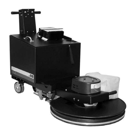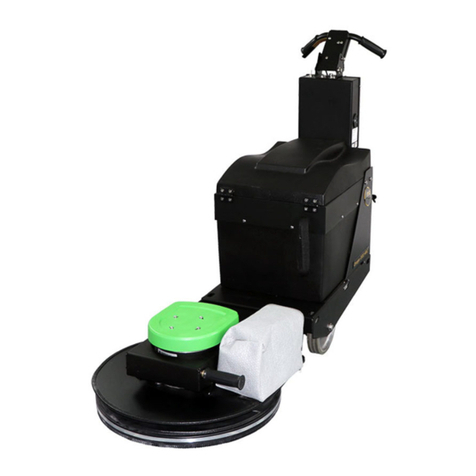
Wheel Drive Motor
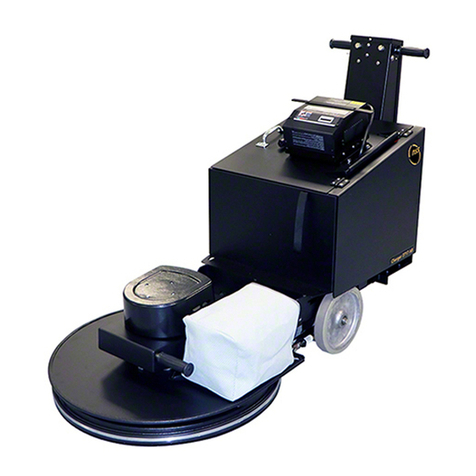
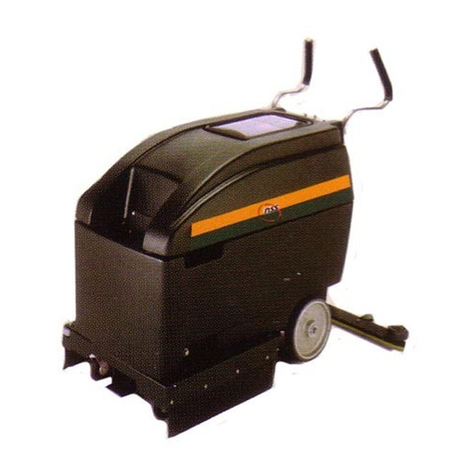
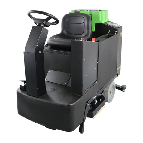
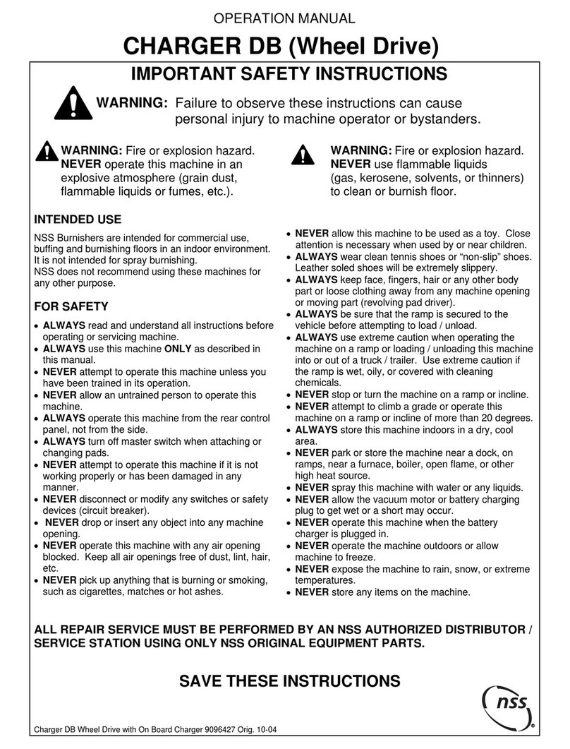
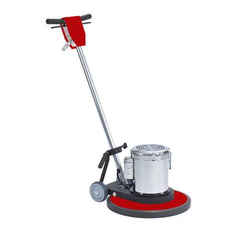
•VS machines are powered by a 36-volt drive motor.
•The speed is electronically controlled for smooth
increase and decrease of speed.
•The motor moves the drive wheels through a chain
and sprocket system.
•This motor has carbon brushes that must be
serviced on a regular basis.
Refer to the maintenance section later in this book.
Battery Packages
•These machines utilize a 36-volt system, and are
available with three (3) 12-volt, 210-Amp Hour
Batteries.
•Consult your local NSS authorized distributor for
application recommendations.
•Do not substitute smaller batteries, as the balance
of the machine will be affected.
MACHINE OPERATION
General Information
This machine works best with dry polishing or
burnishing. Use mop on restorers rather than spray
buff systems to restore the shine.
Spray buffing is time consuming, uses more pads
because they become loaded with floor finish, and
can cause overloading of the machine’s circuit
breaker.
Preparing the Machine for use
Install the batteries:
•Always wear protective glasses and clothing when
handling batteries.
See Battery Warnings on page 2.
•Turn off all switches, unlatch the clasps and slide
the housing forward to expose the battery
compartment.
•Batteries are heavy -use two people to install.
•Refer to wiring diagram inside the battery
compartment. Align batteries in compartment as
shown on diagram.
•Install battery cables as shown on wiring diagram.
•Tighten bolts and hex nuts with a wrench.
Caution: Do not short across two terminals with a
wrench.
Caution: Loose or improper battery connections
will cause battery or machine damage and possible
personal injury.
•Install terminal boots over terminals to complete
installation.
Check the Battery Charge
Turn the switch to the “I” position. Check to see that
the indicator light is on. With master switch on, check
battery meter for charge indication.
•When the needle is in the red area on the left side,
marked “recharge”, the batteries are too low to
operate and should be recharged.
•When the needle is in the green area, the batteries
are within the high to low working range.
•When the needle is in the red area on the right side
of the gauge it indicates the level of battery charge
while connected to the charger.
•When needle is in the far right, red area, shown as
high, and the automatic charger has shut off,
charging of the batteries is complete.
Pad Installation / Changing
Lower the back of the machine to Position 3 (see
bottom figure on page 4), by lifting up on the release
knob with one hand, and with your other hand on the
operator handle, gently lower the back of the machine
until it rest on the floor.
•Make sure that the correct pad (7/8" to 1") X 20" is
being installed.
•Place the pad flat on the floor, and remove the
center hole of the pad, step on the center of the pad
to compress the edges around the center hole. This
will allow easier installation of the pad holding cup.
•With the machine in the pad changing position,
carefully center the pad on the driver.
Caution: Pads must be installed concentric (evenly
aligned) with the outside edge of the pad driver.
Failure to follow these precautions will cause
excessive machine vibration, a reduction in pad life
and produce unsatisfactory burnishing results.
•Place the pad grabber in the center hole of the pad.
•Holding the pad driver and pad, push upward on the
pad grabber until the spring clip has clicked twice.
Caution: Failure to install the pad grabber tightly
may allow the pad to be thrown from the driver.
There is a wide range of pads and brushes available
for the many burnishing applications of this machine.
Consult your local NSS authorized distributor for
application recommendations
Transporting the Machine to the work site
From the pad changing position raise the back of the
machine up by lifting up on the operator’s handle with
both hands, until you hear the adjustment knob “click”
into position. The machine is now ready for transport.
See bottom figure on page 4.
•On pad assist machines, push the machine to the
work site turn the master switch to “I”, and pull up on
the dead man lever.
•On VS models, adjust the speed control knob to an
appropriate speed, turn the master switch to “I”, and
pull up on the dead man lever.
Operating the Machine
From the transport position raise the back of the
machine up by lifting up on the operator’s handle with
both hands. The machine will automatically stop in
position 1, see bottom figure on page 4.
•Turn the master switch to “I”; check the level of
battery work range (put machine on “charge” if not in
the high range).
https://harrissupplyind.com-ToOrderPartsCall608-268-8080
