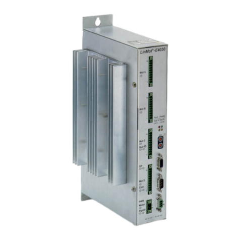
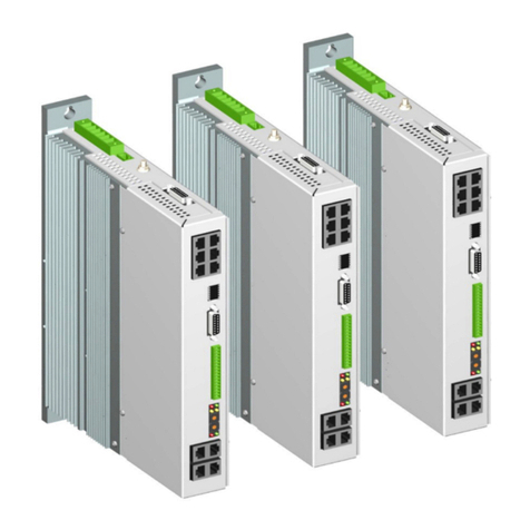
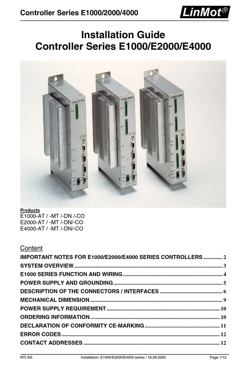
NTI AG LinMot E100-CO User manual

Documentation of the CANopen Interface of the following
Controllers:
- E100-CO
- E200-CO
- E400-CO
- E1000-CO
- E2000-CO
- E4000-CO
CANopen Interface 1.3.14
Usermanual

L
i
n
M
o
t
CANopen Interface
Page 2/16 Usermanual CANopen Interface / 14.09.2005 NTI AG / LinMot
© 2005 NTI Ltd
This work is protected by copyright.
Under the copyright laws, this publication may not be reproduced or transmitted in any form, electronic or mechanical, including
photocopying,
recording, microfilm, storing in an information retrieval system, not even for didactical use, or translating, in whole or in
part, without the prior written consent of NTI Ltd.
LinMot® is a registered trademark of NTI Ltd.
Note
The information in this documentation reflects the stage of development at the time of press and is therefore without obligation.
NTI Ltd. reserves itself the right to make changes at any time and without notice to reflect further technical advance or product
improvement. Please refer to the latest edition of our "General business terms"
Document version 1.3.14 / FM, Sept. 2005

CANopen Interface
L
i
n
M
o
t
NTI AG / LinMot Usermanual CANopen Interface / 14.09.2005 Page 3/16
1. SYSTEM OVERVIEW ......................................................................................................... 4
2. CONNECTING TO THE CAN BUS ...................................................................................... 4
Pinout of the COM Connector: .......................................................................................... 4
3. CANOPEN PARAMETERS ................................................................................................. 4
4. MAPPING OF THE PDO’S................................................................................................. 7
Mapping Table ...................................................................................................................7
Receive PDO’s: .............................................................................................................. 7
Transmit PDO’s: ............................................................................................................ 7
Default Identifier:........................................................................................................... 8
5. MOTOR COMMANDS........................................................................................................ 9
6. CONTROL WORD ........................................................................................................... 10
7. STATUS WORD .............................................................................................................. 10
8. STATEMACHINE............................................................................................................. 11
9. ERRORS AND WARNINGS............................................................................................... 12
Bit definitions for the error state of the motors and the system: .................................. 12
Bit-Definitionen der Motor Warnungen:...................................................................... 12
10. UNITS ........................................................................................................................ 13
11. OBJECT DICTIONARY................................................................................................. 13
12. EXAMPLE .................................................................................................................. 15

L
i
n
M
o
t
CANopen Interface
Page 4/16 Usermanual CANopen Interface / 14.09.2005 NTI AG / LinMot
1. System overview
The LinMot CANopen controllers Ex00-CO support the Communication Profile CiA DS301.
Further information on CANopen can be found under: http://www.can-cia.de/
The following resources are available:
1-5 T_PDO
1-5 R_PDO
1 T_SDO
1 R_SDO
The supported protocols include:
- Node Guarding
- PDO acyclic with inhibit time
- SDO Upload and Download
- NMT (Start, Stop, Enter PreOp, Reset Node, Reset Communication)
- Boot-Up Message
It supports all specified baud rates from 20kBaud to 1Mbaud. The baud rate can be selected
by parameter or direct by BTR register.
The CANBus is on the COM Connector of the controller.
2. Connecting to the CAN bus
Pinout of the COM Connector:
DSBU 9 male:
Pin 1 RS-485 Y Pin 6 RS-485 B
Pin 2 RS-232 TX Pin 7 RS-485 Z
Pin 3 RS-232 RX Pin 8 CAN L
Pin 4 RS-485 A Pin 9 CAN H
Pin 5 GND
3. CANopen Parameters
The CANopen Servo Controllers have an additional parameter tree branch, which can be
configured with the distributed LinMot Talk software. With these parameters, the CANopen
behaviour can be configured. The software LinMot talk can be downloaded from
http://www.linmot.com under the section download, software & manuals.

CANopen Interface
L
i
n
M
o
t
NTI AG / LinMot Usermanual CANopen Interface / 14.09.2005 Page 5/16
Dis-/Enable With the Dis-/Enable parameter the LinMot servo controller can be set
as normal AT servo controller. So the system can be run without the
CANopen going online. So in first step the system can be configured
and run without any bus connection.
CANopen\ Dis-/Enable
Disable Servo controller behaves as an AT servo controller
without CANopen.
Enable Servo controller runs only with a CANopen
connection.
Baudrate The Baudrate parameter defines the CAN bus baudrate for the
CANopen connection.
CANopen\ Baudrate
10 kBit/s CAN bus baud rate = 10 kBit/s
20 kBit/s CAN bus baud rate = 20 kBit/s
50 kBit/s CAN bus baud rate = 50 kBit/s
100 kBit/s CAN bus baud rate = 100 kBit/s
125 kBit/s CAN bus baud rate = 125 kBit/s
250 kBit/s CAN bus baud rate = 250 kBit/s
500 kBit/s CAN bus baud rate = 500 kBit/s
800 kBit/s CAN bus baud rate = 800 kBit/s
1 Mbit/s CAN bus baud rate = 1 Mbit/s
By BTR CAN bus baud rate is according the Bit Timing
Register
BTR value Bit Timing Register, when option “By BTR” is
selected.
Node ID The Node ID parameter defines the source of the Node ID.
CANopen\ Node ID
Switches The Node ID is determined by the two Hex Switches
Parameter The Node ID is determined by parameter setting
Node ID value The Node ID, when “parameter” is selected
Mapping TPDO1 This parameters define the mapping of the transmit PDO1. Each PDO
can have 4 variables mapped (all variables are 16 bit)
ID high
ID low

L
i
n
M
o
t
CANopen Interface
Page 6/16 Usermanual CANopen Interface / 14.09.2005 NTI AG / LinMot
CANopen\ Advanced \ Mapping \ TPDO1
Status Status word
Ret Val 1 Return value of CMD Interface 1 (Read Memory
command)
Ret Val 2 Return value of CMD Interface 2 (Read Memory
command)
Ret Val 3 Return value of CMD Interface 3 (Read Memory
command)
Ret Val 4 Return value of CMD Interface 4 (Read Memory
command)
Encoder Count Actual Encoder value on ME applications
DC Link
Voltage
DC Link Voltage (motor supply). The unit is
102.539mV
By Address The mapping is defined by addresses
Addresses This defines the addresses of the mapping, when no
other option is selected. (0 = no mapping)
Mapping TPDO2..5 This parameters define the mapping of the transmit PDO1..5. Each
PDO can have 4 variables mapped (all variables are 16 bit)
CANopen\ Advanced \ Mapping \ TPDO2..5
Actual Position
Mot X
Contains the actual Position of the motor X
Actual Current
Mot X
Contains the actual Current of the motor X
Warning Mot X Warnings of motor X
Error Mot X Errors of motor X
Demand
Position Mot X
Actual demand position of the motor X
Position Error
Mot X
Difference between demand and actual position of
motor x
By Address The mapping is defined by addresses
Addresses This defines the addresses of the mapping, when no
other option is selected. (0 = no mapping)
Mapping RPDO1 This parameters define the mapping of the receive PDO1. Each PDO
can have 4 variables mapped (all variables are 16 bit)
CANopen\ Advanced \ Mapping \ RPDO1
Control Control word
By Address The mapping is defined by addresses
Addresses This defines the addresses of the mapping, when no
other option is selected. (0 = no mapping)
Mapping RPDO2..5This parameters define the mapping of the receive PDO2..5. Each PDO
can have 4 variables mapped (all variables are 16 bit)
CANopen\ Advanced \ Mapping \ RPDO2..5
Command Command Interface X (4 Words)
By Address The mapping is defined by addresses

CANopen Interface
L
i
n
M
o
t
NTI AG / LinMot Usermanual CANopen Interface / 14.09.2005 Page 7/16
Addresses This defines the addresses of the mapping, when no
other option is selected. (0 = no mapping)
Ressources TPDO1..5 This parameters define the bus parameters of the transmit
PDO1..5.
CANopen\ Advanced \ Ressources \ TPDO1..5
Disable The PDO is deactivated
Enable The PDO is activated
Transmission
Type
This defines the transmission type according DS
301. Default Value is 254
Inhibit Time Defines the time between two send events in ms.
Ressources RPDO1..5 This parameters define the bus parameters of the recieve
PDO1..5.
CANopen\ Advanced \ Ressources \ RPDO1..5
Disable The PDO is deactivated
Enable The PDO is activated
4. Mapping of the PDO’s
Mapping Table
The PDO’s are default mapped according the following scheme:
Receive PDO’s:
R_PDO1 R_PDO2 R_PDO3 R_PDO4 R_PDO5
Control Word CMD MOT A CMD MOT B CMD MOT C CMD MOT D
Par 1 Par 1 Par 1 Par 1
Par 2 Par 2 Par 2 Par 2
Par 3 Par 3 Par 3 Par 3
Transmit PDO’s:
T_PDO1 T_PDO2 T_PDO3 T_PDO4 T_PDO5
Status Word A Pos Mot A A Pos Mot B A Pos Mot C A Pos Mot D
Current MA Current Mot B Current Mot C Current Mot D
Warn Mot A Warn Mot B Warn Mot C Warn Mot D
Error Mot A Error Mot B Error Mot C Error Mot D
If the application requires, the mapping can be completely changed by the advanced
parameter settings. Many applications do not require to use all resources.

L
i
n
M
o
t
CANopen Interface
Page 8/16 Usermanual CANopen Interface / 14.09.2005 NTI AG / LinMot
Default Identifier:
The default identifiers (11 Bit identifier) are allocated by the following scheme:
10 9 8 7 6 5 4 3 2 1 0
Function Code Node ID
This results in the following table:
Object Function Code
(binary)
COB ID (hex) Object for Comm. Parameter /
Mapping
NMT 0000 00h - / -
SYNC 0001 80h 1005h / 1006h
Emergency 0001 81h – FFh - / -
T_PDO1 0011 181h – 1FFh 1800h
T_PDO2 0101 281h – 2FFh 1801h
T_PDO3 0111 381h – 3FFh 1802h
T_PDO4 1001 481h – 4FFh 1803h
T_PDO5 1101 681h – 6BFh 1804h
R_PDO1 0100 201h – 27Fh 1400h
R_PDO2 0110 301h – 37Fh 1401h
R_PDO3 1000 401h – 47Fh 1402h
R_PDO4 1010 501h – 57Fh 1403h
R_PDO5 1111 781h – 7BFh 1404h
T_SDO 1011 581h – 5FFh - / -
R_SDO 1100 601h – 67Fh - / -
In the Pre-Operational state, this can be changed with SDO downloads by the master.

CANopen Interface
L
i
n
M
o
t
NTI AG / LinMot Usermanual CANopen Interface / 14.09.2005 Page 9/16
5. Motor Commands
The commands for the motors are defined as followed:
CMD Mot X:
15 14 13 12 11 10 9 8 7 6 5 4 3 2 1 0
Toggle MA MB MC MD Command ID
The Toggle Bit corresponds to the “CMD Toggle response Mot X”-flag in the status word.
With the Bits MA..MD the command selects the motor. The command can be used for 1 to 4 Motors.
The following Command ID’s are defined:
ID Description
0 No operation
1 Goto Position (Par 1 = Position)
2 Goto Position with max Speed (Par 1 = Position, Par 2 = max. Speed)
3 Goto Position with max Speed and Acceleration (Par 1 = Position, Par 2 = max Speed,
Par 3 = max. Acceleration)
4 Set Filter Parameter (Par 1 = max Speed, Par 2 = max. Acceleration, Par 3 = max.
Current)
5 Redefine Position (Par 1 = Position to redefine to)
6 Move Home Position (Par 1 = Position Difference)
7 PVA Mode (Par 1 = Position, Par 2 = Speed, Par 3 = Acceleration)
16 Run Curve (Par 1 = Curve Number)
17 Run Curve with curve speed (Par 1 = Curve Number, Par 2 = Curve Speed)
18 Run Curve with curve Speed and Amplitude (Par 1 = Curve Number, Par 2 = Curve
Speed, Par 3 = Curve Amplitude)
19 Run curve with auto Offset (Par 1 = Curve Number)
20 Run Curve with Auto Offset, curve Speed and Amplitude (Par 1 = Curve Number, Par 2 =
Curve Speed, Par 3 = Curve Amplitude)
21 Set Curve Parameter (Par 1 = Curve Speed, Par 2 = Curve Amplitude, Par 3 = Curve
Offset)
32 Set PID (Par 1 = P, Par 2 = I, Par 3 = D)
33 Set FF (Par 1 = FF acc, Par 2 = FF dec, Par 3 = FF frict)
34 Set Current Offset (Par 1 = Current Offset)
48 Run ME Curve (Par 1 = Curve Number)
49 Run ME Curve with Auto Offset (Par 1 = Curve Number)
50 Set ME Curve Parameter (Par 1 = Curve Amplitude, Par 2 = Offset)
64 Write Memory Word (Par 1 = Address Seg, Par 2 = Segment Offset, Par 3 = Value)
65 Read Memory Word (Par 1 = Address Seg, Par 2 = Segment Offset)

L
i
n
M
o
t
CANopen Interface
Page 10/16 Usermanual CANopen Interface / 14.09.2005 NTI AG / LinMot
6. Control Word
0 Reserved Reserved (should be left to 0)
1 RUN Request (*1) Reqest to enter RUN state
2 STOP Request (*1) Request to enter emergency stop state
3 INIT Request (*1) Request to enter INIT state (homing of the motors)
4 FREEZE all request (*1) Freeze: interrupts all movements of all motors
5 Reserved Reserved (should be left to 0)
6 Reserved Reserved (should be left to 0)
7 Reserved Reserved (should be left to 0)
8 Trig In 1 (Drive A) (*1) Trigger Input 1
9 Trig In 2 (Drive B) (*1) Trigger Input 2
10 Trig In 3 (Drive C) (*1) Trigger Input 3
11 Trig In 4 (Drive D) (*1) Trigger Input 4
12 FREEZE Drive A Freeze A: interrupts the movement of Motor A
13 FREEZE Drive B Freeze B: interrupts the movement of Motor B
14 FREEZE Drive C Freeze C: interrupts the movement of Motor C
15 FREEZE Drive D Freeze D: interrupts the movement of Motor D
(*1) If the signal is activated in the “IO Configuration”, the source are the digital Inputs
and not the CAN Bus
7. Status Word
0 Init Done All motors are homed
1 RUN State The system is in the RUN state
2 ERROR State The system is in the ERROR state
3 INIT State The system is in the INIT state (motors are homing)
4 Disable State The system is in the DISABLE state (motors off)
5 STOP State The system is in the emergency stop state
6 Error pending An error cause is still pending
7 Warning pending A warning is pending
8 CMD Toggle response Mot A Corresponds to the Toggle bit of the CMD of the motor
Command
9 CMD Toggle response Mot B Corresponds to the Toggle bit of the CMD of the motor
Command
10 CMD Toggle response Mot C Corresponds to the Toggle bit of the CMD of the motor
Command
11 CMD Toggle response Mot D Corresponds to the Toggle bit of the CMD of the motor
Command
12 In Position Mot A Motor A has finished the trajectory and is within the in
position window
13 In Position Mot B Motor B has finished the trajectory and is within the in
position window
14 In Position Mot C Motor C has finished the trajectory and is within the in
position window
15 In Position Mot D Motor D has finished the trajectory and is within the in
position window

CANopen Interface
L
i
n
M
o
t
NTI AG / LinMot Usermanual CANopen Interface / 14.09.2005 Page 11/16
8. Statemachine
RUN
STOP
FREEZE
DISABLE
ERROR
WAIT FOR
DISABLE
DRIVE INIT
FREEZE
SETUP
IR !IR
SR
!RR & !IR & !SR
SR
EP
EP
EP
!EP & !RR & !IR & !SR
EP
RR & !DIND & !WP
!RR
RR & !DIND &!WP & !IR
!RR & IR
FR!FR
EP
FR!FR
!RR & !IR & !SR
i
Input signals have to be
activated in the parameter
tree!
RUN signal is set in state
SETUP. For changing into the
state DISABLE, the RUN
signal must be cleared from
the active interface!
Input Signals Abbreviation
Set INIT Request IR
Set RUN Request RR
Set STOP Request SR
Set FREEZE Request FR
Reset INIT Request !IR
Reset RUN Request !RR
Reset STOP Request !SR
Reset FREEZE Request !FR
Internal Signals Abbreviation
DRIVE_INIT_NOT_DONE DIND
ERROR_PENDING EP
WARNING_PENDING WP
FIRMWARE
STOPPED
Power Up | Start Firmware
Power Down | Stop Firmware
LED off
LED blinking
LED on
LEDs
Fault Ready
Stat A Stat B
1.)
1.)
1.) From Release 1.3.9

L
i
n
M
o
t
CANopen Interface
Page 12/16 Usermanual CANopen Interface / 14.09.2005 NTI AG / LinMot
9. Errors and Warnings
In the following table the bit definitions of the errors and warnings can be found:
Bit definitions for the error state of the motors and the system:
Bit 0 Motor too hot calculated The calculated temperature is too high (I2t protection)
Bit 1 Motor too hot sensor The measured temperature of the motor is too hot (PTC
sensors)
Bit 2 Following Error Following Error
Bit 3 Slider missing The Hall sensors don’t have reasonable signals, because
there is either no slider in the stator or the distance
between magnetic strip and sensor head of the external
sensor system is too big.
Bit 4 Reserved
Bit 5 Init failt There was an error during the INIT procedure (check
position)
Bit 6 Wrong motor type Wrong or no motor is attached
Bit 7 Curve missing Error when starting a curve (the curve is not loaded into
the Flash memory)
Bit 8 Reserved
Bit 9 DCLV power too small The DC Link Voltage is too low
Bit 10 DCLV power too high The DC Link Voltage is too high. (Extensive breaking)
Bit 11 DCLV signal too small The logic power supply voltage is too low
Bit 12 DCLV signal too high The logic power supply voltage is too high
Bit 13 Electronic fault The Heat sink of the controller is too hot or the short
circuit protection of the power stage was triggered
Bit 14 Reserved
Bit 15 Application error Application specific error
Bit-Definitionen der Motor Warnungen:
Bit 0 Motor too hot calculated The calculated temperature is high (I2t protection)
Bit 1 Motor too hot sensor The measured temperature of the motor is too hot (PTC
sensors)
Bit 2 Following Error Following Error
Bit 3 Slider missing The Hall sensors don’t have reasonable signals, because
there is either no slider in the stator or the distance
between magnetic strip and sensor head of the external
sensor system is too big.
Bit 4 Reserved
Bit 5 Reserved
Bit 6 Init not done The Init procedure hasn’t been done yet
Bit 7 Reserved
Bit 8 Mot not in pos range Motor is not in PosRange (to be configured with LinTalk)
Bit 9 DCLV power too small The DC Link Voltage is too low
Bit 10 DCLV power too high The DC Link Voltage is too high. (Extensive breaking)
Bit 11 DCLV signal too small The logic power supply voltage is too low
Bit 12 DCLV signal too high The logic power supply voltage is too high
Bit 13 Electronic too hot The Heat sink of the controller is too hot or the short
circuit protection of the power stage was triggered

CANopen Interface
L
i
n
M
o
t
NTI AG / LinMot Usermanual CANopen Interface / 14.09.2005 Page 13/16
10. Units
LinMot Stepper Motor
Position (*2) 19.53125 µm (1024 = 20mm) 1/8 Step
Velocity (*2) 190.735 µm/s 0.081469 Steps/s
Acceleration (*2) 238.419 mm/s247.6836 Steps/ s2
Current 23.439 mA (128 = 3 A) 23.439 mA
P (*2) 0.00234 A/mm -
I (*2) 0.0457 A/(mm*s) -
D (*2) 0.015A*s/mm -
FF Friction 0.0234 A -
FF Acceleration (*2) 0.1 mA/(m/ s2) -
FF Deceleration (*2) 0.1 mA/(m/ s2) -
Current Offset 23.4 mA -
Curve Amplitude 0.0244 % (4096 = 100%) 0.0244 % (4096 = 100%)
Curve Speed 0.0244 % (4096 = 100%) 0.0244 % (4096 = 100%)
DC Link Voltage 102.539 mV 102.539 mV
(*2) The units are scaled when using external sensor system
11. Object Dictionary
Index Subindex Description Data Type Value
0001h–
001Fh
Data Types DEFTYPE
0020h Communication Parameter DEFSTRUCT
0h Number of entries UI8
1h COB-ID UI32
2h Transmission type UI8
3h Inhibit time UI16
4h Reserved UI8
5h Event timer UI16
1000h Device Type UI32
1001h Error register UI8
1018h Idendity Object Record
0 Number of Entries UI8 4
1 Vendor ID UI32 0000 0156h
2 Product Code UI32
3 Revision Number UI32
4 Serial Number UI32

L
i
n
M
o
t
CANopen Interface
Page 14/16 Usermanual CANopen Interface / 14.09.2005 NTI AG / LinMot

CANopen Interface
L
i
n
M
o
t
NTI AG / LinMot Usermanual CANopen Interface / 14.09.2005 Page 15/16
12. Example
The following example shows how to startup the system and move the motor to an absolute
position:
1.) Commissioning of the system according the enclosures of the controller and the motors.
2.) Install the most recent release of LinMot Talk on your PC. Check www.linmot.com for the
newest versions.
3.) Connect the COM-Port of your PC with a 1:1 connected cable to the COM Connector of
the LinMot Controller.
4.) Login into the LinMot Controller with the user-ID “service” (no password required).
5.) The following configuration settings should be checked with the Parameter inspector:
- Configure the motor: \Drives\Drive A\Type\P0x-23 or P0x-37
- Set Run Mode to serial: \Drives\Drive A\Set Value Generation\Run Mode\Serial
- Set Command interface to application: \System\Command Interface\Application
6.) Connect the CAN Bus of the LinMot Controller to your CAN Master. The Baudrate of the
CAN Master has to be set to 500kBit/s (this is the default setting of the LinMot CO
Controller).
The cable should be a 120 Ohm shielded twisted pair with 2 signal lines and at least one
ground line. Because there is no optical isolation on the LinMot Controller, there is an
additional ground connection between the devices necessary (the shield of a cable is NOT a
ground connection. The general rule is, that external ground connection should be at least 10
times lower impedance than the cable shield).
For debugging purpose it’s quite useful to have a Y-Cable which splits the CAN Bus from the
RS232.
7.) Configure the CANopen Master to support 2 Transmit and 2 Receive PDO’s for the
LinMot Controller (The default ID of the LinMot is 2).

L
i
n
M
o
t
CANopen Interface
Page 16/16 Usermanual CANopen Interface / 14.09.2005 NTI AG / LinMot
8.) The control word is default mapped to R_PDO1, the status word to T_PDO1.
- Homing of the motors: Set INIT Request in the control word (Control = 8)
- When homing has successfully finished Set RUN Request and Reset INIT Request
(Control = 2).
9.) Move the motor to an absolute position:
The Command module is mapped to R_PDO2. The simple Command to move the motor to an
absolute position is Command ID 1.
- Write the target position to Par 1 (second word in R_PDO2 = 2048 = 40mm)
- Write CMD ID, select Motor and Toggle (0x8801 = Command 1 on Motor A and
toggle)
This manual suits for next models
5
Table of contents
Other NTI AG Controllers manuals