NTN K14 User manual

- 1 -
INSTRUCTION
MANUAL
NTN Bowl Feeder
Type K10/K14/K16/K20
Introduction
Thank you for your purchase of the NTN bowl feeder.
For correct operation of the NTN bowl feeder, read the Instruction Manual carefully before use, and
ensure execution of safe work through correct operation.
Be sure to deliver this Instruction Manual to the end user. Users are requested to keep the Instruction
Manual in a place to facilitate ready reference at any time after reading.
1. Before Use
Page
ڧ
When the machine is delivered, check
for damage during transport and
missing parts. If any trouble is found,
inform the sales office nearby.
ڧ
When packaging of the machine and
holding fixture for transport are
attached to the body, be sure to
remove them before use.
ڧ
Be sure to use NTN controller
and
bowl for this machine.
Otherwise, specified performance of
the machine may not be obtained.
Introduction................................................... 1
1.Before use.............................................. 1
2. Precaution for safety .............................
2 - 3
3. Operating principles.............................. 3
4. Names of main component parts.......... 4
5. Dimensional drawing............................. 5
6. Transportation and installation.............. 6
7. Wiring and
operating
methods............. 7 - 8
8. Inspection and adjustment.................... 8 -
11
9. Troubleshooting..................................... 12
10. Specifications........................................ 13-
15
Before use
Read this Instruction Manual
thoroughly, and operate the
machine correctly.
Contents
θPMPH001E-f

- 2 -
2. Precaution for Safety
This machine is designed and manufactured for parts feeding equipment
based on the concept of trouble-free operation and labor saving. However,
the user is also responsible for ensuring safety. Read this manual carefully
before starting use, and be sure to follow the description below on safety.
Also be sure to follow the warning and caution label attached to the body.
WARNING
indicates a potentially hazardous situation which, if not avoided, will
result in death or serious injury.
CAUTION
indicates
a potentially hazardous situation which, if not avoided, will
result in minor or moderate injury or property damage only.
WARNING
The most dangerous
part of the machine is electric equipment. Be sure to connect a
grounding wire.
Failure to do so may result in electric shock.
Never
use the machine
in the atmosphere of explosive gas or flammable gas, or in a wet
place. Explosion or fire hazard may be caused.
CAUTION
Do not use the machine in a place exposed to splash of water, outdoors, or in a place of
extremely low temperature or high temperature and high humidity. (See the next page for
operating
environmental conditions.)
y
This machine is a heavy material. (See the specification in Section 10
for the mass.) In
transporting the machine, wear safety shoes, watch out for dropping, and take due care.
y
Fix the machine securely after installation.
yDo not conduct the installation and assembly work with bare hands.
y
As for a bowl equipped with alignment mechanism, pay attention to sharp edges
and do
not touch with bare hands. Be sure to wear gloves.
Do not use the machine on a base lacking in sufficient strength or
in an unstable place. The
specified performance of the machine may not be ensured.
Do not install the body in inclination. The specified performance of the machine may not
be ensured.
Please do not scratch, pull or forcibly bend the wiring. Moreover, when a heavy thing is put
on it, or it is pinched, the wiring will damage. It causes a fire or
an electric shock.
When conducting welding to the bowl, be sure to connect the grounding clip of the welding
machine to the blow securely. If grounding for weld
-
ing is incomplete, the grounding wire
connecting the body to the con
-troller will burn, possibly resulting in electric shock or
electric leakage.

- 3 -
For correct operation of the machine
[1] The NTN bowl feeder is a vibrating machine with a bowl equipped with the mechanism to align the
orientation of specified parts to thereby align and feed parts in bulk state to a specified point of place.
Do not use the machine for other purposes such as material tests and as equipment such as sieve.
[2] Operate the NTN bowl feeder in accordance with instructions given in this Instruction Manual. For
technical specifications, see Section 10 “Specifications”.
[3] For operation of the machine, be sure to use an NTN controller and bowl. Further, be careful to
select a controller, bowl and power supply conforming to the machine.
[4] The resultant noise level varies with specifications of the machine and materials of parts to be fed. If
the noise level should be in excess of the tolerance limit, take countermeasures against the noise such
as fitting of a noise shielding cover.
(Note 1) Do not use the machine, when it is not in perfect condition (such as unusual noise, abnormal
vibration and omission of parts).
(Note 2) Where the bowl is equipped with the mechanism to align specified parts, any parts other than
the specified parts cannot be charged.
(Note 3) Operating environmental conditions
Operating ambient
temperature
0 to 40
C
Operating
ambient humidity
30 to 90% (No dew
condensation is allowed.)
Operating
altitude
1000 m max.
Storage
temp. during
transportation
–10 to 50
C
Atmosphere
at operating place
No splashing of water and chemicals is allowed.
No flammable gas and
corrosive gas are permitted.
To be operated indoors.
User observance items
[1] Conduct all operations of the machine including run, maintenance and repair in accordance with
instructions given in this Instruction Manual.
[2] Be fully careful to avoid such operations as to jeopardize the safety of the NTN bowl feeder. If a sign
of change liable to jeopardize the safety of the machine should be found, inform NTN to that effect.
(Note) Ensure installation, operations, maintenance and repair of the NTN bowl feeder by
professional engineers. In addition, ensure that the machine is not operated by any person other
than those concerned.
3. Operating Principles
NTN bowl feeder is designed to magnetically vibrate a bowl and a lower vibrator coupled to each
other with a leaf spring set at a certain angle of inclination. As a result of this rotary vibration, works
are aslant in the upward direction in the bowl to go forward little by little. The relationship between
the bowl and the leaf spring is so set that the vibration may be nearly resonant to the suction frequency
of the vibration magnet. Accordingly, a large vibration can be put forth with small exciting force.

- 4 -
Lower vibrator
Upper vibrator
Base
Magnet
Moving iron
core
Leaf spring
Upper vibrator
Lower vibrator
Cushion rubber
Lower vibrator
Upper vibrator
Cushion rubber unit
Magnet mount
Magnet
Cushion rubber
Moving iron
core
Leaf spring
Lower vibrator
Height adjusting
bolt
Upper vibrator
Base
Base
Magnet
Moving iron
core
Leaf spring
Cushion rubber
Leaf spring
Magnet
4. Names of Main Component Parts
K10 K14
K16 K20
(
(Note 1)
The shapes of the bowl and the controller may be different from those shown above.
(Note 2)
Use of the height adjusting bolt will enable fine adjustment of the work outlet height.
(Optional for K10 and K20)

- 5 -
Bowl mounting surface
M8 tap × 12
4 - 9 mounting hole
Bowl mounting
surface
M8 tap × 14
Bowl mounting
surface
4 - M10 tap through
M12 tap × 18
Bowl mounting
surface
M8 tap × 14
4 - 10 mounting hole
5. Dimensional Drawing
K-K10
R 1
L 2
K-K14
R 1
L 2
K-K16
㹐
㹊
3
㸯
㸰
K-K20
R 1
L 2
K-K20
R 3
L 4
CAUTION
When mounting a bowl, be careful of the center bolt length. Ensure that
the thread length protruding from the bowl bottom face does not
exceed the tap length shown. Note carefully that insertion of a bolt with
longer thread will damage the drive unit, resulting in unavailability of
full exhibition of the function of the machine.

- 6 -
6. Transportation and Installation
(1) Transportation
㺃Relation of the machine with the bowl
held may cause deformation of the
alignment mechanism. Be sure to hold
the cushion rubber unit or the base.
Precautions for transportation
This machine is a heavy material. Watch out for dropping in transporting and be cautious enough.
Again, you must not carry it alone. They must be carried carefully by more than one personnel or by
use of lifting apparatus or hoisting attachment with sufficient lifting capacity.
Refer to item 10 Specification for the mass of the body (adding the mass of bowl if attached).
(2) Installation
NTN bowl feeder is internally provided with the cushioning function. Accordingly, it is not
required to provide the parts feeder mount with the countermeasures against vibration. Bolt the
mount securely, making use of four mounting holes of the cushion rubber unit (K10) or base (K14,
K16 and K20).
Precautions for installation
[1] Assemble and set the machine with sufficient care paid to defects such as deformation of the
bowl and the alignment mechanism.
[2] Wear safety gloves to prevent bare hands from coming into contact with sharp edges of the
bowl and the alignment mechanism.
[3] Do not operate the machine on a base with insufficient strength or in an unstable place.
[4] Be careful not to fix the machine with its vibrating part (other than the base) in contact with
other parts.
[5] When the machine is inclined in installation, specified capability cannot be obtained. Be sure to
level the machine.
[6] When execution of welding work or grinding work is intended in vicinity of the bowl feeder, fit
a protective cover to the entire bowl feeder. Otherwise, infiltration of iron powder or the like
into the machine to spoil its performance.
CAUTION
The machine is heavy. Relocate the machine carefully with careful
attention not to cause drop.

- 7 -
7. Wiring and operating methods
(1) Remove fixtures used for transportation of the chute and the bowl feeder, if they are still provided.
(2) Connect the power supply. (For detailed connection method, refer to the Instruction Manual for the
bowl feeder controller.)
(3) Turn the controller speed control knob counterclockwise up to the position of the scale “0”. (Check
that the bowl feeder is in free state without coming into contact with others located in vicinity.)
(4) Put parts in the bowl and turn ON the POWER switch of the controller. (Confirm lighting of LED on
the operation panel.)
(5) Turn the speed adjusting knob of the controller slowly clockwise to set the graduation at a workpiece
speed that matches with supply capacity. Operate this machine under the maximum acceptable
amplitude of leaf spring in the item 8 in order to prevent breakage of leaf spring.
CAUTION
Relating
to controllers provided with selector switches (such as selection of full
wave/half wave, 50/60 Hz and 100/200 V) and variable frequency controllers provided
with the F
-V curve setting function, adjust the settings to the specifications
and
power
requirements of the body. Wrong setting may cause accidents such as
burning of the magnet. For setting of the selector switches and the F
-
V curve, refer to
the Instruction Manual for the bowl feeder controller.
WARNING
Ensure that the supply voltage is as shown on the machine nameplate (seal bearing
the type, power supply and manufacturer’s serial No.) of the vibrator body. Be sure to
connect the grounding wire of the power source.
*1 In the case of 3-phase power supply, use two phases out of
three. Do not use the remaining one phase.
Connect to single
-phase AC power source.
Controller specified voltage: 200 V or 100 V
Controller (Example: K-ECF25)
䠨
䠪
䠍
䠎
㻯㻞
㻱㻹
㻯㻝
㻭㻸㻝
㼅㻝㻯
㼅㻝㻭
Power cable
Load cable
Power
cable
Red (or black 1)
White (or black 2)
Green (or Green/Yellow) To
be connected to grounding terminal
Bowl feeder
Power source
Bowl feeder
Earth

- 8 -
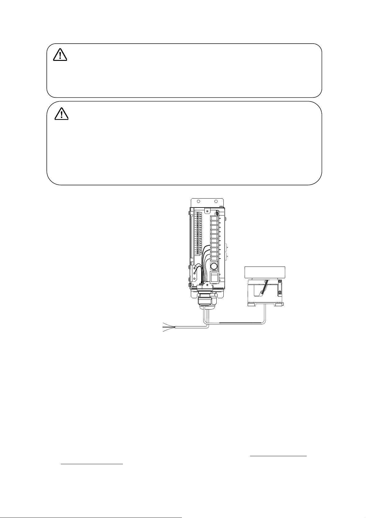
(Note 1) When the bowl feeder is used in assembly with another device or the like, do not turn On-Off
the “On-Off”switch on the primary side of the controller but make use of the external control
signal input terminal.
(Note 2) Ensure that the power connection work is executed by electrical engineers. When
modification or change of wiring is intended, be sure to refer to the Instruction Manual for the
bowl feeder controller.
(Note 3) Where a bowl is provided with an alignment mechanism and an instruction mark is located
around the speed control knob of the controller, operate the machine with the speed control
knob position adjusted to the marking.
(Note 4) When extension of the load cable is intended by your company, ensure the extension length of
10 m max. in use of a cable of 2.5 mm2min. in size. In addition, conduct the protective
continuity test to check that the machine is grounded appropriately.
(Note 5) For details of required operation of the controller to be used, refer to the Instruction Manual
for the bowl feeder controller.
8. Inspection and Adjustment
(1) Inspection and adjustment of leaf spring
[1] Acceptable maximum amplitude of leaf spring
To prevent break of the leaf springs, operate the machine at amplitude lower than shown in the
following table.
If the machine should be operated at higher amplitude, the leaf springs may break at an early date.
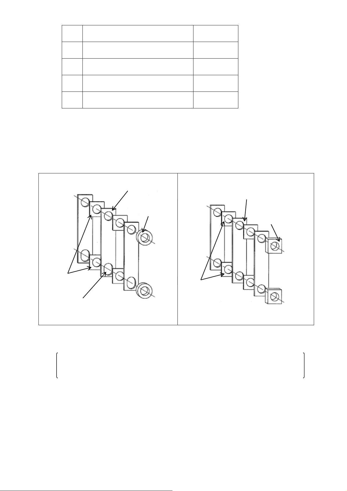
When measuring the amplitude, be sure to attach the supplied amplitude marks as shown below
and total the readings of upper and lower amplitudes.
Type㺃
size
Leaf spring part No.
Amplitude
(upper area + lower area)
K10
K-PLS2-35 5
(K-PLS2-35 4)
0.6 mm
(0.8 mm)
K14
K-PLS2-50
9
(K-PLS2-50 7)
1.1 mm
(1.4 mm)
K16
K-PLS2-67 12-1
1.2 mm
K20
K-PLS2-116 35
-1
K-PLS2-116 20-2
1.3 mm
2.3 mm
(Note) When a recommended speed is designated by
NTN
, adjust the volume position to the
recommended scale.
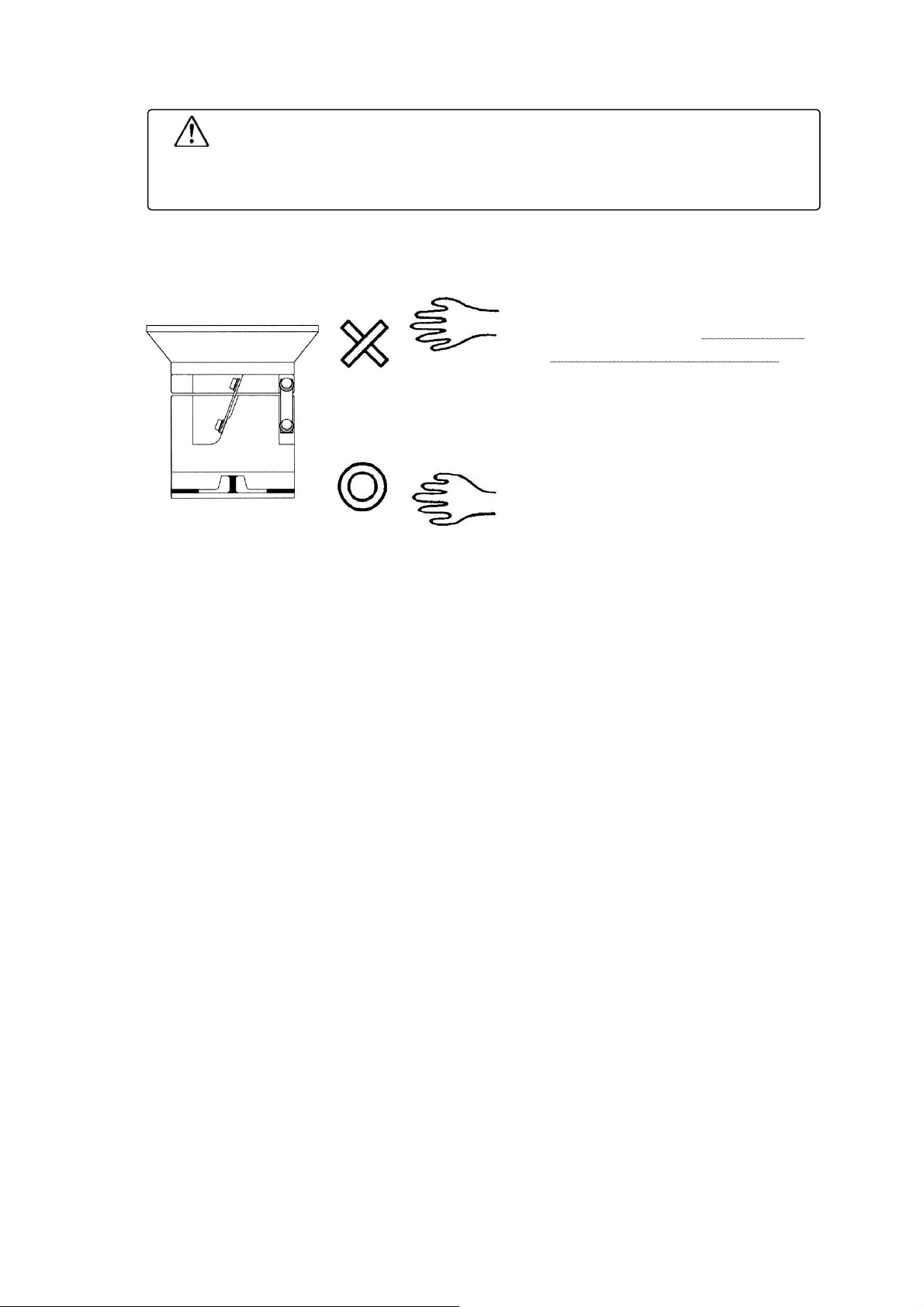
[2] Caution in attaching and detaching leaf spring
When attaching and detaching the leaf spring, be sure to
complete one unit before moving to the next unit. Do not
loosen all the units at the same time.
a) Change the bolt length according to the increase or
decrease in the number of springs on assumption that
required bolt bite length (Dimension L includes the
dimension on the upper vibrator side) is at least 2 times
as large as screw diameter (at least 8 mm for K10).
Tighten bolts securely while referring to the tightening
torques shown below as standard values.
Amplitude mark
(upper vibrator)
Amplitude mark
(lower vibrator)

- 9 -
Type㺃
size
Bolt used
Tightening
torque
K10
Washer based hexagon socket head cap screw M5
(strength division of 10.9 or higher)
About 8.8 N㺃
m
{90 kgf
㺃
m}
K14
Washer based hexagon socket head cap screw M6
(strength division of 10.9 or higher)
About
14.7 N㺃
m
{150 kgf
㺃
m}
K16
Washer based hexagon socket head cap screw M8
(strength division of 10.9 or higher)
About
34.3 N㺃
m
{350 kgf
㺃
m}
K20
Hexagon socket head cap screw M12
(strength division of 10.9 or higher)
About
117.6 N㺃
m
{1200 kgf
㺃
m}
(b) Assemble the leaf springs and spacers after applying grease or rust preventive oil between them.
(
(Note 1)
Be careful not to include dirt, chips and others between leaf springs.
(Note 2)
As to K14, K16 and K20, press the leaf springs against the body side and align their end
faces before assembly.
K10
Align oblong holes on the bottom side.
K14,K16, K20
[3] Retightening
Check the leaf spring tap bolts (or nuts) after actual run for about 40 hours, and retighten the bolts.
When the bolts have been tightened to normal torque, there hardly is allowance for additional
tightening, but consider this requirement as retightening to ensure comfortable fitting of leaf
springs.
[4]Correction of fatigue
When the SPEED ADJ. volume come to be used at the max. position at all times, add one or two
pieces of leaf springs to any one place of the leaf spring unit.
Oblong holes
Spacer
Leaf spring
Spacer
Leaf spring
Spring weight
washer
Spring weight
washer

- 10 -
Even if the leaf spring mounting bolts are fastened normally, the spring constant of spring itself
may reduce owing to repetitive stress resulting from vibration after the machine is run for 40 to
100 hours.As a result, the amplitude may decrease negligibly.
[5]Replacement of leaf spring
Replacement of all leaf springs is recommended after run of the machine for 1 year on the basis of
8-hour run a day as a guideline.
If the amplitude cannot be recovered even after correction of set in fatigue in the paragraph մ
above, it is considered that the leaf springs have reached the end of life. 100% replacement of
leaf springs is recommended.
(Note) When new leaf springs are required, place an order with us while referring to the part No. of
the leaf spring shown in Section 10 “Specifications”.
(2) Check and adjustment of clearance in magnet
The clearance between the magnet and the moving iron core (K10 is upper vibration) is set to a value
shown in the following table when the body is shipped from NTN. But, since minimization of the
clearance is advisable to the extent not to allow contact of them with each other at the occasion of
maximum amplitude, check the clearance from time to time to keep a proper value.
In a much dusty environment, such dust may stick to the magnet and the movable iron core solidly to
narrow the clearance, possibly resulting in generation of unusual noise. Conduct check to remove
dust and others periodically.
<Adjusting method>
Insert a clearance gauge of 0.1 t to 0.6 t into the
clearance in the magnet as shown, and adjust the
clearance at the oblong hole in the leaf spring in
the case of K10 and the circle hole in the leaf
spring in the case of K14, K16 or K20.
Check after adjustment of the clearance that the
clearance between the top vibrator and the bottom
vibrator is uniform in the forward/backward and
right/left directions.
Type/Drive
method
Magnet clearance (mm)
In
shipment
Maximum
K10 (Full wave)
K14 (Full wave)
K16 (Full wave)
K20 (Full wave)
0.3
K20 (Half wave)
0.6
Clearance
Clearance gauge
CAUTION
When the machine is operated with the clearance in
the magnet
increased by 20% in
excess of the maximum value shown above, the
magnet may burn. Check the
clearance in the magnet from time to time to keep a proper value.

- 11 -
(3) Change of power frequency
The power frequency of the NTN bowl feeder is adjusted in conformance to the value applicable
to the area where it is used or the preset frequency for the controller. Accordingly, normal
vibrations cannot be ensured, if the power frequency or the preset frequency for the controller as
the output frequency for driving should change. When change of the power frequency is intended,
strictly observe the procedure described below.
(Note) Where the output frequency for driving is set on a variable frequency controller, change of
settings is not required, even if the power frequency (50 Hz 60 Hz) is changed.
[1] Change of number of leaf springs
50 Hz 60 Hz: Increase the number of leaf springs by about 40%.
60 Hz 50 Hz: Decrease the number of leaf springs by about 30%.
<For information: How to check the number of leaf springs for surplus or shortage>
Check according to the following method whether the number of
leaf springs currently mounted is excessive or short for the bowl
and the alignment mechanism used.
Slightly loosen the leaf spring mounting bolt located at one place
while allowing continuous vibrations of the machine, and check
the amplitude.
•Amplitude increased. Number of leaf springs is too large.
•Amplitude decreased. Number of leaf springs is too small or
proper.
Optimum number of leaf springs is that sufficient amplitude is
ensured and that the amplitude decreases when the bolt is
loosened.
[2] Changeover of frequency in controller
Set the frequency as shown below. For details, refer to the Instruction Manual for individual
controllers.
Power source frequency
In the case of 50HzIn the case of 60Hz
Setting of DIP switch
by K-EGA57.
6:
21
6:
2))
6:
2))
6:
21
㻞 㻟
㻻㻺
㻝㻞㻟 㻢㻣㻤㻠㻡
㻻㻺
㻻㻲㻲
㻞 㻟
㻻㻺
㻝㻞㻟 㻢㻣㻤㻠㻡
㻻㻺
㻻㻲㻲

- 12 -
Iron scale or
the like
Magnet
Magnet clearance
9. Troubleshooting
If any trouble should be found, check the following points:
(1) No vibration at all
In this case, conduct checking after dividing the trouble contents into those of the mechanical
system and the electric system.
Turn ON the POWER switch, and insert an iron piece into the clearance in the magnet as shown
below.
[1] When the iron piece is attracted strongly during vibration
Electric system is normal. Accordingly, the cause
of the trouble lies in either setting of the number of
leaf springs of the bowl feeder or wrong
designation of the power frequency.
[2] When the iron piece is not attracted at all
Trouble of electric system including controller and
magnet. However, if the controller is equipped with
a sensor, it is possible that the detection head
detects a workpiece. It is not a trouble. Align optical
axis or recheck proximity distance, etc.
Further, check the following points for electric system for safety:
a) Power supply is connected properly. (See the Section 7 “Wiring and Operating Methods”.)
b) No melting of controller fuse and no working of overcurrent protective function
c) Shorting of the controller external control signal input terminals. Closing of the terminals
according to external control signal (refer to the Controller Instruction Manual.)
(2) Vibration is
available but
amplitude is
insufficient
[1] Imperfect power source (such as 100 V connection in spite of 200 V
specification)
[2]
Leaf spring mounting bolt is loosened.
[3]
Tightening bolt of bowl etc. is loosened.
[4]
Magnet clearance is too large.
[5]
Omission of removal of fixtures used for transportation
(3) Amplitude is
decreasing
during use
[1] Leaf spring is fatigued.
[2] Leaf spring mounting bolt is loosened.
[3] Leaf spring is damaged, and rust is found.
[4] Foreign substance is caught in the magnet clearance.
[5] Bowl tightening bolt is loosened.
(4) Unusual
metallic
noise
[1] Contact of magnet with moving iron core due to narrow magnet clearance
or inclusion of foreign matter in magnet clearance
[2]
Over-
amplitude
[3]Non-removal of transportation fixtures
When you inform NTN of trouble condition with unknown cause, let them know the detail as far as
possible with reference to the above so that they can take a measure as soon as possible.

- 13 -
10. Specifications
K K 10
R
L
1 1
Voltage㺃drive system
(1 : Voltage 100 V [Full wave], 2 : Voltage 200 V [Full wave])
Design change code
Feed direction (R : Clockwise, L : counterclockwise)
Body size
Body type
Product No.
K-K10R
L1
K-K10R
L2
K-K14R
L1
K-K14R
L2
Supply voltage (V)
100
200
100
200
Consumption current (A)
0.3
0.15
0.7
0.35
Dissipation power (VA)
30
30
70
70
Drive method
Full wave
Frequency (times/min)
6000 (50 Hz), 7200 (60 Hz)
Spring angle ()
20r
Max.
loading
mass (kg)
(work + bowl mass)
1.5 2.5
Magnet par
t No.
(No. of magnet used)
K-PMG-111
-1
(1 piece)
K-PMG
-
121
-1
(1 piece)
K-PMG-211
-1
(1 piece)
K-PMG-221
-1
(1 piece)
Cable size
length
(from center)
1.0 mm21.1 m
Leaf spring fitting (places)
4
Standard No. of leaf
springs set
4 pieces 4 places = 16 pieces
6 pieces 4
places = 24
pieces
Leaf spring part
No.
(material)
K-PLS2-35 5 (Steel) K-PLS2-50 9 (Steel)
Leaf spring dim. (mm)
Length (hole pitch)
Width
Thickness
46 (35) 10 0.5 64 (50) 14 0.9
Leaf spring fixing bolt
strength division
12.9
Leaf spring tightening
torque
8.8 Nxm (90 kgfxcm) 14.7 Nxm (150 kgfxcm)
Outside coating color
Black/silver
Mass (kg)
3.6
10.0
Note) For controllers that can apply to this machine, refer to the Catalog and the Controller Instruction
Manual.

- 14 -
K K 16
R
L
3 1
Voltage㺃drive system
(1 : Voltage 100 V [Full wave], 2 : Voltage 200 V [Full wave])
Design change code
Feed direction (R : Clockwise, L : counterclockwise)
Body size
Body type
Product No.
K-K16R
L31
K-K16R
L32
Supply voltage (V)
100
200
Consumption current (A)
1.8
0.3
Dissipation power (VA)
180
60
Drive method
Full wave
Frequency (times/min)
6000 (50 Hz), 7200 (60 Hz)
Spring angle ()
20r
Max.
loading
mass (kg)
(work + bowl mass)
7.5
Magnet par
t No.
(No. of magnet used)
K-PMG-311-3
(1 piece)
K-PMG-321-4
(1 piece)
Cable size
length
(from center)
1.0 mm21.1 m
Leaf spring fitting (places)
4
Standard No. of leaf
springs set
7
pieces 4 places = 28 pieces
Leaf spring part No.
(material)
K-PLS2-67 12-1 (Steel)
Leaf spring dim. (mm)
Length (hole pitch)
Width
Thickness
87 (67) 20 1.2
Leaf spring fixing bolt
strength division
12.9
Leaf spring tightening
torque
34.3 Nxm (350 kgfxcm)
Outside coating color
Black/silver
Mass (kg)
20
Note) For controllers that can apply to this machine, refer to the Catalog and the Controller Instruction
Manual.

- 15 -
K K 20
R
L
1 1
Voltage㺃drive system
(1 : Voltage 100 V [Full wave], 2 : Voltage 200 V [Full wave])
(3 : Voltage 100 V [Half wave], 4 : Voltage 200 V [Full wave])
Design change code
Feed direction (R : Clockwise, L : counterclockwise)
Body size
Body type
Product No.
K-K20R
L1
K-K20R
L2
K-K20R
L3
K-K20R
L4
Supply voltage (V)
100
200
100
200
Consumption current (A)
2.5
1.5
2.0
1.0
Dissipation power (VA)
250
300
200
200
Drive method
Full wave
Half wave
Frequency (times/min)
6000 (50 Hz), 7200 (60 Hz)
3000 (50 Hz), 3600 (60 Hz)
Spring angle ()
15
r
25
r
Max.
loading
mass (kg)
(work + bowl mass)
10
Magnet par
t No.
(No. of magnet used)
K-PMG-411
-1
(1 piece)
K-PMG-421
-1
(1 piece)
K-PMG-411
-2
(1 piece)
K-PMG-421
-2
(1 piece)
Cable size
length
(from center)
1.5 mm21.1 m
Leaf spring fitting (places)
3
Standard No. of leaf
springs set
4
pieces 3 places = 12 pieces
3 pieces 3 places = 9 pieces
Leaf spring part No.
(material)
K-PLS2-116 35-1 (Steel)
K-PLS2-116 20-2 (Steel)
Leaf spring dim. (mm)
Length (hole pitch)
Width
Thickness
136 (116) 35
3.5
136 (116) 35 2.0 (Z spring)
Leaf spring fixing bolt
strength division
12.9
Leaf spring tightening
torque
117.6 Nxm (1200 kgfx
cm)
Outside coating color
Black/silver
Mass (kg)
35
Note) For controllers that can apply to this machine, refer to the Catalog and the Controller Instruction
Manual.

- 16 -
About NTN Parts Feeder Shipping Warranty Card
A shipping warranty card is attached to this product. Be sure to receive the card at the occasion of your
purchase of the product.
The warranty card assures free repair of the product in accordance with conditions specified in the card.
You are requested to keep the card after reading the descriptions given therein carefully.
•The Instruction Manual is subject to change without prior notice for functional improvement or other
purposes.
Revised : Oct. 1, 2013
NTN
Technical Service Corporation
Precision Equipment Division
1578 Higashi-Kaizuka, Iwata, Shizuoka 438-8510 Japan
PHONE:81-0538-37-8104 FAX:81-0538-37-8128
All rights reserved.
NTN
Technical Service Corporation 2013
This manual suits for next models
3
Table of contents
Other NTN Industrial Equipment manuals