MENU
12/24
TIME
C/F
FLOOR/AMBIENT
TILE/LAMINATE
HISTORY
EXIT
NUHEAT ELEMENT
QUICK START GUIDE
GUIDE DE DÉMARRAGE
RAPIDE -
NUHEAT ELEMENT
CLASSIFICATION
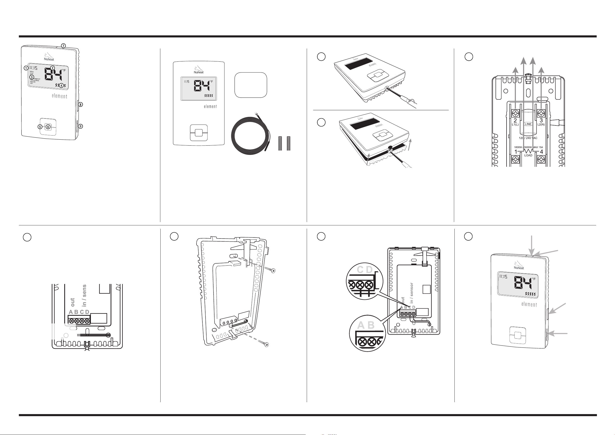
The product is a Class II device (enhanced insulation) and must be
connected to the following leads:
Phase L1 (L) 120 V, Phase L2 (N) 0/120 V, Max. load 15 A (resistive load)
The terminals are suitable for field wiring cables of 12 to 22 AWG.
Heating element in accordance with the supply voltage.
TECHNICAL DATA
Supply ...................................................................120/240 Vac 50/60 Hz
Load ......................................................................max. 15 A (resistive load)
Power ...................................................................1800 W at 120 Vac
..............................................................................3120 W at 208 Vac
..............................................................................3600 W at 240 Vac
GFCI ......................................................................Class A (5 mA trip level)
Temperature range ..............................................+5 to +40°C, +41 to
+104°F
Amb. temp. range ................................................0 to +25°C, +32 to +77°F
Construction of Control: Electronic room thermostat for regulating
electrical underfloor heating.
Method of Mounting Control: Independently mounted control for flush
mounting
Type of Action:.......................................................Type 2.B.
Rated Impulse Voltage:.........................................2500 V
Control Pollution Degree:.....................................PD2
CERTIFICATION UL Listed for the US and Canada
According to the following standards:
Thermostat: UL 60730-1
UL 60730-2-9
CSA E60730-1:13
CSA E60730-2-9
UL file number: E157297
GFCI: UL 943 4th ed.
CSA C22.2 No. 144.1-06
Patent pending
CLASSIFICATION
Le produit est un dispositif de classe II (isolation améliorée) et doit être
branché aux broches suivantes :
Phase L1 (L) 120 V, Phase L2 (N) 0/120 V, Charge max. 15 A (charge
résistive)
Les bornes sont appropriées aux fils de câblage de 12 à 22 AWG.
L’élément chauffant est conforme à la tension d’alimentation.
FICHE TECHNIQUE
Alimentation ............................................ 120/240 Vac 50/60 Hz
Charge ..................................................... max. 15 A (charge résistive)
Puissance ................................................ 1800 W à 120 Vac
.................................................................. 3120 W à 208 Vac
.................................................................. 3600 W à 240 Vac
GFCI.......................................................... Classe A (seuil de
déclenchement 5 mA)
Plage de température ............................. +5 à +40 °C, +41 à +104 °F
Plage de temp. amb. ............................... 0 à +25 °C, +32 à +77 °F
Construction du dispositif de commande : Thermostat électronique de
pièce pour réguler un plancher
chauffant électrique.
Méthode de montage du dispositif : Dispositif de commande à montage
indépendant pour montage encastré
Action de type : ........................................ Type 2.B.
Tension assignée de choc : ..................... 2500 V
Milieu de pollution du dispositif de commande : DP2
CERTIFICATION : Homologué UL au Canada et aux États-Unis
Selon les normes suivantes :
Thermostat : UL 60730-1
UL 60730-2-9
CSA E60730-1:13
CSA E60730-2-9
Numéro de dossier UL : EE157297
GFCI : UL 943 4eéd.
CSA C22.2 No. 144.1-06
Brevet en instance
BASIC OPERATION
Increasing/Decreasing the Temperature
By default, the thermostat displays the CURRENT temperature. Press the Up/Down button ONCE to
activate the backlight. Press the Up/Down button again to adjust the TARGET temperature. The screen
will display the TARGET temperature for five seconds.
Setting the Time
1. Press the Center button TWICE to access the Menu.
2. Using the Up/Down buttons, go to 12/24 and press the Center button.
3. Select the time format (12-hour clock or 24-hour clock) and press the Center button.
4. Using the Up/Down buttons, go to TIME and press the Center button.
5. Set the hour and press the Center button.
6. Set the minutes and press the Center button.
7. Using the Up/Down buttons, go to EXIT and press the Center button.
Changing Temperature Unit
1. Press the Center button TWICE to access the Menu.
2. Using the Up/Down buttons, go to C/F and press the Center button.
3. Select the temperature unit (Celsius or Fahrenheit) and press the Center button.
4. Using the Up/Down buttons, go to EXIT and press the Center button.
Changing Temperature Control Setting
1. Press the Center button TWICE to access the Menu.
2. Using the Up/Down buttons, go to FLOOR/ROOM and press the Center button.
3. Select the temperature control setting and press the Center button.
4. Using the Up/Down buttons, go to EXIT and press the Center button.
OPÉRATION DE BASE
Augmenter/Réduire la température
Par défaut, le thermostat affiche la température ACTUELLE. Appuyer sur les boutons Up/Down* UNE
FOIS pour allumer le panneau lumineux. Appuyer sur les boutons Up/Down de nouveau pour régler la
température CIBLE. L’écran affichera la température CIBLE pendant 5 secondes.
Régler l’heure
1. Appuyer sur le bouton centre DEUX FOIS pour accéder au menu.
2. À l’aide des boutons Up/Down, aller à 12/24 et appuyer sur le bouton centre.
3. Sélectionner l’affichage de l’heure (format horaire 12 ou 24 heures), puis appuyer sur le bouton
centre.
4. À l’aide des boutons Up/Down, aller à HEURE et appuyer sur le bouton centre.
5. Sélectionner l’heure et appuyer sur le bouton centre.
6. Sélectionner les minutes et appuyer sur le bouton centre.
7. À l’aide des boutons Up/Down, aller à QUITTER et appuyer sur le bouton centre.
Changer l’unité de température
1. Appuyer sur le bouton centre DEUX FOIS pour accéder au menu.
2. À l’aide des boutons Up/Down, aller à C/F et appuyer sur le bouton centre.
3. Sélectionner l’unité de température (Celcius ou Fahrenheit) et appuyer sur le bouton centre.
4. À l’aide des boutons Up/Down, aller à QUITTER et appuyer sur le bouton centre.
Changer les réglages de température
1. Appuyer sur le bouton centre DEUX FOIS pour accéder au menu.
2. À l’aide des boutons Up/Down, aller à C/F et appuyer sur le bouton centre.
3. Sélectionner l’unité de température (Celcius ou Fahrenheit) et appuyer sur le bouton centre.
4. À l’aide des boutons Up/Down, aller à QUITTER et appuyer sur le bouton centre.
BASIC OPERATION/OPÉRATION DE BASE
For detailed information regarding Nuheat thermostat warranty, please visit www.nuheat.com./Pour plus de détails sur la garantie du thermostat Nuheat, consulter www.nuheat.com.
Changing Floor Type (not selectable if Temperature Control setting is set to ROOM
– refer to ‘Changing Temperature Control Setting’ section)
1. Press the Center button TWICE to access the Menu.
2. Using the Up/Down buttons, go to TILE/LAMINATE and press the Center button.
A. TILE - floor temperature will be limited to 104°F/40°C
B. LAMINATE - floor temperature will be limited to 82°F/28°C.
3. Select the floor type and press the Center button.
4. Using the Up/Down buttons, go to EXIT and press the Center button.
Monitoring Usage
1. Press the Center button TWICE to access the Menu.
2. Using the Up/Down buttons, go to HISTORY and press the Center button.
A. The display will show the number of HOURS (denoted by the ‘h’ on the right side of the screen) the
floor heating system has been on in the past 7 days. When done, press the Center button.
3. Using the Up/Down buttons, go to EXIT and press the Center button.
Troubleshooting
E02 - This error message indicates a missing or damaged floor sensor. Contact your installer to verify the floor sensor
and connections or contact Nuheat Customer Care Team at 1.800.778.WARM (9276).
Changer le type de plancher (seulement possible si ROOM est sélectionné – se reporter
à la section Changer les réglages de température)
1. Appuyer sur le bouton centre DEUX FOIS pour accéder au menu.
2. À l’aide des boutons Up/Down, aller à CARRELAGE/LAMINÉ et appuyer sur le bouton centre.
A. CARRELAGE – la température du plancher sera limitée à 104 °F/40 °C
B. LAMINÉ – la température du plancher sera limitée à 82 °F/28 °C
3. Sélectionner le type de plancher et appuyer sur le bouton centre.
4. À l’aide des boutons Up/Down, aller à QUITTER et appuyer sur le bouton centre.
Contrôler l’utilisation
1. Appuyer sur le bouton centre DEUX FOIS pour accéder au menu.
2. À l’aide des boutons Up/Down, aller à HISTORIQUE et appuyer sur le bouton centre.
A. L’affichage indiquera le nombre d’HEURES (indiqué par la lettre h du côté droit de
l’écran) que le système de chauffage était en marche au cours des 7 derniers jours.
3. À l’aide des boutons Up/Down, aller à QUITTER et appuyer sur le bouton centre.
Dépannage
E02 - Ce message d’erreur indique un capteur de plancher manquant ou endommagé. Communiquer avec l’installateur
pour vérifier le capteur de plancher et les connexions ou communiquer avec l’équipe du Service à la clientèle Nuheat au
1.800.778.9276.
Temperature Control Setting Description
Floor (Default) Thermostat controls the floor temperature.
Room
Thermostat controls the room air temperature.
This setting is useful if the floor temperature sensor is damaged
or not installed.
Floor/Room
Advanced users only—the thermostat controls the room air
temperature and limits the floor temperature to 104°F/40°C for Tile
and 82°F/28°C for Laminate.
Réglage de la température Description
Floor (par défaut) Le thermostat contrôle la température du plancher.
Room
Le thermostat contrôle la température de la pièce.
Ce réglage est utile si le capteur de température du plancher est
endommagé ou n’est pas installé.
Floor/Room
Pour utilisateurs chevronnés seulement – le thermostat contrôle la
température de l’air ambiant et maintient la température du plancher
à 104 °F/40 °C pour plancher en carrelages et 82 °F/28 °C pour
plancher en laminé.
*Augmenter/Réduire
WARNINGS:
To avoid electric shock, disconnect the heating system power
supply at the main panel before installation and maintenance of
the thermostat. Keep thermostat air vents clean and free from
obstruction. This thermostat is an electrical product and must be
installed in compliance with the National and/or Local Electrical
Code. Installation must be performed by qualified personnel where
required by law.
AVERTISSEMENTS :
Pour éviter une décharge électrique, coupez l’alimentation du
système de chauffage au panneau de distribution avant l’installation
et/ou l’entretien du thermostat. Gardez toujours les évents du
thermostat propres pour éviter les obstructions. Ce thermostat
est un produit électrique et doit être installé conformément aux
codes nationaux et locaux de l’électricité. Lorsque la loi l’exige, le
thermostat doit être installé par du personnel qualifié.
NORTH AMERICA AMÉRIQUE DU NORD
Tel. Numéro sans frais : +1.800.778.9276
Fax Télécopieur : +1.604.529.4404
www.nuheat.com
res.customercare@pentair.com
Pentair and Nuheat are owned by Pentair or its global affiliates. All
other trademarks are the property of their respective owners. Pentair
reserves the right to change specifications without prior notice.
Pentair et Nuheat sont la propriété de Pentair et ses filiales
mondiales. Toutes les autres marques de commerce appartiennent à
leurs propriétaires respectifs. Pentair se réserve le droit de changer
les spécifications sans préavis.
© 2018 Pentair.
Nuheat-IM-H59311-ElementThermostatProgCOM-EN 18/01THERMAL MANAGEMENT
Version 67288G Updated December 2017