Nu-Heat NTG5110 User manual

NTG5110 & NTG5220 400-115-006-E 10/11/06 1/3
Nuheat’s NTG5110 & NTG5220 programmable thermostats can be
used to control the ambient air temperature or floor temperature. You
can select among the following temperature control modes:
Memory Backup:
In the event of a power failure, an internal circuit will maintain the pro-
gramming and time. However, the time will have to be re-set if the
power failure exceeds 6 hours.
Set the time using the Hour and Min buttons.
Set the day using the Day button.
Press Mode/Ret to exit.
The Comfort , Economy and Vacation settings respectively
represent the temperatures that you wish to have during the day ( ),
at night or while you are away at work ( ), or while you are away for
an extended period ( ).
This thermostat is pre-programmed with the following default Com-
fort, Economy and Vacation setpoints.
If the default temperature settings suit your personal preferences,
skip the following section.
To Modify the Default Setpoints:
To modify the Comfort temperature, select the desired
temperature using the buttons and hold the button until
the icon is displayed (app. 3 seconds).
To modify the Economy temperature, select the desired temper-
ature using the buttons and hold the button until the icon
is displayed (app. 3 seconds).
To modify the Vacation temperature, select the desired tempera-
ture using the buttons and hold the button until the
icon is displayed (app. 3 seconds).
Press the Mode/Ret button to exit this function and return to the
normal operating mode.
Description
1.
A mode: controls the ambient air temperature
F mode: controls the floor temperature using an
external temperature sensor
AF mode: controls the ambient air temperature
maintains the floor temperature within desired
limits using an external temperature sensor
Operating Modes
2.
MANUAL
Allows you to manually adjust the temperature set-
point.
To activate this mode, press Mode/Ret to dis-
play the icon.
Set the desired temperature using or
select one of the pre-programmed settings
( , or ).
AUTO
Executes the default schedule or your own pro-
gramming.
Use this mode to maximize energy savings. To
activate it, press Mode/Ret to display the icon.
The or icon indicates which temperature set-
ting is used. Also, the icon of the period number
will be shown. (i.e. )
Power On switch /
reset GFCI
Temperature
adjustment
Set programming
Select Operating
Mode / Return
Temperature
Operating mode icons
Period number
Comfort setpoint
Time and day
Heating indicator
Backlight button
Erase programming
Comfort, Economy
and Vacation icons
Appears when the
setpoint is displayed
Temperature control
mode icons
Ground fault
indicator
Lights up display, automatically turns off after 12 seconds
Set day
Set timeEconomy setpoint
Vacation setpoint
Time and Day Adjustment
3.
Setpoint Configuration
4.
Icon Setpoint F mode A/AF mode
Comfort 88 °F (31 °C) 70 °F (21 °C)
Economy 73 °F (23 °C) 63 °F (17 °C)
Vacation 50 °F (10 °C) 50 °F (10 °C)
NTG5110 & NTG5220
Homeowner’s Guide
Programmable Thermostats

NTG5110 & NTG5220 400-115-006-E 10/11/06 2/3
This thermostat is pre-programmed with the following default sched-
ule:
It applies to people who wake up at 6:00 AM, leave for work by 9:00
AM, return home for 5:00 PM and go to sleep at 11:00 PM.
If the pre-programmed schedule fits your lifestyle, skip the following
section.
First, program your schedule. You can program 4 different periods for
each day of the week. For each day, enter:
Press Pgm to access the programming mode. Period 1 is
displayed ( ).
Press Day to select the day to be programmed (hold for
3 seconds to select all days of the week).
NOTE: It is faster to program the same schedule for the entire week,
then modify the exception days (i.e. Saturday and Sunday).
Press Hour and Min to program the start time, OR
Press Clear to clear a time entry.
Press Pgm to select the next period.
Repeat steps 3 and 4 for remaining periods.
When you have completed your programming, press
Mode/Ret to exit the programming mode.
Programming Example:
This example applies to people who are home during the week.
• Comfort period from 6:00 AM to 11:00 PM (Period 1)
• Economy period from 11:00 PM to 6:00 AM (Period 4)
• Identical schedule for all days of the week.
Press Pgm to access the programming mode.
Period 1 is displayed ( ).
Press and hold Day for 3 seconds to select every day
of the week.
Press Hour to enter 6:00 AM for Period 1.
Press Pgm to select Period 2 ( ) and press Clear to delete
the time entry (- - : - -).
Press Pgm to select Period 3 ( ) and press Clear to delete
the time entry (- - : - -).
Press Pgm to select Period 4 ( ) and press Hour to enter
11:00 PM.
When you have completed your programming, press
Mode/Ret to exit the programming mode.
To modify the Saturday and Sunday Schedules:
When making modifications, make sure you are in the right period.
For example, if you are modifying the time for the time you wake up,
make sure you are in Period 1.
Press Pgm to select Period 1 ( ).
Press Day to select SA (Saturday).
Press Hour and Min to enter the time you wake up on week-
ends.
Press Pgm to select Period 4 ( ).
Press Hour and Min to enter the time you go to sleep on week-
ends.
Repeat above steps for Sunday (SU).
Press Mode/Ret to exit programming mode.
NOTE: To avoid damaging your floor, follow your floor supplier’s rec-
ommendations regarding the minimum and maximum floor tempera-
ture limits.
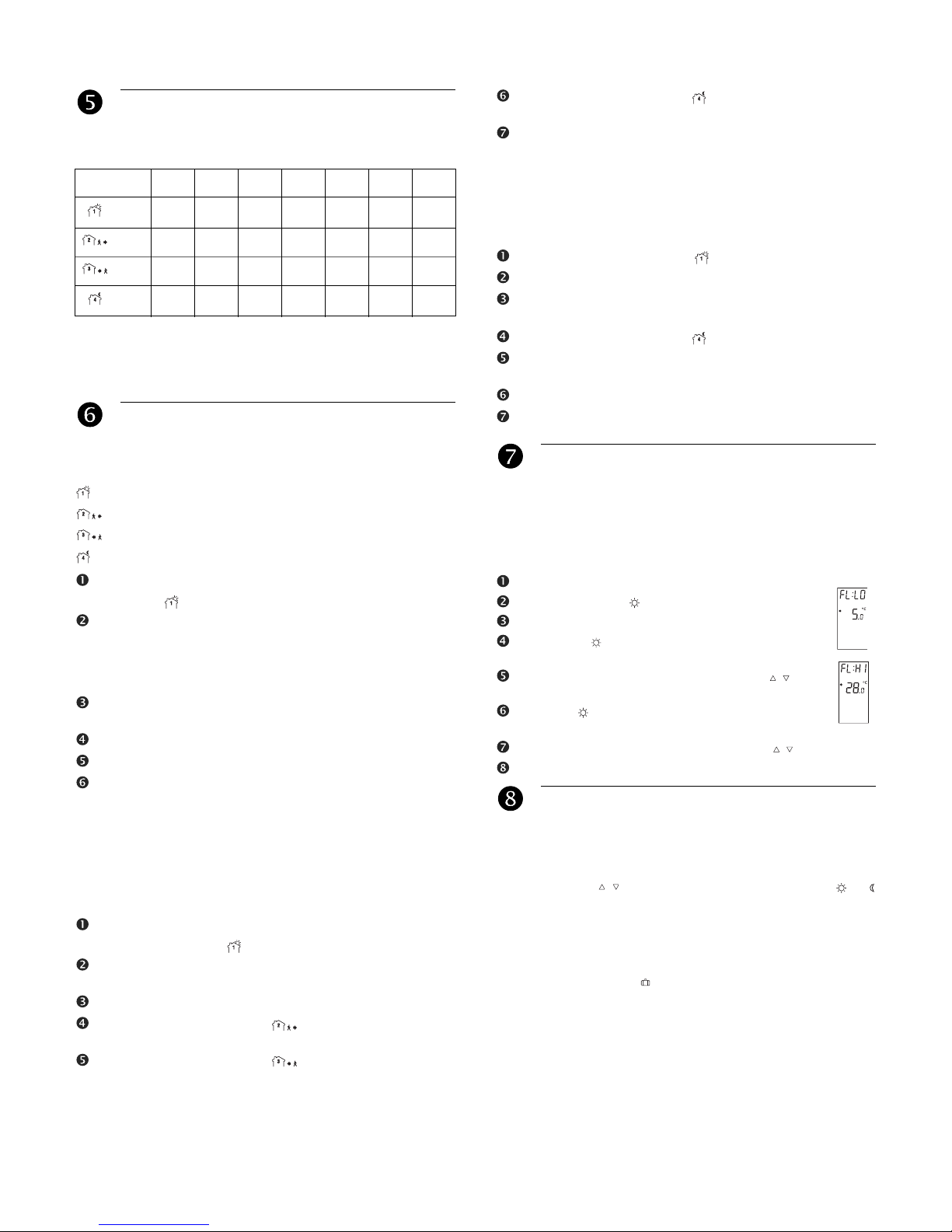
The minimum and maximum floor temperature limits are 5 °C (41 °F)
and 28 °C (82 °F) by default. To modify these limits, proceed as fol-
lows:
Switch the thermostat to Standby.
Press and hold the button.
Switch the thermostat back to On.
Release the button when the minimum temperature
limit (FL:LO) appears.
Set the minimum temperature limit using the
buttons.
Press the button to display the maximum
temperature limit (FL:HI).
Set the maximum temperature limit using the buttons.
Press Mode/Ret to exit.
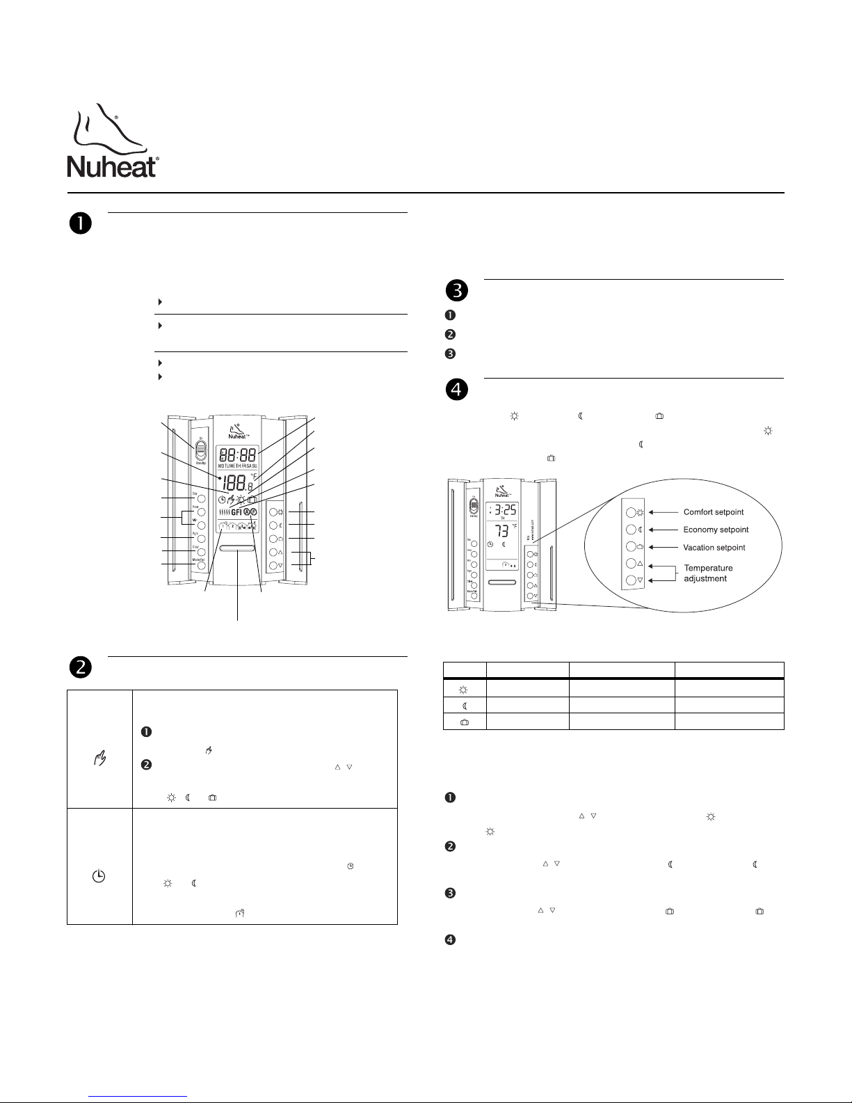
Temporary or Permanent Temperature Bypass:
This operation allows you to temporarily modify the floor temperature
while you are in the Automatic mode.
• Simply press to select the desired temperature, or or
button to select the Comfort or Economy settings you have pro-
grammed.
This temperature will be maintained until the beginning of the
next programmed schedule.
• You can also switch to the Vacation setting for a prolonged
absence by pressing . In that case, the temperature bypass is
permanent.
To return to the normal operating mode, press Mode/Ret.
If you wish to immediately return to the programmed settings, press
Mode/Ret.
Default Schedule
5.
Periods MON TUE WED THU FRI SAT SUN
88°F 6 AM 6 AM 6 AM 6 AM 6 AM 6 AM 6 AM
73°F 9 AM 9 AM 9 AM 9 AM 9 AM --:-- --:--
88°F 5 PM 5 PM 5 PM 5 PM 5 PM --:-- --:--
73°F 11 PM 11 PM 11 PM 11 PM 11 PM 11 PM 11 PM
Modify the Default Schedule
6.
Time you wake up (Period 1)
Time you leave for work (Period 2)
Time you return home (Period 3)
Time you go to bed (Period 4)
Floor Temperature Limits (AF mode only)
7.
Special Features
8.

NTG5110 & NTG5220 400-115-006-E 10/11/06 3/3
Early Start Function:
This thermostat is equipped with a function that enables it to calcu-
late the optimum time to start the heating system to achieve the
desired temperature setting by the programmed time.
It could start the heating system as early as 6 hours prior if neces-
sary. Every day, the thermostat will automatically re-evaluate how
early to start heating, based on the previous day’s performance.
The switch on the back of the thermostat is factory-set to Early Start
ON. To disable this function, see the Switch Selection section.
Daylight Savings Time:
The thermostat can automatically re-adjust its time at Daylight Sav-
ings Time changeover.
Year 2006: When this function is enabled (On), the thermostat
switches to Daylight Savings Time on the first Sunday of April and to
normal time on the last Sunday of October.
Year 2007 and on: When this function is enabled (On), the thermo-
stat switches to Daylight Savings Time on the second Sunday of
March and to normal time on the first Sunday of November.
NOTE: The function is disabled (default setting) when the clock loses
its setting.
Press the Day button (3 seconds) until DLS appears
on the screen.
Press the to toggle between On (enabled) and Off
(disabled).
Press the Day button briefly. The year setting is dis-
played.
Press the to set the current year.
Press the Day button briefly. The month setting is dis-
played.
Press the to set the current month.
Press the Day button briefly. The date setting is dis-
played.
Press the to set the current date.
Press Mode/Ret to exit.
The thermostat can be configured with the following settings:
To Modify the Default Settings:
Locate the screw at bottom of thermostat. Unscrew.
Remove thermostat faceplate.
Locate the switches at the back of the faceplate. Set the
switches to your preferences.
Put the faceplate back on the thermostat.
Secure the thermostat with the screw.
Display range: 32 °F to 158 °F (0 °C to 70 °C)
Ambient setpoint range (A/AF models)
: 40 °F - 86 °F (5 °C to 30 °C)
Floor setpoint range (F model): 40 °F - 104 °F (5 °C to 40 °C)
Floor limit range (AF model): 40 °F - 104 °F (5 °C to 40 °C)
NUHEAT INDUSTRIES ONE (1) YEAR LIMITED WARRANTY
This product is guaranteed against workmanship defects for a
one-year period following the initial date of purchase. During this
period, NUHEAT will repair or replace, at our option and without
charge, any defective product which has been used under normal
conditions.
The warranty does not cover delivery costs and does not apply to
products poorly installed or randomly damaged following installation.
This warranty cancels and replaces any other manufacturer's
express or implied warranty as well as any other company commit-
ment.
NUHEAT cannot be held liable for related or random damages follow-
ing the installation of this product. The defective product as well as
the purchase invoice must be returned to the place of purchase or
mailed, prepaid and insured, to the following address:
Switch Selection
9.
# FUNCTION UP DN
1 Temperature format display °F °C
2 Early Start ON OFF
3Temperature control mode a
a. To select the F mode, place the switch in the F position. To select the AF mode,
place the switch in the AF position and ensure that the remote temperature sensor
is connected to the thermostat. To select the A mode, place the switch in the AF
position and ensure that the remote temperature sensor is NOT connected to the
thermostat.
F AF
Factory settings
Technical Specifications
10.
Warranty
11.
NUHEAT INDUSTRIES LTD.
USA
6920 Salashan Parway
Building D-200
Ferndale, WA 98248
CANADA
1689, avenue Cliveden
Delta, BC
V3M 6V5
1 (800) 778-9276
www.nuheat.com
NUHEATTM is a registered trademark of Nuheat Industries LTD.
As an ENERGY STAR® partner,
Nuheat™ has determined that this thermostat meets
the ENERGY STAR guidelines for energy efficiency.

ELECTRICIAN’S INSTRUCTIONS
FOR MODEL NG110 (120 VAC)
INSTALLATION
This power base is designed to control electric floor-warming systems.
The resistive load must not exceed 1800 watts (NI) @ 120 VAC (15 A).
The thermostat is equipped with a Ground Fault Circuit Interrupter
(GFCI) and therefore the isolation of the line and load are required for
operation. Do not cap all the white wires together. During a ground
fault, both line and load will be cut-off. Connect thermostat as shown on
diagram.
Must be installed in accordance with national and local electrical
codes.
TURN OFF POWER TO THE HEATING SYSTEM AT THE MAIN
POWER PANEL TO AVOID ELECTRICAL SHOCK.
1Connecting wires and mounting power base
•Connect the power base
wires to the supply and load
using solderless connectors
for copper wires.
See diagram.
• Push the excess wire back
into the electrical box to
prevent interference with the
power base.
NOTE: All cables and connections must conform to the local
electrical code.
WARNING: Special CO/ALR solderless connectors must be used
when connecting with aluminum conductors.
2Connecting temperature sensor wire
• The wire must pass outside
the electrical box and follow
the wall down to the floor.
The sensing probe should be
placed in a representative
heat area for maximum
system performance.
•The sensing probe should
be centered between the
wires in the mat. The
temperature sensor wire
cannot cross any heater
wires and the sensing probe
must NOT be directly on or
adjacent to a heating wire.
• Secure the power base with the screw.
• Connect the temperature sensor wire to terminals 3 and 4 on the
power base (no polarity needs to be respected).
• Once the power base is properly installed, mount the faceplate.
14/05/03 920-112-000-00-1-A
NG110
SUPPLY
LOAD
WARRANTY
NUHEAT INDUSTRIES ONE (1) YEAR LIMITED WARRANTY
This product is guaranteed against workmanship defects for a one-year
period following the initial date of purchase. During this period,
NUHEAT will repair or replace, at our option and without charge, any
defective product which has been used under normal conditions.
The warranty does not cover delivery costs and does not apply
to products poorly installed or randomly damaged following installation.
This warranty cancels and replaces any other manufacturer's express
or implied warranty as well as any other company commitment.
NUHEAT cannot be held liable for related or random damages
following the installation of this product.
The defective product as well as the purchase invoice must be returned
to the place of purchase or mailed, prepaid and insured, to the
following address:
NUHEAT INDUSTRIES LTD.
USA CANADA
880 Grant Avenue 1689 Cliveden Avenue
Blaine, WA Delta, BC
98230 V3M 6V5
1 (800) 778-9276
www.nuheat.com
TECHNICAL SPECIFICATIONS
Model: NG110
Supply: 120 VAC, 50/60 Hz
Load: 15 A maximum
Power: 1800 watts (NI) @ 120 VAC
Ground Fault Circuit Interrupter (GFCI): Class A (5 mA)
Approvals: CSA / C,US
Storage: -4°F to 120°F (-20°C to 50°C)
NUHEAT is a registered trademark of Nuheat Industries LTD.
TM
Keep the thermostat’s air vents clean and free from
obstructions.
1 Locate the screw at the
bottom of the front module.
2 Secure the thermostat
with the screw.
3 Turn the power back on.
MOUNTING THE FACEPLATE
POWER ON
When the unit is power on for the first time,
the following appears on-screen:
Time (0:00)
Floor temperature
Manual mode icon ( )
If improperly installed, you will see the LO
or HI error message.
LO: Floor temperature is below 0°C
(32°F); or temperature probe is
defective (open) or not connected.
*If the heating indicator is also
displayed, then the relay is closed
and current is going through the load.
HI:
NT5
1-800-778-WARM
www.nuheat.com
Day
Test
Stand By
On
Hour
Min
Pgm
Clear
Mode/Ret
R
Floor temperature is above 60°C (140°F);
or temperature probe is shorted.
GFCI TEST
NT5
1-800-778-WARM
www.nuheat.com
Day
Test
Test
Stand By
On
Hour
Min
Pgm
Clear
Mode/Ret
R
1Adjust the setpoint temperature until the heating indicator ( )
appears on-screen.
2Press TEST. The test is successful if the GFCI warning light is ON
and power is cut-off. The heating indicator ( ) should still appear.
3Switch power to Standby, then reset to ON.
If test fails:
A- Verify installation.
B- Check the load wires.
C- Verify that the thermostat is in
heating mode with Heating
indicator ON.
Once you’ve identified the
problem, run the GFCI test again.

ELECTRICIAN’S INSTRUCTIONS
FOR MODEL NG220 (240 VAC)
INSTALLATION
This power base is designed to control electric floor-warming systems.
The resistive load must not exceed 3600 watts (NI) @ 240 VAC (15 A).
The thermostat is equipped with a Ground Fault Circuit Interrupter
(GFCI) and therefore the isolation of the line and load are required for
operation. During a ground fault, both line and load will be cut-off.
Connect thermostat as shown on diagram.
Must be installed in accordance with national and local electrical
codes.
TURN OFF POWER TO THE HEATING SYSTEM AT THE MAIN
POWER PANEL TO AVOID ELECTRICAL SHOCK.
1Connecting wires and mounting power base
•Connect the power base
wires to the supply and load
using solderless connectors
for copper wires.
See diagram.
• Push the excess wire back
into the electrical box to
prevent interference with the
power base.
NOTE: All cables and connections must conform to the local
electrical code.
WARNING: Special CO/ALR solderless connectors must be used
when connecting with aluminum conductors.
2Connecting temperature sensor wire
• The wire must pass outside
the electrical box and follow
the wall down to the floor.
The sensing probe should be
placed in a representative
heat area for maximum
system performance.
•The sensing probe should
be centered between the
wires in the mat. The
temperature sensor wire
cannot cross any heater
wires and the sensing probe
must NOT be directly on or
adjacent to a heating wire.
• Secure the power base with the screw.
• Connect the temperature sensor wire to terminals 3 and 4 on the
power base (no polarity needs to be respected).
• Once the power base is properly installed, mount the faceplate.
14/05/03 920-112-001-00-1-A
NG220
SUPPLY
LOAD
WARRANTY
NUHEAT INDUSTRIES ONE (1) YEAR LIMITED WARRANTY
This product is guaranteed against workmanship defects for a one-year
period following the initial date of purchase. During this period,
NUHEAT will repair or replace, at our option and without charge, any
defective product which has been used under normal conditions.
The warranty does not cover delivery costs and does not apply
to products poorly installed or randomly damaged following installation.
This warranty cancels and replaces any other manufacturer's express
or implied warranty as well as any other company commitment.
NUHEAT cannot be held liable for related or random damages
following the installation of this product.
The defective product as well as the purchase invoice must be returned
to the place of purchase or mailed, prepaid and insured, to the
following address:
NUHEAT INDUSTRIES LTD.
USA CANADA
880 Grant Avenue 1689 Cliveden Avenue
Blaine, WA Delta, BC
98230 V3M 6V5
1 (800) 778-9276
www.nuheat.com
TECHNICAL SPECIFICATIONS
Model: NG220
Supply: 240 VAC, 50/60 Hz
Load: 15 A maximum
Power: 3600 watts (NI) @ 240 VAC
Ground Fault Circuit Interrupter (GFCI): Class A (5 mA)
Approvals: CSA / C,US
Storage: -4°F to 120°F (-20°C to 50°C)
NUHEAT is a registered trademark of Nuheat Industries LTD.
TM
Keep the thermostat’s air vents clean and free from
obstructions.
1 Locate the screw at the
bottom of the front module.
2 Secure the thermostat
with the screw.
3 Turn the power back on.
MOUNTING THE FACEPLATE
POWER ON
When the unit is power on for the first time,
the following appears on-screen:
Time (0:00)
Floor temperature
Manual mode icon ( )
If improperly installed, you will see the LO
or HI error message.
LO: Floor temperature is below 0°C
(32°F); or temperature probe is
defective (open) or not connected.
*If the heating indicator is also
displayed, then the relay is closed
and current is going through the load.
HI:
NT5
1-800-778-WARM
www.nuheat.com
Day
Test
Stand By
On
Hour
Min
Pgm
Clear
Mode/Ret
R
Floor temperature is above 60°C (140°F);
or temperature probe is shorted.
GFCI TEST
NT5
1-800-778-WARM
www.nuheat.com
Day
Test
Test
Stand By
On
Hour
Min
Pgm
Clear
Mode/Ret
R
1Adjust the setpoint temperature until the heating indicator ( )
appears on-screen.
2Press TEST. The test is successful if the GFCI warning light is ON
and power is cut-off. The heating indicator ( ) should still appear.
3Switch power to Standby, then reset to ON.
If test fails:
A- Verify installation.
B- Check the load wires.
C- Verify that the thermostat is in
heating mode with Heating
indicator ON.
Once you’ve identified the
problem, run the GFCI test again.
This manual suits for next models
1
Table of contents
Other Nu-Heat Thermostat manuals

Nu-Heat
Nu-Heat HMY110 User manual

Nu-Heat
Nu-Heat TEMPO User manual

Nu-Heat
Nu-Heat NTG5110 Assembly instructions

Nu-Heat
Nu-Heat Solo User manual

Nu-Heat
Nu-Heat FTGF1P User manual

Nu-Heat
Nu-Heat Home User manual

Nu-Heat
Nu-Heat NTG5110; NTG5220 Assembly instructions

Nu-Heat
Nu-Heat SOLO User manual

Nu-Heat
Nu-Heat ELEMENT User manual

Nu-Heat
Nu-Heat neoAir User manual