Nu-Heat TEMPO User manual

Tempo 400-114-019-A 2008-11-05 1/3
The Tempo thermostat is designed to control the temperature of a
floor heating system for both 120-volt and 240-volt applications. The
thermostat can be used to control either the floor temperature or the
ambient temperature. It has a maximum load capacity of 15 A
(1800 W @ 120 VAC or 3600 W @ 240 VAC).
SUPPLIED PARTS
• One (1) thermostat
• One (1) floor temperature sensor
• Four (4) solderless connectors
• Two (2) 6-32 mounting screws
• One (1) flat-tip screwdriver
TURN OFF POWER TO THE HEATING SYSTEM AT THE MAIN POWER
PANEL TO AVOID ELECTRICAL SHOCK. THE INSTALLATION MUST
BE PERFORMED BY A QUALIFIED ELECTRICIAN.
The thermostat’s housing is not watertight. Do NOT install the
thermostat in an area where it can be exposed to water or rain.
nTo remove the thermostat faceplate, loosen the screw at the
bottom of the thermostat and lift the bottom of the faceplate
outwards towards you.
o
Connect the thermostat wires to the power supply and to the load
using solderless connectors for copper wires as shown below.
NOTE: All wires and connections must conform to the local electrical
code. This thermostat has tinned copper wires for line and load
connections. Special CO/ALR solderless connectors must be used if
these wires are to be connected to aluminium conductors.
pPull the temperature sensor wires through one of the openings
on the thermostat base and connect the wires to terminals 1 and
2 (no polarity).
• The sensor cable must not come in contact with the
electrical wires and must be routed outside the electrical
box and follow the wall down to the floor.
• Position the sensor cable such that it does not come in
contact with the floor heating wires. The sensor must be
centered between two floor heating wires for best
temperature control.
• Do NOT staple the sensor head (the plastic end) to the floor.
Doing so might damage the sensor. Any damages might not
be noticeable during testing but can become apparent
several days later.
qPush the excess length of the line voltage wires back inside the
electrical box. Install the thermostat base onto the electrical box
using the provided screws.
rSet the DIP switches (refer to section 3).
nDescription
1.
oInstallation
2.
Backlight button
(see section 4.3)
Temperature
adjustment button
On/Off switch
(see section 4.4)
Heating Intensity
indicator
(see section 4.2)
Temperature
Setpoint indicator
(see section 4.1)
Groundfaultindicator
(see section 5)
Unoccupiedmode
indicator
(see section 7.2)
GFCI test button/light
L2(N)
L1(L)
L2(N)
L1(L)
Load
Power supply
Red
Black
Red
(White)
Red
Black
Black
Black
240 V (120 V)
Red
(White)
Floor sensor
To remote control device (see section 7.2)
TEMPO
User Guide
Non-programmable Thermostat
400-114-019-A (Nuheat) ENG.fm Page 1 Wednesday, November 5, 2008 9:24 AM

Tempo 400-114-019-A 2008-11-05 2/3
sReinstall the thermostat faceplate on its base and secure it with
the screw. If there is a sticker on the screen, peel it off.
tApply power to the heating system. Verify the installation by
making sure that the heating system can be turned on or off by
increasing or decreasing the setpoint respectively.
uTest the GFCI (refer to section 5).
NOTE: Keep the thermostat's air vents clean and unobstructed at all
times.
Set the DIP switches on the back of the thermostat faceplate
according to your preference and specific application.
3.1 Temperature Unit Setting (S1)
Use the S1 switch to configure the thermostat to display the
temperature in Fahrenheit (default) or Celsius.
3.2 Temperature Control Mode Setting (S2)
Use the S2 switch to configure the thermostat to control the floor tem-
perature, ambient air temperature, or a combination of ambient air
and floor temperature.
4.1 Temperature Display and Setting
The thermostat displays the current (measured) temperature. To view
the desired temperature, press either of the buttons. The desired
temperature is displayed for 5 seconds.
To set a new temperature, press one of the buttons repeatedly
until the desired temperature is displayed. To scroll faster, press and
hold the button.
4.2 Heat Intensity Indicator ( )
The heat intensity indicator is a graphic representation of how long
the floor heating system is turned on compared to how long it is
turned off in order to reach and maintain the set temperature. The
more bars means the longer the floor heating system is turned on.
4.3 Backlight button
The display illuminates for 5 seconds when the backlight button is
pressed and for 10 seconds when either of the buttons is
pressed.
4.4 On/Off Switch
Use Off mode to turn off the floor heating system. This mode can be
used when you are away for an extended period of time such as a
vacation or during warmer months. In Off Mode, the thermostat
screen becomes blank but the settings are not erased.
This thermostat has a built-in GFCI (Ground Fault Circuit Interrupter).
The GFCI protects against risk of electrocution caused by a current
leakage. If the leakage current exceeds 5 mA, the GFCI will automat-
ically trigger, thus cutting power to the floor heating system. To indi-
cate the fault, the TEST button at the top of the thermostat will
illuminate (red) and GFI will appear on the screen.
If the TEST button illuminates and GFI appears on the screen during
normal operation, check if the fault has been caused by an external
interference such as a halogen light or an electric motor. In this case,
reset and test the GFCI. However, if the fault occurs again for
unknown reasons, cut power to the floor heating system from the
main electrical panel and have the installation verified by an
electrician.
WARNING: The GFCI does not protect against electrical shocks
resulting from contact with both conductor wires.
5.1 GFCI Reset
To reset the GFCI, switch the thermostat to Off and back to On. The
TEST button light will go off and GFI will disappear from the screen.
5.2 GFCI Test
To ensure the GFCI is always in working order, test it once the ther-
mostat is installed and test it every month thereafter.
nIncrease the temperature sufficiently to start heating.
oWait for about 5 seconds until the heat intensity indicator ( )
appears on the screen.
pPress the TEST button at the top of the thermostat.
• If the TEST button does NOT illuminate, the test has failed.
Cut power to the heating system at the main electrical panel,
have an electrician verify the installation and, if necessary,
replace the thermostat.
pDIP Switch Settings
3.
F: To select the F mode. In this mode, the thermostat controls the
floor temperature.
AF: To select the A or AF mode (default setting).
NOTE: If the S2 switch is placed on AF and the floor sensor is
connected, the thermostat will operate in AF mode. If the S2
switch is placed on AF and the floor sensor is NOT connected,
the thermostat will operate in A mode.
In A mode, the thermostat controls the ambient air
temperature. This setting is useful if the floor temperature
sensor is damaged or not installed.
In AF mode, the thermostat controls the ambient air
temperature and maintains the floor temperature within
desired limits. This control is for advanced users only
(refer to section 7.1).
Faceplate
Power base
Air vents
Air vents
qBasic Operation
4.
rGFCI
5.
400-114-019-A (Nuheat) ENG.fm Page 2 Wednesday, November 5, 2008 9:24 AM

Tempo 400-114-019-A 2008-11-05 3/3
• If the TEST button illuminates, continue to step 4.
qSwitch the thermostat to Off then back to On.
• If the TEST button light goes off, the test has passed. Set the
thermostat back to the desired temperature and ignore the
remaining steps. The test is now completed.
• If the TEST button light remains on, the test has failed. Con-
tinue to step 5.
rSwitch the circuit breaker (at the service panel) of the heating
system to off then back to on.
sRepeat the test. If the test fails again, cut power to the heating
system at the main electrical panel, have an electrician verify the
installation and, if necessary, replace the thermostat.
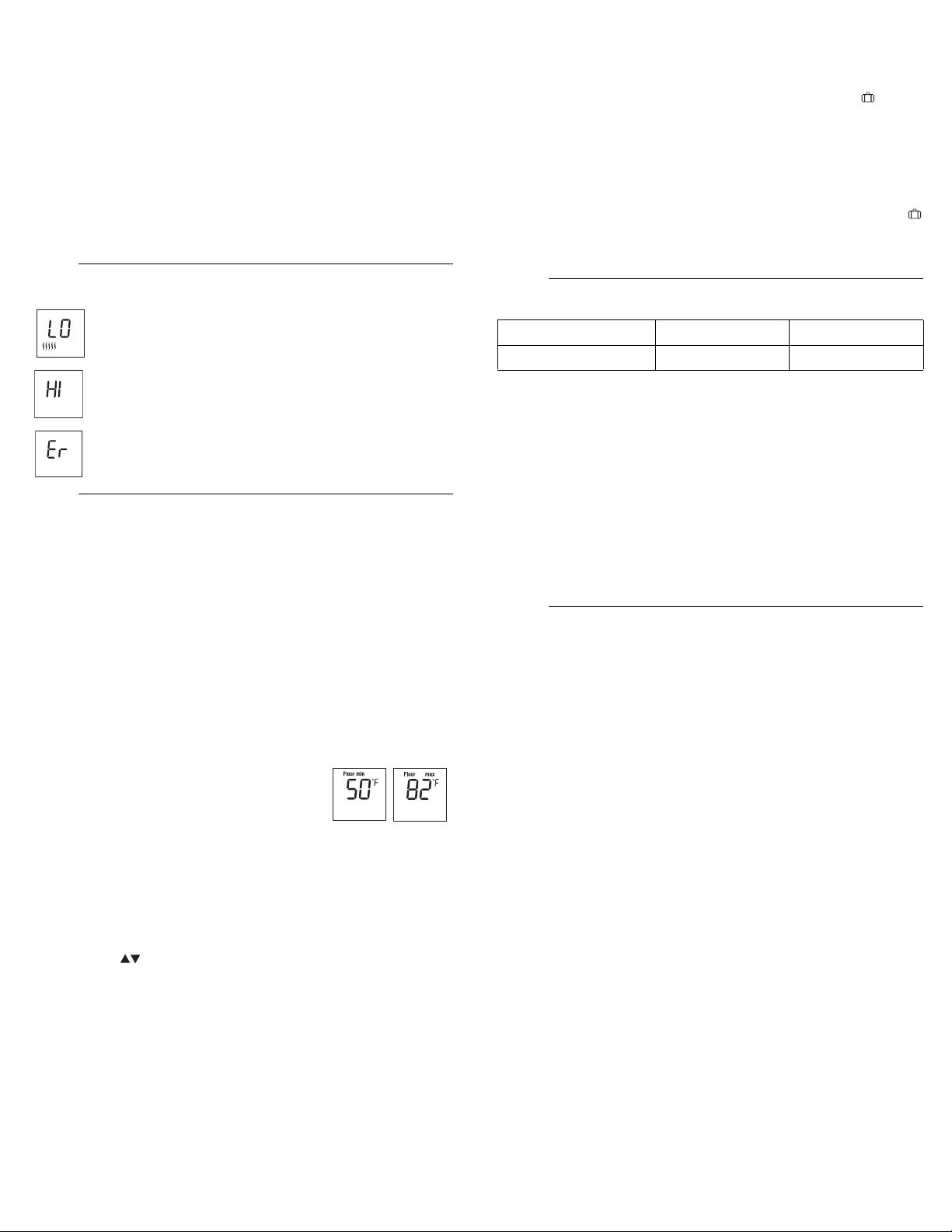
The measured temperature is below the thermostat’s dis-
play range. Heating is activated.
The measured temperature is above the thermostat’s dis-
play range. Heating is deactivated.
Verify the thermostat and sensor connections.
7.1 Floor Limit Settings
You can set the minimum and maximum temperature that your floor
can reach. These settings are available only if the temperature
control mode setting is at AF (refer to section 3.2).
NOTE: The desired ambient temperature might not be attainable if
the maximum floor temperature is set too low.
The thermostat generally turns heating On or Off to control the ambi-
ent temperature. However, if the floor temperature drops below the
set minimum floor temperature limit or rises above the maximum
limit, the thermostat will turn heating On or Off respectively, regard-
less of the ambient temperature, to maintain the floor temperature
within the desired limits.
The minimum and maximum floor temperature
limits are factory-set at 50 °F (10 °C) and 82 °F
(28 °C) respectively. To modify the limits, pro-
ceed as follows:
nSwitch the thermostat to Off.
oWhile pressing any button, switch the thermostat back to On to
access the floor temperature limit settings.
pPress the Backlight button briefly to switch between minimum
and maximum floor temperature settings.
qPress the buttons to set the desired limit.
rPress the Backlight button for 3 seconds to save your modifica-
tions. After the data are saved, the thermostat displays the cur-
rent temperature or “– –”.
NOTE: Your modifications are automatically saved if no button is
pressed for 60 seconds.
7.2 Unoccupied Mode
The thermostat can be connected to any other remote control device
equipped with a dry contact. When the contact closes, the Unoccu-
pied Mode is activated and the Unoccupied Mode icon is dis-
played. In this mode, the thermostat lowers its setpoint by 7 °F (3.5
°C) and all temperature adjustments are blocked except for tempo-
rary bypass.
Temporary Bypass
You can temporarily bypass the Unoccupied Mode by pressing the
backlight button. During the bypass, the Unoccupied Mode icon
flashes. The bypass is automatically cancelled after 2 hours or if the
backlight button is pressed again.
Display range - F mode: 32 °F to 140 °F (0 °C to 60 °C)
- AF mode: 32 °F to 122 °F (0 °C to 50 °C)
Setpoint range - F mode: 40 °F to 104 °F (5 °C to 40 °C)
- A/AF mode: 40 °F to 86 °F (5 °C to 30 °C)
Floor limit range (AF mode): 40 °F to 104 °F (5 °C to 40 °C)
Resolution: ± 1.0 °F (0.5 °C)
Operating temperature: 32 °F to 122 °F (0 °C to 50 °C)
Storage temperature: -4 °F to 122 °F (-20 °C to 50 °C)
Control cycle: 15 minutes
GFCI rating: 5 mA
Certification: c CSA us
NUHEAT INDUSTRIES THREE (3) YEAR LIMITED WARRANTY
This product is guaranteed against workmanship defects for a three-
year period following the initial date of purchase. During this period,
NUHEAT will repair or replace, at our option and without charge, any
defective product which has been used under normal conditions.
The warranty does not cover delivery costs and does not apply to
products poorly installed or randomly damaged before, during or after
installation. This warranty cancels and replaces any other
manufacturer's express or implied warranty as well as any other
company commitment.
NUHEAT cannot be held liable for related or random damages
before, during or after the installation of this product. The defective
product as well as the purchase invoice must be returned to the place
of purchase or mailed, prepaid and insured, to the following address:
sError Messages
6.
tAdvanced Operations
7.
vTechnical Specifications
8.
Supply 120 VAC, 60 Hz 240 VAC, 60 Hz
Maximum load 15 A (1800 W) 15 A (3600 W)
;Warranty
9.
NUHEAT INDUSTRIES LTD.
USA
6920 Salashan Parkway
Building D-200
Ferndale, WA 98248
CANADA
1689 Cliveden Avenue
Delta, BC
V3M 6V5
1 (800) 778-9276
www.nuheat.com
NUHEAT®is a registered trademark of Nuheat Industries LTD.
400-114-019-A (Nuheat) ENG.fm Page 3 Wednesday, November 5, 2008 9:24 AM
Table of contents
Other Nu-Heat Thermostat manuals

Nu-Heat
Nu-Heat FTGF1P User manual

Nu-Heat
Nu-Heat NTG5110 Assembly instructions

Nu-Heat
Nu-Heat NTG5110 User manual

Nu-Heat
Nu-Heat NTG5110 Assembly instructions

Nu-Heat
Nu-Heat Home User manual

Nu-Heat
Nu-Heat neoAir User manual

Nu-Heat
Nu-Heat NTG5110; NTG5220 Assembly instructions

Nu-Heat
Nu-Heat SOLO User manual

Nu-Heat
Nu-Heat Element User manual

Nu-Heat
Nu-Heat NTG5220 Assembly instructions
Popular Thermostat manuals by other brands

S+S Regeltechnik
S+S Regeltechnik HYGRASGARD RFTF-Modbus Operating Instructions, Mounting & Installation

Honeywell
Honeywell FocusPRO TH5220D operating manual

AMG
AMG Insta-Therm instruction manual

Pro1 Technologies
Pro1 Technologies T771 Operation manual

Sencor
Sencor SDC 1200 user manual

Vimar
Vimar 01911 User quick guide