NuAire Smart S Instruction Manual

Installation
and Maintenance
Smart ‘S’
Twin Fan Control System
Used with Quietwin fans
NuAire Limited
Western Industrial Estate
Caerphilly, Mid Glamorgan CF83 1XH
United Kingdom
Telephone 01222 885911
Facsimile No. 01222 887033
Email: info @ nuaire. co.uk Leaflet No. 670963
FEBRUARY 1999
Introduction
Note:
This information is general and the specific fan
Installation & Maintenance leaflet supplied with each
Quietwin unit should be referred to when setting up and
commissioning.
If required, replacement leaflets for any Quietwin unit
are available on request from the NuAire Technical
Library Tel: 01222 858231
The NuAire Smart ‘S’ Twinfan Control system brings a
totally new concept to twinfan control technology. Low voltage
circuitry and wiring is employed between the fan and the plug
in sensors and remote controls.
The low voltage 4 -core connecting cables can be installed
without the use of expensive and unsightly housing conduits.
The twinfan is fitted with an integral control module which is
connected via low voltage cables to the sensors and remote con-
trols selected. All the mains supply and switching is housed in
the control module located at the Quietwin fan unit.
Quietwin fans with the Smart ‘S’ control option are available in
models suitable for internal (QTI & QTE) and external
(QTE& QTR) applications.
Internal QTI units have their Smart control module mounted
on the exterior sidewall of the casing.
Note that for weathering purposes the exterior (QTE & QTR)
units have the main Smart control module mounted internally
but feature a small exterior ‘commissioning’ box located on the
outside of the case to allow speed and run on time etc. to be
adjusted without removing the fans top cover.
Smart systems can be as simple or as comprehensive as the
customer wishes to suit your specific application. Our Controls
Application Service is ready to advise on your enquiry.
QUIETWIN WARRANTY
(Smart Controls)
Contents Page
Introduction 1
Smart control wiring to twinfan 2
Control module input connections 3
Commissioning 3
DIL switch settings 4
Adding sensors etc 4
Certification 5
1
Controls Application Service (CAS)
A team of Engineers and technicians is available to provide
pre and post order support.
We are on hand to provide help and advice from the most
basic use of any NuAire equipment to the more complex
applications, maximising on the versatility of our SMART
and NetLink control products.
Telephone: 01222 858585
Facsimile: 01222 858586
The 12 year warranty starts from the
date of delivery and includes parts
and labour for the first year. The
labour element is subject to full,
free and safe access to the equipment
as recommended by the CDM
regulations. The remaining 11 years
covers replacement parts only.
Year
Warranty
Year
Warranty
12
*12 Year Warranty (UK only)
* Only available on Quietwin when used with Smart
ControllinkedtoPIRSensors.Installationmustberegistered
with NuAire by completing the form provided in the fan unit
Installation & Maintenance leaflet.
Your Quietwin fan Installation & Maintenance leaflet
incorporates a warranty registration form.
Please fill in the form and return to NuAire Service
Department at the address below.
Western Industrial Estate,
Caerphilly, Mid Glam CF83 1XH
United Kingdom.
Tel: 01222 885911 Fax: 01222 887033,
Email: [email protected]
controls

INPUT 4 INPUT 3 INPUT 2 INPUT 1
RD
YL
GN
BL
RD
YL
GN
BL
N L OP CL RET OP CL RET SL FAIL
MAINS DAMPER 1 DAMPER 2 SW FAIL
LIVE SW
Volt Free
Contacts for
fail indication
240v live from light switch
(fan operates when live)
240v live to close
240v live to open
240v live to close
240v live to open
240v
mains
supply
Remote fail
sensor input
Sensor input
Sensor input
Master on/off
control input
Step button
Fan 1
Fan 2
OFF
AUTO
Speed
Run on
NOT USED
Fuse (control)
Fuse (fans)
Fuse (dampers)
DIL switches
(used to tailor
smart twin
operation)
Damper switch conn.
Remove links when
using dampers fitted
with limit switches
Optional
Sensors &
Timeclocks
etc. plug in
here
Step Button manually
steps through functions
Speed
Adjustment Run on
Adjustment
(see commissioning procedure)
Smart ‘S’ TWINFAN CONTROL Installation and Maintenance
2
Smart Control wiring to Twinfan
Figure 2 above shows the inside of the case mounted Smart Control
Module. All sensors and user controls / timeclock etc are ‘plugged in’ to
the control module circuit board. Terminal connection strip is located
on the right of the board. Note the mains connection terminals.
230v Mains
to Twinfan
Smart Control
module
Connecting unit to the mains 230v supply
Remove the control module cover (4 nylon fixings) Unscrew and
remove the aluminium terminal cover plate, Feed the mains
cable through the rubber grommet and connect your 230v supply
to the terminals marked ‘MAINS’ (See fig. 2).
Timeclock
ON/OFF
Code:
ST-TC
Manual
User
Control
ON/OFF
Code: ST-MAN
MK Adaptor plate
Code: MK-ADAPTOR
P.I.R.
Occupancy
Sensor
Code: ST-PIR
Up to four devices
can directly "plug in"
to the Smart Control
Extract from
toilet '2'
(e.g. MALE)
Extract from
toilet '1'
(e.g. FEMALE)
Humidity
Sensor
Code:
ST-HUM
Sensor
Guard
Junction
Box
Code: ST-JB
Audio / Visual
Fail Indicator
Code: ST-AVI
To up to six
additional sensors
(if required)
Airflow Direction Box
Code: ST-ADB
Smart Twinfan
(typical)
12458
9
10
11
3
7
6
MK Box
(not supplied)
Control
BMS System
interface
Code: ST-BMS
To B.M.S.
230v mains supply
COMPREHENSIVE
SMART SYSTEM
Fig. 3. Quietwin system showing additional options. QTI fan illustrated.
Fig. 2. Control module
connection details
Fig. 1. Control module location on a QTI
internal use Quietwin
Options
List of available sensors, user controls and
ancillaries for “S" option users with a refer-
ence to corresponding information leaflets
PIR Occupancy sensor, code: ST-PIR
(Leaflet No: 670864)
Humidity sensor, code:ST-HUM
(Leaflet No: 670865)
Audio / visual fail indicator, code:ST-AVI
(Leaflet No: 670877)
Timeclock on / off, code: ST-TC
(Leaflet No: 670866)
Manual user control, code ST-MAN
(Leaflet No: refer to Nuaire)
Junction Box, code: ST-JB
(Leaflet No: refer to Nuaire)
Sensor guard, code: refer to Nuaire
(Leaflet No: refer to Nuaire)
MK Adaptor plate, code:: MK ADAPTOR
(Leaflet No: refer to Nuaire)
BMS Interface, code:ST-BMS
(Leaflet No: 6708697)
Airflow direction box, code: ST-ADB
(Leaflet No: refer to Nuaire)
Low voltage comms cable 10m length
(Leaflet No: refer to Nuaire)
1
2
3
4
5
6
7
8
9
10
11

Smart ‘S’ TWINFAN CONTROL Installation and Maintenance
3
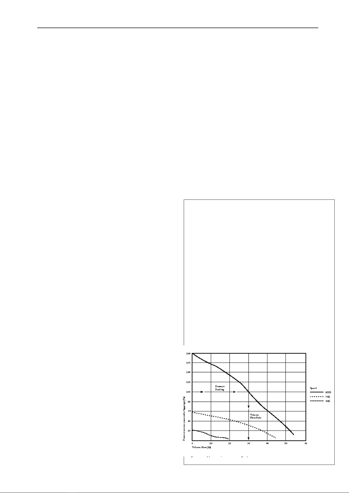
Fig. 4. A typical Quietwin graph
Commissioning Procedure (see fig. 2).
1. Switch on the supply to the QTI Quietwin fan.
2. Locate the control module panel Care must be taken if
the module has any covering panels removed as live
230v incoming supply terminals may be exposed.
Note covers MUST be properly replaced when commission
ing has been completed.
3. Wait approximately 60 seconds for the system to complete
its self test’
4. Press the step sequencing button several times until only
the ‘FAN 1’ light is illuminated and the ‘AUTO’ light is
off. (See detail of control panel Fig. 2).
5. Connect a manometer across the tappings provided on the
outside of the fan casing. Reading the manometer and using
the graph, determine the airflow. The fan is factory set at
full speed. Using the rotary graduated control,reduce the
speed to the desired setting (may require a screwdriver).
NOTE: allow 30 seconds for the fan to reach the set speed.
6. Set the Run on timer control. (Adjustable 5-60 min).
(See detail of control panel Fig. 2).
7. Press the step button through the sequence until ‘AUTO’
light shows.
COMMISSIONING IS NOW COMPLETE.
Using the graphs
(SPECIFIC GRAPHS FOR YOUR
QUIETWIN FAN ARE SHOWN IN THE
FAN INSTALLATION & MAINTENANCE
LEAFLET).
The graphs are designed to assist you in establishing an AIR
VOLUME FLOW RATE for your fan installation.
The curves shown indicate performance at 100%, 75% and 50%.
Assuming that the ventilation system is installed and the fan is
connected to all ductwork. Connect a manometer across the
tappings provided on the outside of the fan unit casing.
The fan is factory set for full speed. With the fan operating at this
full speed (100%) take a pressure reading in Pa from the
manometer. Refer to the relevant graph for your size of unit and
with your Pa figure, read across the graph to where the line
intersects the 100% curve.
Drop a line vertically down from this point and the air volume
flow is indicated on the base line of the graph.
See the fan Installation & Maintenance leaflet supplied.
Using the Step button (see fig 2).
Refer to the label on the controls inside cover for more guidance.
Pressing the step button will sequence through the options and
change the modes as follows:
1. FAN 1 in manual mode (used for commissioning)
2. FAN 2 in manual mode (used for commissioning)
3. SYSTEM OFF
4. SYSTEM IN AUTOMATIC (normal selection)
To clear a fail, press the STEP button until the fail has cleared.
IMPORTANT After commissioning, press the STEP but-
ton through until AUTO is illuminated.
System is now in automatic mode.
EXTERNAL USE QUIETWINS WITH THE SMART
CONTROL OPTION ARE PROVIDED WITH A COM-
MISSIONING BOX ON THE OUTSIDE OF THE CASE
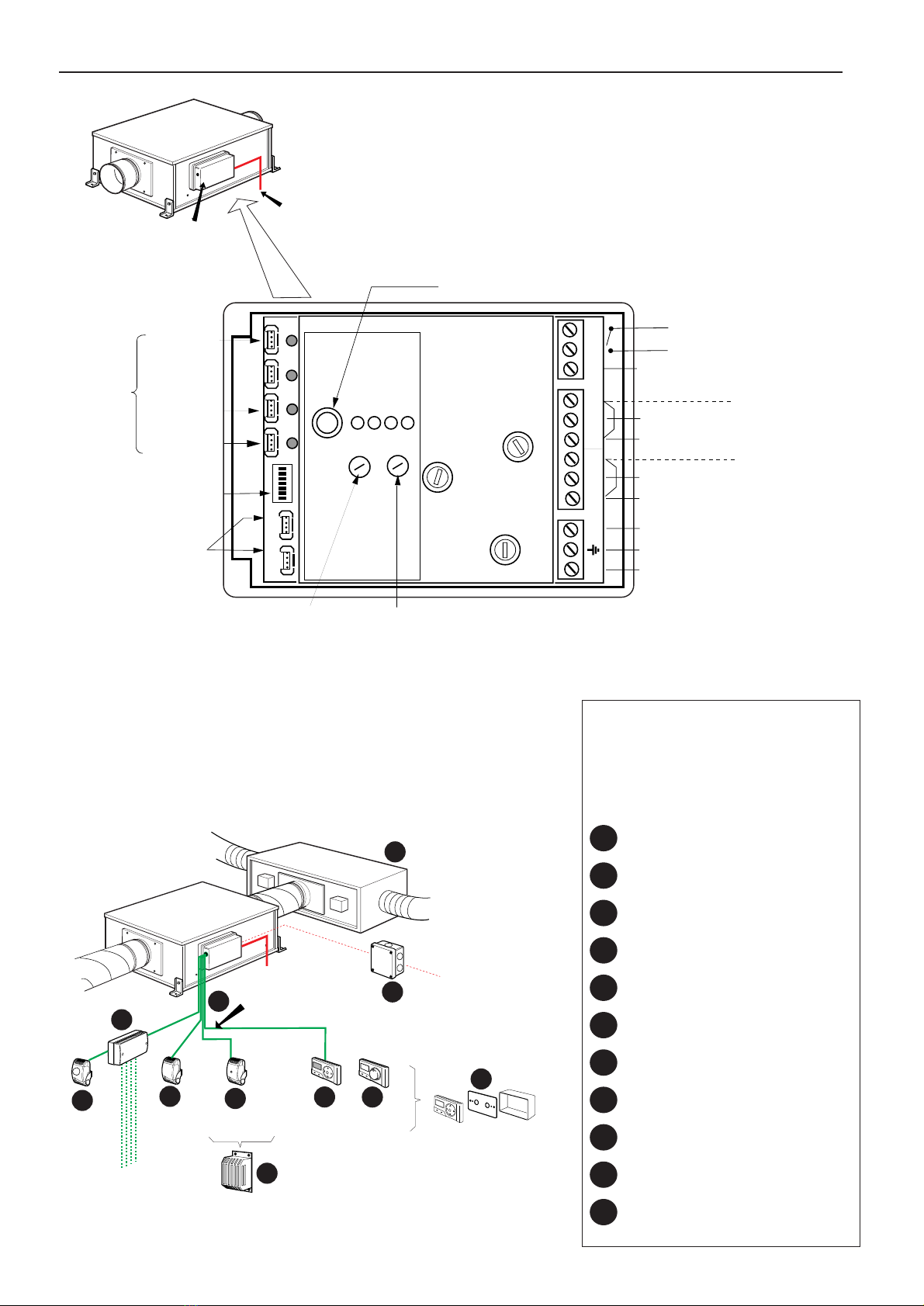
The main control module is inside the fan (See fig 5).
Control Module Connections /Inputs and
their uses (see fig 2)
SENSOR INPUT 1:
This is the Master on/off control input and is usually ‘linked out’
with a special plug unless:
A Timeclock can be connected into this input e.g. ST-TC
During ON times the unit is allowed to operate.
During OFF times the unit is off- zero duty.
Note: The ST-TC Timeclock must always be plugged into the fan
mounted control module NOT into a ST-JB junction box.
SENSOR INPUTS 2, 3 & 4
Any sensor can be connected to these inputs to allow activation
of the unit. If any of these inputs is activated, the unit will run at
the maximum set duty. These sensors include ST-PIR,
ST-HUM, ST-TEMP.
Note: Additional sensors may be added by using an ST-JB Junction Box.
SWITCH LIVE terminals
This acts just like the sensor inputs 2,3,4. If 230v ac is detected
on the SW - Live terminals, the unit will run at the max. set duty
DAMPER terminals (2 sets)
When the fan is running at full duty, both these damper connec-
tions will be activated. i.e. power will be available on the OP
terminals of the damper connections. The fan will not go to full
duty until the RET terminals have 230v ac (Limit Switch).
FAILURE RELAY
This relay is normally closed when there are no faults. When
faults occur this relay will open and break the circuit. This
method of operation allows all types of failure to be detected for
example ‘Power failed’, ‘Fan/s fail.
This connection is a volt free switch. it can handle power up to
5A (230v) and is fused for protection.
NO FAULT: The volt free switch is closed i.e. the two
terminals are connected.
FAN FAULT: The volt free switch is opened. i.e. the two
terminals are disconnected.

Smart ‘S’ TWINFAN CONTROL Installation and Maintenance
4
1 2 3 4 5 6 7 8
ON
OFF
1 2 3 4 5 6 7 8
ON
OFF
1 2 3 4 5 6 7 8
ON
OFF
1 2 3 4 5 6 7 8
ON
OFF
1 2 3 4 5 6 7 8
ON
OFF
30% TRICKLE SPEED
40% TRICKLE SPEED
50% TRICKLE SPEED
NO TRICKLE SPEED
AIRFLOW DIRECTION
BOX FITTED
Smart Twinfan DIL switch settings
(see fig 2).
The Smart Twins operation can be individually tailored to suit
your own particular application.
A label is attached to the inside of the control module cover
detailing the various switch functions.
Refer also to switch settings shown opposite.
DEFAULT MODE:
The fan runs in trickle mode until the toilet is occupied
Switch 1 & Switch 2 ..........Trickle mode and rate
Switch 3 .............................2 way Damper Box fitted
ON = Damper Box fitted (split duty system)
OFF = No Damper Box fitted
Adding Sensors & Controls
Refer to page 2 of this leaflet for a list of sensors and user
controls which are available for use with the Smart controlled
Quietwin fans.
Sensors and user controls etc are supplied complete with specif-
ic installation details.
Additional general sales information on these optional ancillaries
is shown in the NuAire ‘TWINFANS’ Sales / Technical
brochure (Leaflet No 670808) available on request from the
NuAire Technical Library Tel: 01222 858231.
QTE & QTR external use Quietwins
with SMART ‘S’ control option.
The essential control difference with these fans is that they
have the main control module inside the fan case.
A small commissioning box is provided on the outside of
the case which contains the essential commissioning control
buttons i.e. The ‘STEP’ button and the run on and speed
adjustment controls. Figure 5 shows a typical QTR
Quietwin and the details of the customers commissioning
box.
Commissioning procedure is the same as that shown on
page 3 for the internal use units.
Mains Supply
Mains Supply
and Sensor(s) to
Control Module
inside fan.
Commissioning
box on outside
of case ('S' control
external use unit only). P.I.R. Sensor
Fig. 5. Exterior commissioning control box panel.
Step button
Fan 1
Fan 2
OFF
AUTO
Speed
Run on Step Button
manually
steps through
functions
These controls
located inside
commissioning box
(External use
'S' control option
units only)
Speed
Adjustment Run on
Adjustment
(see commissioning procedure)

5
We declare that the equipment named below
conforms to the requirements of EC Council Directive
relating to Electromagnetic Compatibility
Designation of equipment :- TWINFAN CONTROL
Equipment Types :- SMART (S)
Relevant EC Council Directives :- 89/336/EEC, 92/31/EEC (EMC)
Applied Harmonised Standards :- E50081-1, EN50082-1
Basis of Self Attestation :- Quality Assurance to BS EN ISO 9001
BSI Registered Firm Certificate No. FM 149
Signature of manufacture representatives :-
Name: Position: Date:
1) C. Biggs Technical Director 2. 10. 98
2) M. Fussell Manufacturing Director 2. 10. 98
NuAire Limited,
Western Industrial Estate,
Caerphilly, Mid Glamorgan,
CF83 1XH. United Kingdom.
Telephone: 01222 885911
Fax: 01222 887033
Email: info @ nuaire. co. uk
OCTOBER 1998
DECLARATION
OF CONFORMITY

6
Technical or commercial considerations may,
from time to time, make it necessary to alter the
design, performance and dimensions of
equipment and the right is reserved to make
such changes without prior notice.
Western Industrial Estate,
Caerphilly, Mid Glam CF83 1XH
United Kingdom.
Telephone: 01222 885911
Facsimile: 01222 887033,
Email: [email protected]
Leaflet No. 670963
Smart ‘S’ TWINFAN CONTROL Installation and Maintenance
Popular Control System manuals by other brands

Volvo Penta
Volvo Penta EVC EC -C installation manual

Carefree of Colorado
Carefree of Colorado BT12 Installation

HERA
HERA POWER PACK 2500 User manual & installation guide

PPE
PPE MFT1230C instructions

Roberts Gorden
Roberts Gorden System Control HP 120 V 1 Installation & operation

IDEATEC
IDEATEC DLC4000 user guide