NuRan GSM LiteCell 1.5 User manual

GSM LiteCell 1.5
INSTALLATION GUIDE

GSM LiteCell Installation Guide Version 0.95
CONFIDENTIAL 2 of 40
Trademarks
The names of products which are found within these pages may be registered trademarks or
trademarks pertaining to their respective owners.
The symbols TM and ® have been omitted.
WARNING
Never use NuRAN products in parallel with survival or medical equipment. Not respecting this
warning excludes NuRan of any responsibility.
© 2016 NuRAN. All rights reserved.
It is strictly prohibited to reproduce or use this document, partly or in its entirety, by any means
including but not limited to graphic, electronic, and mechanical (which includes photocopy and
recording) systems without the permission of NuRAN.
To guarantee the accuracy of the information contained in this document, a very detailed review
of its contents was performed during its preparation. The information corresponds to the version
of the product manufactured before the date indicated on the cover. Differences can exist
between this document and the product if the product was modified after the release of this
document.
NuRAN reserves the right to modify, improve, or change the products describe in this document
without notice.
Revision History
Revision
Date
Comment
0.8
September 2016
Corrections to images and specs through the document
0.9
October 2016
Changed the power connector, corrected deployment kit
content and added missing information
0.91
November 2016
Added statement regarding restricted access necessisty for
installation.
0.92
March 2017
Added LED patterns in section 3.8
Changed VSWR value from TBD to <2 in table of section 2.3
0.93
March 21, 2017
Esthetics modifcations
0.94
April 13, 2017
Yannick Lebel review and merge with Jordan’s corrections.

GSM LiteCell Installation Guide Version 0.95
CONFIDENTIAL 3 of 40
0.95
April 25, 2017
Added a note about atenna separation to persons to meet RF
exposure requirements

GSM LiteCell Installation Guide Version 0.95
CONFIDENTIAL 4 of 40
Table of Content
1Introduction ....................................................................................................................7
1.1 Scope................................................................................................................................. 7
1.2 Intended Audience............................................................................................................ 7
1.3 Related Documents........................................................................................................... 7
1.4 Notices and Safety Warnings ............................................................................................ 8
1.5 Safety Precautions ............................................................................................................ 8
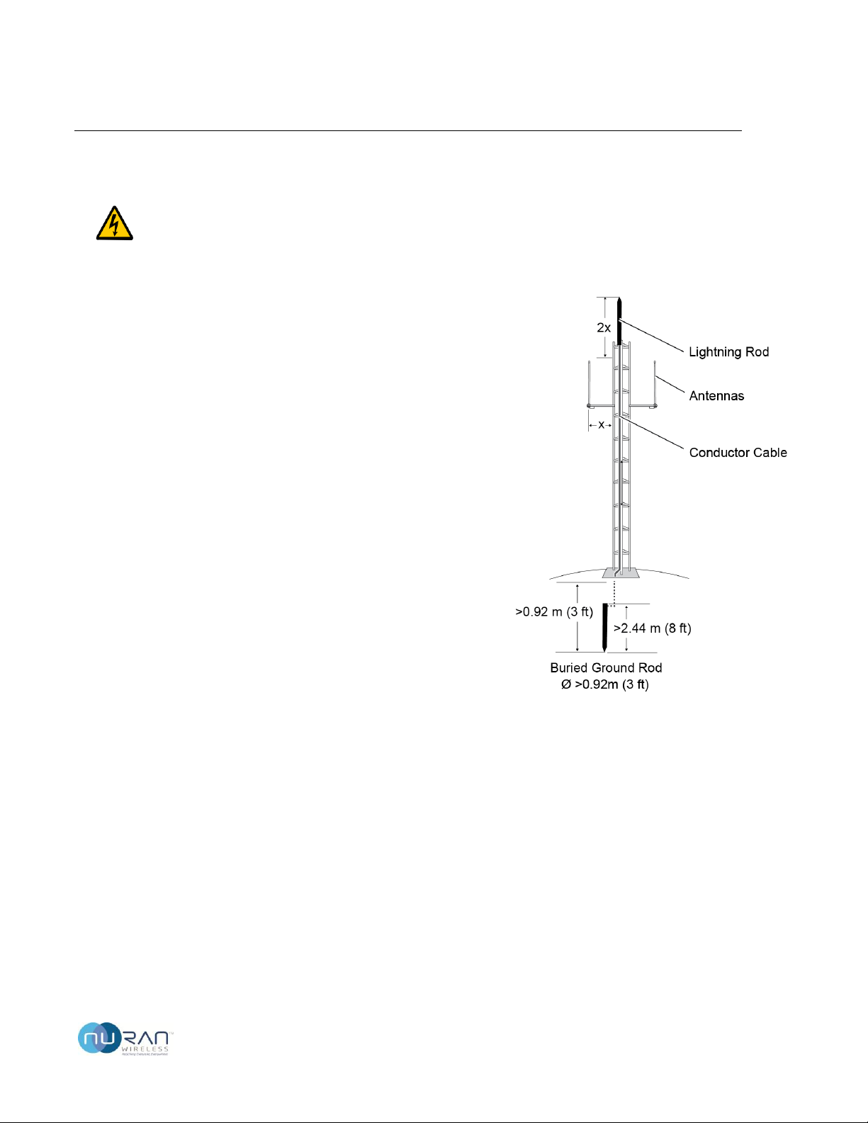
1.6 Tower Lightning Protection .............................................................................................. 9
1.7 Waterproofing Connectors ............................................................................................. 10
1.8 Drip Loops ....................................................................................................................... 10
1.9 Litecell Contents.............................................................................................................. 11
1.10 Deployment Kit Contents............................................................................................ 11
1.11 Product Warranty........................................................................................................ 12
1.12 Acronyms and Abbreviations ...................................................................................... 12
2Hardware Description....................................................................................................13
2.1 GSM LiteCell .................................................................................................................... 15
2.1.1 Mechanical Specifications ..................................................................................... 15
2.1.2 Electrical Specifications ......................................................................................... 17
2.1.3 Environmental Specifications ................................................................................ 17
2.1.4 RF Specifications.................................................................................................... 17
2.1.5 Mounting Hardware Specifications ....................................................................... 18
2.2 Network Specifications ................................................................................................... 18
2.3 GSM Antennas ................................................................................................................ 20
2.3.1 Antenna Separation............................................................................................... 20
2.3.2 Models ................................................................................................................... 20
2.3.3 RF Cable ................................................................................................................. 21
2.3.4 Mounting Hardware .............................................................................................. 21
2.4 GPS Antenna ................................................................................................................... 22
2.4.1 Model..................................................................................................................... 23
2.5 Power .............................................................................................................................. 23
2.5.1 Deployment Kit AC Power Supply ......................................................................... 24
2.5.2 Deployment Kit DC Power Cord ............................................................................ 25
3Installation Procedures..................................................................................................27
3.1 Provision GSM LiteCell .................................................................................................... 27

GSM LiteCell Installation Guide Version 0.95
CONFIDENTIAL 5 of 40
3.2 Prepare for Installation................................................................................................... 27
3.2.1 Required Tools....................................................................................................... 27
3.2.2 Safety Equipment .................................................................................................. 28
3.2.3 Cable Guidelines.................................................................................................... 28
3.3 Install GSM Antennas...................................................................................................... 28
3.4 Install GPS Antenna ........................................................................................................ 31
3.5 Install GSM LiteCell ......................................................................................................... 32
3.6 Install Power Supply ....................................................................................................... 34
3.7 Grounding and Lightning Protection Guidelines ............................................................ 35
3.8 LED Activity and System Operation ................................................................................ 37
3.8.1 LiteCell LED Colors and Flashing Patterns ............................................................. 37
3.8.2 LED Indication Priority........................................................................................... 39

GSM LiteCell Installation Guide Version 0.95
CONFIDENTIAL 6 of 40
Figures and Tables
Figures
Figure 1. Tower Lightning Protection.......................................................................................... 9
Figure 2. Waterproofing Connectors ........................................................................................ 10
Figure 3. Drip Loop .................................................................................................................... 10
Figure 4. Base Station Installed Using Deployment Kit (AC Powered)...................................... 13
Figure 5. Base Station Powered By Solar Panels....................................................................... 14
Figure 6. GSM LiteCell ............................................................................................................... 15
Figure 7. Deployment Kit GPS Antenna..................................................................................... 22
Figure 8. Deployment Kit Power Supply.................................................................................... 24
Figure 9. GSM Antenna Installation .......................................................................................... 29
Figure 10. GPS Antenna Installation............................................................................................ 31
Figure 11. GSM LiteCell Installation ............................................................................................ 32
Figure 12. Power Supply Installation........................................................................................... 34
Figure 13. Grounding and Lightning Protection.......................................................................... 36
Figure 14. GSM LiteCell LED ........................................................................................................ 37
Tables
Table 1 GSM LiteCell Mechanical Specifications .................................................................... 15
Table 2 GSM LiteCell Electrical Specifications ........................................................................ 17
Table 3 GSM LiteCell Environmental Specifications ............................................................... 17
Table 4 GSM LiteCell RF Specifications ................................................................................... 17
Table 5 GSM LiteCell Mounting Hardware ............................................................................. 18
Table 6 General GSM Antenna Specifications ........................................................................ 20
Table 7 Deployment Kit GSM Antennas.................................................................................. 20
Table 8 GSM Antenna Deployment Kit Hardware .................................................................. 21
Table 9 General GPS Antenna Specifications 1....................................................................... 22
Table 10 Deployment Kit GPS Antenna..................................................................................... 23
Table 11 Deployment Kit Power Supply Specifications ............................................................ 23
Table 12 Deployment Kit Power Supply Specifications ............................................................ 24

GSM LiteCell Installation Guide Version 0.95
CONFIDENTIAL 7 of 40
1 Introduction
This document explains how to install the GSM LiteCell, an easy-to-deploy and low-power
consumption cellular base station.
1.1 Scope
This document covers installation requirements, site preparation, and physical equipment
installation. After completing these procedures, the base station equipment will be powered on
and ready for configuration.
1.2 Intended Audience
This document is intended for installation technicians. The reader should have a basic
understanding of electricity, telecommunications equipment, and RF technology.
1.3 Related Documents
The following documents are included in the GSM LiteCell documentation suite:
Nuran –Return of Merchandise Policy
Nuran –Limited Product Warranty_EN_FR-4-15
GSM LiteCell Deployment Kit

GSM LiteCell Installation Guide Version 0.95
CONFIDENTIAL 8 of 40
1.4 Notices and Safety Warnings
Critical reader information is indicated throughout this document using specially formatted text
and/or icons.
NOTE: Notes contain information that may be of particular usefulness or direct the
reader's attention to issues that may cause difficulties if ignored.
CAUTION: A general caution is shown when there is risk of personal injury or
equipment damage from non-electrical hazards.
WARNING: An electrical warning is shown when there is risk of personal injury or
equipment damage from electrical hazards.
1.5 Safety Precautions
Always observe the following recommendations to ensure maximum safety:
The equipment is intended for installation in a restricted access location.
Do not install or operate the equipment without proper training.
Do not operate the equipment without the specified antennas correctly installed.
Observe all local or national RF regulations with respect to operating RF equipment.
Do not stand in front of, or in close proximity to, the antennas when they are powered on.
Do not modify the equipment, integrate with non-approved devices, or operate in a non-
approved manner.
Always follow applicable electrical codes when installing the equipment.
Disconnect power from the equipment when it is not in use for an extended period of time.
CAUTION: Remove all protective foils and packaging material prior to usage.

GSM LiteCell Installation Guide Version 0.95
CONFIDENTIAL 9 of 40
1.6 Tower Lightning Protection
WARNING: Outdoor towers are susceptible to damage caused by direct or nearby
lightning strikes. To reduce the risk of serious injury and equipment damage
caused by lightning strikes, the tower should be equipped with a lightning
protection system that is designed and installed by a qualified professional
installer and meets all applicable electrical codes.
A lightning rod should be installed on the tower above the
GSM antennas. The height must be at least twice the
distance that the antennas are mounted away from the
tower. In areas with a high frequency of lightning strikes, the
height should be increased up to 5 times this distance.
The lightning rod must be attached to a conductor cable or
grounding bus, which in turn is connected to a ground rod at
least 2.44 m (8 ft) long, 16 mm (6/8 in) in diameter, and
extends into the ground at least 0.92 m (3 ft) below any
adjacent structure.
Figure 1. Tower Lightning Protection

GSM LiteCell Installation Guide Version 0.95
CONFIDENTIAL 10 of 40
1.7 Waterproofing Connectors
All outdoor coaxial and power connectors must be waterproofed using waterproof and UV-
resistant tape.
Figure 2. Waterproofing Connectors
To cover a connector:
1. Cut a suitable length of the waterproof tape from the roll.
2. Remove the backing.
3. Starting from 2.5 cm (1 in) before the connector, wrap the entire length while stretching
the tape material. When stretched, the tape will stick to itself and form a waterproof
seal around the connector.
4. Keep wrapping until you are 2–3 cm (0.75–1.25 in) past the connector.
5. Cover the waterproof tape with a piece of UV protection tape.
1.8 Drip Loops
Whenever a cable is connected to a device, is secured to the side of a
structure, or enters a building or enclosure, form a loop with the cable so
that water follows the cable and drips away from the device, structure, or
building.
Figure 3. Drip Loop

GSM LiteCell Installation Guide Version 0.95
CONFIDENTIAL 11 of 40
1.9 Litecell Contents
The GSM LiteCell box includes the following items:
GSM Litecell
Flange nuts and screws
U-bolts and clamps
Waterproof RF cap
Power cable plug
Ethernet cable plug
1.10 Deployment Kit Contents
The GSM LiteCell deployment kit, if ordered, includes the following items:
GPS antenna with cable and SMA connector.
GPS antenna mounting hardware
2 GSM omni-direction antennas
RF cable with N-Type connectors, 4.75 m (15 ft)
15 mounting clamps (used for both GSM LiteCell and standoff pipes)
2 standoff pipes
Flange nuts and screws
Power supply fixation clamps
Waterproofing tape
UV protection tape
UV-rated tie wraps (x50)
Outdoor Ethernet cable, 50 m (164 ft) and RJ-45 connectors
Optional AC power supply or DC power cord, 50 m (164 ft)
Tool kit (screw drivers, adjustable wrench)

GSM LiteCell Installation Guide Version 0.95
CONFIDENTIAL 12 of 40
1.11 Product Warranty
For warranty information about this product, refer to your NuRan Limited Product Warranty
and any applicable service agreements.
CAUTION: The GSM LiteCell contains no user-serviceable parts. Do not open or
modify any part of the product, as this action will automatically void the product’s
warranty. All repairs must be performed by qualified service personnel. Do not use
the GSM LiteCell with any non-approved third-party products.
For customer support, contact NuRan:
Website: http://nuranwireless.com
Email: [email protected]
Telephone: (418) 914-7484
Address: 2150 Cyrille-Duqet, Quebec, QC, Canada G1N 2G3
When contacting NuRan, obtain the serial number and MAC address of your GSM LiteCell. This
information is printed on the product label and will assist in troubleshooting and resolving your
issues.
1.12 Acronyms and Abbreviations
AC
Alternating Current
Mbps
Megabits per second
ARFCN
Absolute Radio-Frequency
Channel Number
PPM
Parts Per Million
BER
Bit error rate
PSU
Power Supply Unit
DC
Direct current
RAN
Radio Access Network
EDGE
Enhanced Data rates for GSM
Evolution
RF
Radio Frequency
GSM
Global System for Mobile
Communications (GSM)
SMA
Sub Miniature version A
GPP
3rd Generation Partnership
Project
IP
Internet Protocol
GPS
Global Positioning System
IP##
Ingress Protection
LED
Light-Emitting Diode
UV
Ultraviolet light

GSM LiteCell Installation Guide Version 0.95
CONFIDENTIAL 13 of 40
2 Hardware Description
Figure 4 shows a standard GSM LiteCell base station installation that uses NuRan's optional
deployment kit. Installers may also use their own equipment, as long as it meets the
requirements specified in this document.
Figure 4. Base Station Installed Using Deployment Kit (AC Powered)

GSM LiteCell Installation Guide Version 0.95
CONFIDENTIAL 14 of 40
Figure 5. Base Station Powered By Solar Panels

GSM LiteCell Installation Guide Version 0.95
CONFIDENTIAL 15 of 40
2.1 GSM LiteCell
The GSM LiteCell is a compact GSM base station designed to be tower-mounted and positioned
near the antennas. Being a self-contained module, it has no internal components that require
technician attention during installation.
Figure 6. GSM LiteCell
2.1.1 Mechanical Specifications
The GSM LiteCell has the following mechanical specifications:
Dimensions
230 ×350 x 130 mm
Weight
9.5 kg
Mounting options
Pole, wall, or tower-mounted (mounting hardware included)
Connectors
GSM antenna: N-Type, female (2)
GPS antenna: SMA, female
Network (traffic and control): RJ-45 bayonet/screw connectors (2)
Power: 5-pin connector (power + optional serial interface)
Table 1 GSM LiteCell Mechanical Specifications

GSM LiteCell Installation Guide Version 0.95
CONFIDENTIAL 16 of 40

GSM LiteCell Installation Guide Version 0.95
CONFIDENTIAL 17 of 40
2.1.2 Electrical Specifications
The GSM LiteCell has the following electrical specifications:
Power consumption
90W (maximum, with 2 antennas @ 2x10W output)
Input voltage
24 VDC nominal (19–30 VDC)
Table 2 GSM LiteCell Electrical Specifications
2.1.3 Environmental Specifications
The GSM LiteCell has the following environmental specifications:
Operating temperature
–20 to 55 °C
Storage temperature
–40 to 70 °C
Ingress rating
IP66
Cooling
Passive
Table 3 GSM LiteCell Environmental Specifications
2.1.4 RF Specifications
The RF specifications of the GSM LiteCell are as follows:
Frequency bands
850 band: 824–850 MHz (Rx), 869–895 MHz (Tx), ARFCN 128–251
900 band: 880–915 MHz (Rx), 925–960 Mhz (Tx), ARFCN 975–1023 and 0–124
1800 band: 1710–1785 MHz (Rx), 1805–1880 (Tx), ARFCN 512–885
1900 band: 1850–1910 MHz (Rx), 1930–1990 (Tx), ARFCN 512–810
Maximum output power
10W per channel
Output power steps
1 dB
Clock accuracy
Better than 0.05 ppm
Sensitivity
–114 dBm, 2% BER
Table 4 GSM LiteCell RF Specifications

GSM LiteCell Installation Guide Version 0.95
CONFIDENTIAL 18 of 40
2.1.5 Mounting Hardware Specifications
The GSM LiteCell includes the following mounting hardware:
Hardware
Image
Description
Mounting brackets
The GSM LiteCell attaches to the tower structure
using a pair of custom brackets and two M8 U-
bolts and screws.
The brackets are designed for right-angled
mounting and support poles with a diameter of
32 to 60 mm (1.25–2.25 in).
Table 5 GSM LiteCell Mounting Hardware
2.2 Network Specifications
The GSM LiteCell includes two RJ-45 ports with waterproof metallic IP67 bayonet/screw
connectors. One port is used for the Abis interface while the other can be used to daisy-chain
multiple base stations together. One RJ-45 connector metallic cap is provided as well ahd shall
be installed on any unused port to ensure IP66 is respected.
When connecting the GSM LiteCell, use outdoor-rated CAT5e Ethernet cable. The optional
deployment kit includes a 50 m (165 ft) Ethernet cable with a GSM LiteCell compatible
connector on one end ad a standard RJ-45 connector on the other.
The following steps may be used to install the provided Ethernet connector on an RJ45 cable.
1. Insert the nut, white pad and grommet on the cable.

GSM LiteCell Installation Guide Version 0.95
CONFIDENTIAL 19 of 40
2. An off-the-shelf modular cable cannot be used, the body is too long. Build a cable using
shielded plug similar to the one showed below. It is important to cut the clip of the
connector to avoid problems once the cable is connected to the Litecell.
3. insert the plug in the shell.
4. Remove the connector from the Litecell. The plug is at the right distance.

GSM LiteCell Installation Guide Version 0.95
CONFIDENTIAL 20 of 40
2.3 GSM Antennas
The GSM LiteCell requires two antennas, one for each TRX (RX and TX are duplexed internally).
The GSM antennas must meet the following specifications:
Impedance
50 Ohms
VSWR
<2
Power handling
20 Watts
Table 6 General GSM Antenna Specifications
2.3.1 Antenna Separation
Antennas will usually perform optimally when installed as high above the ground and tree line
as possible, be clear of any obstruction, and as far away from the tower/mast as possible.
Important:
To meet RF exposure requirements, maintain a minimum separation of 1 meter between the
antenna and the nearby persons.
2.3.2 Models
The GSM antenna model used with the base station depends on the required frequency band.
The following professional-grade omni-directional antennas are available from NuRan and are
included as part of the deployment kit. The antennas are rugged and weather-proof :
GSM300-ANT-OK-U1
GSM300-ANT-OK-E1
GSM300-ANT-OK-E2
Band (MHz)
850
900
1800
Frequency range (MHz)
806–896
870–960
1710–1880, 2100–2155
Gain
8 dBi
8 dBi
9 dBi
Polarization
Vertical
Vertical
Vertical
Horizontal beamwidth
360°
360°
360°
Vertical beamwidth
25°
25°
20°
VSWR
<1.5
<1.5
<2
Impedance
50 Ohms
50 Ohms
50 Ohms
Connector
N-type, female
N-type, female
N-type, female
Wind load
17lbs@100mph
17lbs@100mph
11lbs@100mph
Dimensions
25x1650 mm
25x1450 mm
25x1250 mm
Weight
2.5 kg
2.5 kg
1.3 kg
Table 7 Deployment Kit GSM Antennas
Table of contents
Popular Accessories manuals by other brands

SICK
SICK GLD20 operating instructions

Dorner
Dorner AquaPruf 7400 Ultimate CE Series Installation, Maintenance, and Parts Manual

Masimo
Masimo rainbow ReSposable Pulse CO-Oximeter Training manual

Hytronik
Hytronik HC401SRC/R instruction manual

KingsBottle
KingsBottle KBU-56 SERIES user manual

Emos
Emos AlphaQ 10 user manual