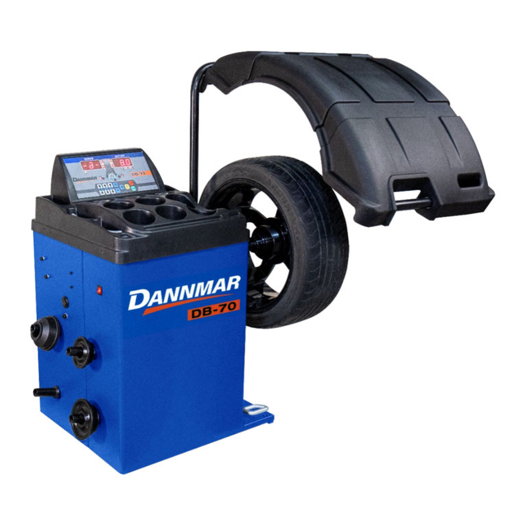
Dannmar B-200 Instruction Manual

Dannmar
R
EQUIPMENT


Page1
INDEX
1.
Preface
Pag. 2
2.
Safety regulations
Pag. 3
3.
Carriage, hoisting, storage and transportation of the machine
Pag. 3
4.
Installation and switching on
Pag. 5
5.
Installation
Pag. 6
6.
Suspension of the use
Pag. 6
7.
Environmental information
Pag. 6
8.
Technical data
Pag. 7
9.
Routine maintenance of the wheel balancer
Pag. 8
10.
Monitor
Pag. 9
11.
Keyboard
Pag. 10
12.
Operating modes standard, service, stand by
Pag. 10
13.
Machine calibration
Pag. 11
14.
Use of the machine in NORMAL MODE
Pag. 16
15.
Optimization
Pag. 26
16.
Hidden weights program
Pag. 28
17.
Second operator
Pag. 30
18.
Utility programs
Pag. 31
19.
Error codes
Pag. 39
20.
Fire prevention means to use
Pag. 40
Page.41

Page2
1. PREFACE
Confirming the machine including the operation system, tools and accessories are operated normally and without any damage, you
hand the machine to the customers and the machine will endue some period of guarantee. During this period, the manufacturer
will repair the machine or the no-normal parts of the machine or machine itself free of charge but will not be responsible for the
damage and wear and tear caused by the no-normal usage, transportation and maintenance. And the manufacturer will not notify
the customers when he renews the products or improves the production line. The purpose of this manual is to provide the users
and owners of this machine with the guide of safety and regulation to make the operators properly maintenance and operates the
machine. If you carefully follow this instruction manual, the machine will provide you with the service of higher efficiency and more
durable. The following paragraphs will provide you with the danger level related to the machine.
Danger: operation can cause the serious injury or death.
Warning: operation can cause the serious damage or unsafe.
Caution: operation can cause slight wound and the damage of
the objects.
*Read the manual carefully before use the machine and keep this manual on the document folder near the machine for check at
any time.
* Technical document should be considered to be the integrated part of the machine and it should be placed together with the
machine when being sold to the new owner.
*Only when the series number and model of the manual are same to the series number and model on the nameplate, the manual
can be considered to be effective.
* Firmly keep in mind and follow the description and information of this manual at any time and the operators should be
responsible for the operations not described and authorized in the manual.
* Some information of the manual comes from the pictures, it is normal that you will see some differences to the standard
machines.
* Do not try the other operations except under the guidance of the personnel with experience. If necessary, please contact with the
authorized service center for help.
The select of the installation site must be in accordance with the current effective safety regulation. We should specially point out
that the installation and operation of the machine must have the anti-moisture protective methods. If you want to correctly and
safely use the machine, you should meet the following environment requirements:
- Luminosity in site should be at least 300 lux.

Page3
-RD:<85% (without condensation).
- Environment temperature: 0°-50°C.
- The floor of the ground should be enough solid to support the maximum weight of the machine.
- The machine should not be used in the environment with the potential exploded factors.
2. SAFETY REGULATIONS
* Not following the information and overlooking the warning labels will cause the series injuries to the operators and the other
personnel.
* You can operate the machines after you completely read and understand the entire damages/warnings.
* The correct use of the machine needs the professional operator who must undertake the suitable training and can understand
the written descriptions of the manufacturer, familiar with the safety regulations and follow all these descriptions and regulations.
And mean while the operator should be a person without bad habit and of healthy of mentality and physiology.
Before operating the machine, you must have the following conditions:
- Read and understand the information and the description in the manual
- Fully understand the characteristic and the features of the machine
- Keep the unauthorized personnel from the operative site
- Be sure the installation should be in accordance with the current standard and the regulation
- Be sure that the operators of the machine should enduce the proper training and operate the machine correctly and safety.
- Before power off the machine, do not touch the cables, motors or other electrical elements.
Do not remove or wear out any label of danger, caution and warning or instruction. If the label is lost or fuzzy, you should change it
at once. If the label is missing, please contact with the nearest dealer to get it.
- See the accident precaution regulation related to the operation and maintenance of the mechanism of high voltage and rotation
- The manufacturer will not be responsible for the damage and accident caused by the changes and modifications not authorized by
the manufacturer.
3. CARRIAGE, HOISTING, STORAGE AND TRANSPORTATION OF THE MACHINE
Place, transport and store the machine according to the indication on the package container. When transport and hoist the wheel
balancer, do not make the accessory hang, weight tray, balance shaft and display cover to be the weight bearing area because this
can cause the damage of the machine or the precision error and even the injury to the operator. According to the construction of
the wheel balancer, the center of gravity is on the right off-center, therefore when lift the machine unpacked, the lift arm of the
hydraulic vertical lift of the forklift should be deflect to the right meaning not exceed 1/4 of the width of the machine. It is best to
cover a layer of paper shell and rubber to avoid the slide of the machine. When lift and slide the machine, there should be the
personnel to hold the machine and the maximum height of lifting should not exceed one meter. If exceeding one meter, you should
fix the machine properly.
If hoist the wheel balancer, you can pass the wide cloth band through the clearance under the machine. The cloth band must be 2
pieces or more than 2pieces and the load bearing should be more than 500kg and the length should be of same. The position of the
cloth band should be in accordance with the requirement of lifting the machine. When hoist, it is best that some personnel to hold
the machine. When lift or hoist the machine, the speed should be not more than 35mm/s for fear that the much inertia causing the
slide and swing of the machine to cause the dangerous.
Page4
Storage: The machine should not be exposed and should be covered with the plastic film. The machine should be stored in the
warehouse of ventilation, dry and waterproof. In the storage area, the temperature should be controlled in the range of -10℃~55℃
and RH should be controlled in the range of 30%~90%. It is forbidden to store the machine together with the dangerous chemical,
the inflammable and explosive materials or the objects easy to born the dust.
Transportation:The load of the machine should be accordance with the indication on the outer package and fix firmly. No matter
what kind of transportation, the environment temperature and humidity should comply with the requirement of the storage
requirement specified in term2.2. It is forbidden transport the machine together with the dangerous chemicals, inflammable and
explosive materials or the objects easy to born the dust.
Installation
After confirming the package of the wheel balancer intact, you can carry the machine to the installation area as shown in the Fig1
Environment requirement at the installation site: Temperature 0℃-50℃,RH≤85%, without water source, fire source, dust,
inflammable and explosive materials and the chemicals. The floor should be flat and solid.
Before installation, detach the upper cover of the package box of the wheel balancer and confirm the machines, accessories
shipped together with the machine and the data you purchase according to the packing list. If you have any question, you can
contact with the dealers. The packing material such as plastic, polystyrene, nail, screw, wood and the carton must be placed into a
scrap box and handle according to the local law and regulation. When install, detach the connect bolt between the wheel balancer
and the pallet of the package box and move the machine from the pallet to the installation position. To guarantee the safety and
fast of the operation, there should be the distance more than 300cm from the wall of the building to the right and rear of the
machine. And the distance of more than 200cm from the wall of the building to the left of the machine. After the wheel balancer is
moved to the proper position, drill 3 anchor holes on the ground according to the installation hole at the foot of the machine and
then use 3 pieces of M10X160 anchor screws to fix the machine on the ground to guarantee the stability and reliability of the
machine.
If the machine is not packed, observe following precautions:
PROTECT THE SHARP EDGES AT THE ENDS WITH SUITABLE MATERIAL (Bubble wrap or cardboard).
DO NOT USE METAL WIRE ROPES FOR LIFTING BOARD.
SLING WITH STRAPS OF AT LEAST 200 cm IN LENGHT AND WITH A HIGHER FLOW RATE OF 500 kg.
DO NOT FORCE ON SHAFT AND/OR FLANGE.
ALWAYS UNPLUG THE POWER SUPPLY CABLE FROM THE SOCKET BEFORE MOVING THE MACHINE.

Page5
4. INSTALLATION AND SWITCHING ON
After unpacking wheel balancer, check the status of integrity and presence of faults, make the assembly of the component as
shown in following pictures.
4.1 Electrical connection
The standard version of the machine must be connected to a mains 110V Single Phase.
The change of the power supply cannot be realized by the user; it must be requested to BRIGHT or to a dealer or to an authorized
service center. To accomplish the electric connection, connect the machine’s power supply cable with the plug in use in the country.
ALL OPERATIONS TO MAKE ELECTRICAL CONNECTION AND INTERVENTIONS (HOWEVER LIGHT) ON
ELECTRICAL PARTS MUST BE CARRIED OUT BY QUALIFIED PERSONNEL.
The dimensioning of electrical connection must be carried out in according to electric power absorbed by the machine. The
absorption is specified in paragraph 10. The user must:
- Check that the supply voltage correspond to the voltage indicate on the nameplate of the machine;
- Check the conditions of the wire and the presence of the ground conductor;
- Check the machine is connected to its own electrical connection, fitted with a proper 30 mA sensitive automatic circuit breaker,
against a possible electrical overload over 30 mA;
- Connect the power supply cable to the plug with great care and following to the current regulations.
WHEN THE MACHINE IS TURNED OFF FOR A LONG TIME IT IS NECESSARY TO DISCONNECT THE POWER
PLUG TO AVOID USE BY UNAUTHORIZED PERSONNEL.
IF THE MACHINE IS CONNECTED DIRECTLY TO THE POWER SUPPLY BY MEANS OF THE MAIN ELECTRICAL
BOARD AND WITHOUT THE USE OF A PLUG, INSTALL A KEY-OPERATED SWITCH TO RESCTRICT THE
MACHINE USE EXCLUSIVELY TO QUALIFIED PERSONNEL.
IN CASE OF OPERATIONS ON ELECTRIC PARTS, CABLES ENGINES OR ANY ELECTRIC DEVICES, IT IS NECESSARY
TO CUT OFF THE ELECTRICITY.
DO NOT REMOVE, DAMAGE AND MAKE COMPLETELY ILLEGIBLE THE STICKERS OF DANGER, WARNING,
INSTRUCTIONS AND CAUTION. REPLACE ANY MISSING, DAMAGED OR ILLEGIBLE STICKERS. THE STICKERS
CAN BE FOUND AT THE NEAREST DEALER OF MANUFACTURER.
THE DAMAGE FOR FAILURE TO COMPLY WITH THE ABOVE WRITTEN INSTRUCTIONS, IT WOULD BE NOT
CHARGED AGAINST THE MANUFACTURER AND IT MAY CAUSE THE INVALIDATION OF THE WARRANTY.

Page6
5. INSTALLATION
5.1 Installation area
To install the machine you need a useful space on the basis of the information given in picture F5.1.
Picture F5.1
From working position, the user must be able to view the machine and the surrounding area.
INSTALLATION AREA MUST BE KEEP CLEAR BY POSSIBLE DANGEROUS OBJECTS.
UNAUTHORIZED PERSONNEL MUST NOT STAND NEAR BY THE WORKING AND INSTALLATION AREAS.
THE MACHINE MUST BE PLACED ON A HORIZONTAL SURFACE RATHER MADE OF CONCRETE OR TILED.
AVOID BREAKABLE AND ROUGH SURFACES.
SURFACE MUST ENDURE THE STRESS LOAD DURING THE MACHINE OPERATION.
THE MACHINE MUST BE FIXED ON THE FLOOR WITH SCREWS AND EXPANSION PLUGS IN ACCORDING TO
FOLLOWING INSTRUCTIONS.
THE USE OF THE MACHINE IS ONLY ALLOWED IN PLACES THAT DO NOT PRESENT RISKS OF EXPLOSION OR
FIRE.
6. SUSPENSION OF THE USE
In case the machine is not used for a long time it is necessary to disconnect the power supply and protect all parts that could be
damaged by dust. Grease all parts that could be damaged in case of oxidation. In this specific case, protect the shaft and flange.
7. ENVIRONMENTAL INFORMATION
THE DISPOSAL PROCEDURE DESCRIBED BELOW ONLY APPLIES TO MACHINES
WITH THE SYMBOL OF THE WASTE BIN WITH A BAR ACROSS IT ON THEIR DATA
PLATES.
The crossed-out bin symbol, placed on the product and on this page, reminds the user that the product must be disposed of
properly at the end of its life. This product may contain substances that can be hazardous to the environment and to human health
if it is not disposed of properly. We are therefore providing you with the information below in order to prevent these substances
from being released into the environment and to improve the use of natural resources.

Page7
Electrical and electronic equipment must never be disposed of in the usual municipal waste but must be separately collected for
their proper treatment.
Thus, the hazardous consequences that non-specific treatments of the substances contained in these products, or improper use of
parts of them, may have on the environment or on human health are prevented. Furthermore, this helps to recover, recycle and
reuse many of the materials contained in these products. Electrical and electronic manufacturers and distributors set up proper
collection and treatment systems for these products for this purpose. At the end of the product’s working life contact your supplier
for information about disposal procedures. When you purchase this product, your supplier will also inform you that you may return
another worn-out appliance to him free of charge, provided it is of the same type and has provided the same functions as the
product just purchased.
Any disposal of the product performed in a different way from that described above will be liable to the penalties provided for by
the nation regulations in force in the country where the product is disposed of.
Further measures for environmental protection are recommended: recycling of any packaging of the product and proper disposal
for used batteries (only if contained in the product).
8. TECHNICAL DATA
General features
Power supply voltage(1)
110V
Power consumption
90 W
Balancing speed
140 rpm
Maximum unbalance calculated
200 gr.
Accuracy
± 1 gr.
Shaft diameter
40 mm
Working environment temperature
0°-- + 50°C
Storage temperature
-10°-- + 50°C
Storage relative humidity
30% -- 80%
Machine weight (without accessories)
328.5 lbs.
Noise level
<70 dB(A)

Page8
9. ROUTINE MAINTENANCE OF THE WHEEL BALANCER
Warning
The manufacturer declines all responsibility in the event of claims resulting from the use of non-original spare parts or accessories.
Warning
Unplug the machine from the socket and make sure that all moving parts have been locked before performing any adjustment or
maintenance operation.
Warning
Do not remove or modify any part of the machine (except for service interventions).
Caution
Keep the work area clean.
Never use compressed air and/or jets of water to remove dirt or residues from the machine. Take all possible measures to prevent
dust from building up or rising during cleaning operations. Keep the wheel balancer shaft, the securing ring nut, the centering cones
and flange clean. These components can be cleaned using a brush previously dripped in environmentally friendly solvents. Handle
cones and flanges carefully so as to avoid accidental dropping and subsequent damage that would affect centring accuracy. After
use, store cones and flanges in a place where they are suitably protected from dust and dirt. If necessary, use ethyl alcohol to clean
the display panel. Perform the calibration procedure at least once every six months.

Page9
10.MONITOR
The machine's control monitor is illustrated in figure F10.1. The control monitor is used by the operator to view the applied
controls and the data entered with the keyboard. The same control panel displays the balancing results and machine messages. The
control key functions are described in table T10.1.
Picture F10.1: Monitor
Table T10.1: Functions of different parts of the control monitor
Pos.
Description
1
Status icon band.
2 –3
Display shows unbalance value inside –outside.
4
Imbalance Position indicator. Position depends by the Program and Wheel Type selected.
5
Control icon band.
6 –7
Indicator shows angular unbalance position inner - outer.
8
Wheel dimensions data band.
4
3
7
2
1
5
8
6

Page10
11.KEYBOARD
In this manual, the keys are numbered for convenience from [1] to [9] as shown in picture F11.1. The nine keys have only one
primary function.
Picture F11.1: Keyboard
Table T11.1: Functions of the keys
Pos.
Description
1 –2 –3 - 4
Function selection keys.
5
“Back” key to go back to the previous view.
6
“Enter” key to confirm selection.
7
Quick menu( control illuminator)
8
“Start” key to start the motor.
9
“Stop” key to stop the motor.
STAND BY led
Machine status led.
12. OPERATING MODES STANDARD, SERVICE, STAND-BY
The machine features three operating modes:
STANDARD mode. This mode is enabled after the machine is turned on and it is possible to perform the wheels balancing;
SERVICE mode. In this mode various utility programs are available for setting parameters (such as grams or ounces) or
checking the machine operations (such calibration);
STAND-BY mode. After 5 minutes without user activity, the machine automatically switch to STAND-BY mode to reduce
electrical consumption (both with wheel guard raised or lowered). The STAND-BY green led on the control panel is
blinking it means the machine is in this operating mode. All acquired data and settings are held in STAND-BY mode. In the
SERVICE mode is not possible to switch to STAND-BY mode.
To exit from STAND-BY mode choose by any of the following means:
Press any keys;
Turn manually the wheel;
Pull out the distance/diameter sensor from idle position (only for the models with automatic acquisition of
distance/diameter);
Pull out the external sensor from idle position (only for the models with automatic acquisition of width.
Note: the machine exits the STAND-BY mode also by pressing the key [8] Start or lowering the wheel guard. In these cases
simultaneously will be start also the spinning (if you press [8] Start the spin will start only if the wheel guard is already lowered).
2
3
1
4
7
5
6
8
9

Page11
13.MACHINE CALIBRATION
To function properly, the machine must be calibrated. Calibration allows storing the mechanical and electrical parameters specific
to each machine so provide the best balancing results.
13.1 Machine calibration for the CAR/SUV Wheel Type
The calibration for the CAR wheel type and SUV wheel type is the same.
To perform machine calibration, you must first provide for the following material:
A balanced wheel with steel rim that has the following dimensions: diameter from 14” ------16”.
It is not possible to use wheels with aluminum rims.
A 50 grams weight (preferably in Iron or Zinc).
To perform the calibration machine, proceed as follows:
Op.
Description
10
Press [2] or [4] from the keyboard and select the
icon relative to the programme to be used.
20
Activate the AUTO/SUV calibration programme by selecting which will
turn green.
30
Confirm activation of the AUTO/SUV calibration programme by pressing [6] on
the keyboard.
40
Remove the wheel and any other accessories from the shaft.
50
Lower the wheel guard: the machine will run a launch.
60
Fit the wheel on the shaft.
Manually enter the wheel dimensions.
If the dimensions of the wheel were introduced before entering the calibration
program, this step can be skipped. It is not possible to enter the data with the
automatic acquisition system.

Page12
70
Extract the distance sensor and place it on the wheel as shown here.
Read the distance value on the graduated scale. The distance value is always
expressed in millimetres.
80
Select which type of dimension to enter by pressing [2] or [4] on the keyboard
and activate the wheel - machine distance
insertion function by selecting which will turn green.
90
Enter the reading by pressing [1] or [3] on the keyboard
.
100
Measure the width of the wheel with the special gauge or read the value of the
width indicated on the rim. The value of the width can be in inches or
millimetres according to the selected unit of measure.
110
Select which type of dimension to enter by pressing [2] or [4] on the keyboard
and activate the wheel width insertion function
by selecting which will turn green.
120
Enter the reading by pressing [1] or [3] on the keyboard
.
130
Select which type of dimension to enter by pressing [2] or [4] on the keyboard
and activate the wheel diameter insertion
function by selecting which will turn green.
140
Read the value of the diameter indicated on the rim or tire. The value of the
diameter can be in inches or millimetres according to the selected unit of
measure.

Page13
150
Enter the reading by pressing [1] or [3] on the keyboard
.
160
Lower the wheel guard: the machine will run a launch.
170
By hand, turn the wheel in the direction marked by the arrow until you see
50 g on the left display.
180
On the inner side of the wheel, at 12 o'clock, apply the 50 g weight.
190
Lower the wheel guard: the machine will run a launch.
200
Remove the 50 gr. weight applied on the internal side.
By hand, turn the wheel in the direction marked by the arrow until you see
50 g on the right display.
210
On the outer side of the wheel, at 12 o'clock, apply the 50 g weight.
220
Lower the wheel guard: the machine will run a launch.
230
If the balancing machine is equipped with the electromagnetic brake
for positioning, at the end of the previous spin the machine will
perform a set of short spins to calibrate the function of automatic sop
on imbalance position (see chapter SWI Stop the wheel on imbalance). Do
not lift the wheel guard and do not press [9] key during this procedure.

Page14
240
Calibration is finished: the machine automatically exits the calibration program
and returns to the NORMAL mode, ready to perform the balancing.
At any time it is possible to exit the calibration procedure by pressing [5] key.
13.2 Machine calibration for the MOTO wheel type
The calibration for MOTO wheel type (motorcycle wheels) is completely separated from CAR/SUV wheel type because in the
calibration for MOTO a specific adaptor for motorcycle wheels is used
If the calibration for MOTO wheel type has not been done and the user try to spin the wheel for balancing in the MOTO wheel type
mode, the machine will not run and will display an error code ERR 031.
To perform the machine calibration with adaptor for motorcycle wheels, proceed as follows:
Op.
Description
10
Press [2] or [4] from the keyboard and select
the icon relative to the programme to be used.
20
Activate the MOTO calibration programme by selecting which will
turn green.
30
Confirm activation of the MOTO calibration programme by pressing [6] on the
keyboard.
40
Mount the motorcycle adaptor on the shaft as shown here.
50
Lower the wheel guard: the machine will run a launch.
CA
CAL
CAL
CAL
CAL
CAL
CAL

Page15
60
At the end of the launch, the machine will display the message shown here.
Apply the calibration weight to the inner side, as shown. The calibration weight
must be applied on the hole marked with the “CAL” inscription.
70
Lower the wheel guard: the machine will run a launch.
80
Move the motorcycle adaptor to a stable vertical position with the calibration
weight at the top as shown in the figure. If the weight position is significantly
different from the vertical position, the machine will refuse to perform the spin
and it will display an error code ERR 043. If the motorcycle adaptor is near to
the vertical position but not in the precise vertical position, the machine will spin
but at the end of the calibration each balancing spin will have an error in the
balancing angular position of the weights.
90
Lower the wheel guard: the machine will run a launch.
100
At the end of the launch, the machine will display the message shown here.
Apply the calibration weight to the outer side as seen here. The calibration
weight must be applied on the hole marked with the “CAL” inscription.
110
Move the motorcycle adaptor to a stable vertical position with the calibration
weight at the top as shown in the figure. If the weight position is significantly
different from the vertical position, the machine will refuse to perform the spin
and it will display an error code ERR 043.
120
Lower the wheel guard: the machine will run a launch.
130
At the end of the spin, the MOTO wheel type calibration is finished and the
machine will switch to NORMAL mode, ready to run the balancing.
When the calibration is finished the MOTO wheel type and ALU1 Program Type value are set. Also the wheel data are automatically
set by machine for this type of calibration.
At any time it is always possible to exit the calibration procedure during its progress by pressing the [5] key. The MOTO wheel type
and the ALU1 Program Type will remain set. The wheel dimensions will be those which were automatically set by the machine for
this kind of calibration.

Page16
14.USE OF THE MACHINE IN NORMAL MODE
The machine allows the choice between eight different Program Type of balancing as listed in table T14.1.
Table T14.1: Program Types available
Program Type
Wheel
material
Weight position along the rim
selection
Automatic
acquisition(1)
Notes
STD
Steel
Default
2 sensors
Default at power on
ALU1
Aluminium
Default
2 sensors
Forcibly set when the Motorbike
Program Type is selected
ALU2
Aluminium
Default
2 sensors
ALU3
Aluminium
Default
2 sensors
ALU4
Aluminium
Default
2 sensors
ALU5
Aluminium
Default
2 sensors
ALS1
Aluminium
Default inner weight, outer
weight provided by user
1 sensor
ALS2
Aluminium
Provided by user
1 sensor
14.1 Type of program (Program Type)
To select the programs in NORMAL mode proceed as follows:
Op.
Description
10
and select the
Press [2] or [4] from the keyboard
icon relative to the program to be used.
20
(by default at start-
Activate the STANDARD program by selecting
up) which will turn green.
Scroll through the list of available programs by pressing [1] or [3] on the
keyboard.
- - - - - -
The position of the balancing weights along the section of the rim in the various Program Types is shown in picture F14.1.

Page17
Picture F14.1: Position of the weights in the various Program Types along the section of the rim
Angular position of the balancing weights in the several Program Type is shown in table T14.2.
Table T14.2: Angular position of the balancing weights in the various Program Types
Machine data
acquisition
system
Program Type
STD,
ALU1,2,3,4,5
ALS1
ALS2
Internal
plane
External
plane
Static
plane
Internal
plane
External
plane
Static
plane
Internal
plane
External
plane
Static
plane
Semi-automatic
H12
H12
H12
H12
Sensor-
rim
contact
point(1)
H6
Sensor-
rim
contact
point(1)
Sensor-
rim
contact
point(1)
H6
Automatic
H12
H12
H12
H12
Sensor-
rim
contact
point(1)
H6
Sensor-
rim
contact
point(1)
Sensor-
rim
contact
point(1)
H6
Laser
H12
H12
H12
H12
H6
Sticker
H6
H6
Sticker
H6
Sticker
H6
Note (1): if the data acquisition system is disabled, the angular position of the weight will be in the 6 o’clock position.
In table T15.2 the symbol “H12” indicates that the angular position of the weight is at 12 o’clock while the symbol “H6” indicates
that the angular position of the weight is at 6 o’clock.
The machine data acquisition systems are defined as follows:
Semi-automatic when the Distance and Diameter data are automatically acquired with the Distance/Diameter sensor
while the data on the width must be manually entered;
Automatic when all data of the rim is automatically acquired with the two sensors.

Page18
14.2 Wheel types
The machine allows choosing between three different Wheel Types as listed in table T14.3.
Table T14.3: Wheel Types to select
Wheel Type
Vehicle
Notes
CAR
Auto-vehicles
Default power on
MOTO
Motorbikes
Forcibly set the ALU1 Program Type
SUV
Off-Road vehicles
Not suitable for balancing truck wheels
To select a specific wheel type, proceed as follows:
Op.
Description
10
and select the
Press [2] or [4] from the keyboard
icon relative to the program to be used.
20
(by default at start-up)
Activate the AUTO program by selecting
which will turn green.
30
Scroll through the list of available program by pressing [1] or [3] on the
keyboard
and activate the MOTO program by
selecting .
40
Scroll through the list of available program by pressing [1] or [3] on the
keyboard
and activate the SUV program by
selecting .
Table of contents
Other Dannmar Wheel Balancer manuals
Popular Wheel Balancer manuals by other brands

Fasep
Fasep VIDEOTRONIC V653.G2 user manual

John Bean
John Bean VPI System IV Operation instructions

Hofmann
Hofmann geodyna OPTIMA II Operation manual

National Auto Tools
National Auto Tools NTB-800 manual

HENNESSY INDUSTRIES
HENNESSY INDUSTRIES Coats Vero Series manual

Hunter
Hunter Road Force Elite GSP9700 Series Operation instructions