Basic Setup:
1. Remove 1701+ Base and 1701+ Link(s) from packaging.
2. (Optional) Join the adapters together using a password. See Join instructions.
3. (Optional) Connect either NV-EC4BNC or NV-BNCA adapters to cable
infrastructure.
4. Ensure cables are properly terminated before connecting any 1701+ products.
5. Remove all legacy equipment from the cable infrastructure. NOTE: In order to
avoid damage to endpoints, it is important that non-IP devices are not connected
when you connect the 1701+ Base.
6. At the head end, connect the 1701+ Base to the switch and cable infrastructure.
a. (Optional) Connect the 1701+ Base to the power supply. This can be skipped if
the 1701+ Base is connected to a POE switch. (Note: the 1701+ Base can only
draw 30W from a PoE switch)
7. Using CAT5e or higher category cable, connect the endpoint to 1701+ Link.
a. (Optional) If required, connect a power supply to the 1701+ Link. This is
recommended if the endpoint draws greater than 25W.
8. Connect the 1701+ Link to the cable infrastructure. Verify that the Power and
Link LEDs are on.
9. Repeat steps 7-8 for each 1701+ Link being connected to the 1701+ Base.
Join / Factory Reset
By default, all 1701+ devices come pre-joined and ready to communicate with other
1701+. However, it is possible to have a group of 1701+ joined under a unique password
via two ways:
1. Visit our 1701+ Products page at www.nvtphybridge.com to download the 1701+
Configuration Tool.
2. Use the join button to join multiple adapters together.
To use the join button:
(Note: a paperclip or other thin item will be needed to press the join button.)
1. (Optional) If the adapters have already been in use, factory reset them all by
pressing their join button for at least 15 seconds. The LEDs on the unit will
perform 1 slow blink if done correctly.
2. On the 1701+ Base, press the join button for 10 seconds to generate a new
random password. If done correctly, the LEDs will blink slowly 5 times.
3. Make sure the 1701+ Base is connected to the 1701+ Link(s) for next step: (Note:
this step must be done quickly)
a. Press the join button on the 1701+ Base for 1 second. The join LED will start
blinking.
b. Press the join button on the 1701+ Link for 1 second. Both join LEDs will start
blinking rapidly.
c. Repeat step 3 for each 1701+ Link being connected to the 1701+ Base.
4. Once units have been joined locally, test for successful connectivity with desired
endpoints.
5. Connect to local cabling.
DC IN
37-55V
TO LRE
PWR LINK/JOIN
BUTTON
JOIN
TO SWITCH
10/100
LNK/ACT
1000
LNK/ACT
5
6
7 8
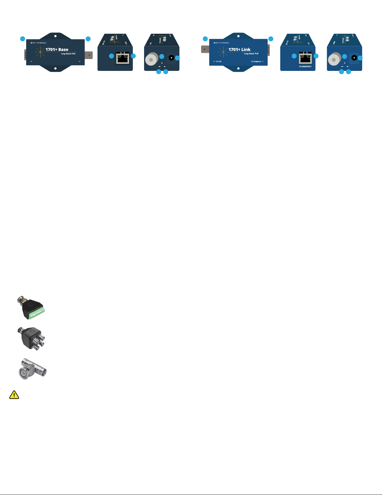
1. RJ45 Connector (To Switch)
2. BNC Connector (LRE connection)
3. Amber LED 10/100Mbit Link/Activity
4. Green LED 1000Mbit Link/Activity
5. DC input (37-55V)
6. Join/Factory Reset button
7. Power LED
8. Long Reach Ethernet (LRE) Link /
Join indicator LED
12
3 4
1701+ Base Overview
To Switch To LRE
1701+ Link Overview
1. BNC Connector (LRE connection)
2. RJ45 Connector (To Endpoint)
3. Amber LED 10/100Mbit Link/Activity
4. Green LED 1000Mbit Link/Activity
5. DC input (37-55V)
6. Join/Factory Reset button
7. Power LED
8. Long Reach Ethernet (LRE) Link /
Join indicator LED
12
10/100
LNK/ACT
1000
LNK/ACT
3 4
DC IN
37-55V
TO LRE
PWR LINK/JOIN
BUTTON
JOIN 5
6
7 8
All the Safety Warnings and Precautions are available on our website www.nvtphybridge.com. See document “Compliance, Safety and Environmental info”
• CAUTION, Hot surface
• ATTENTION, Surface chaude
• VORSICHT, Heiße Oberfläche
• PRECAUCIÓN, Superficie caliente
• VAROITUS, Kuuma pinta
• VOORZICHTIGHEID, Heet oppervlakte
• VARNING, Varm yta
• ADVARSEL, Varm overflade
• ΠΡΟΣΟΧΗ, Καυτή επιφάνεια
• ATTENZIONE, Superficie calda
• CUIDADO, Superfície quente
• ATTENZJONI, Wiċċ sħun
• ETTEVAATUST, Kuum pind
• VIGYÁZAT, Forró felület
• PREVIDNOST, Vroča površina
• POZOR, Horký povrch
• ATSARGIAI, Karštas paviršius
• UZMANĪBU, Karstā virsma
• POZOR, Horúci povrch
• VARÚÐ, Heitt yfirborð
• PRZESTROGA, Gorąca powierzchnia
• FORSIKTIG, Varm overflate
• PRUDENȚĂ, Suprafata fierbinte
• BHVMAHVE, rope1.a nosbpxHocr
Safety Warnings and Precautions
All the compliance and environmental information is available on our website www.nvtphybridge.com. See document “Compliance, Safety and Environmental info”
Compliance and Environmental Information
Accessories
NV-BNCA
The NV-BNCA is a BNC Screw Terminal Adapter optional accessory which can be used to connect any form of UTP or 2-wire cable to the 1701+ devices.
1. Strip the ends of your wire.
2. Use the screw terminals to connect the wire to the NV-BNCA. Up to 4 pairs of cables can be connected to support multi-point connections.
3. WARNING: Do not mix up positive and negative contacts on the BNC Screw Terminal Adapter as it can damage equipment.
WARNING: Ensure that both ends of the cable are terminated before connecting to the 1701+ Base.
4. Connect the NV-BNCA to the 1701+ adapters
NV-EC4BNC
The NV-EC4BNC is a BNC Coax Splitter optional accessory which can be used to connect up to 4 devices to a 1701+ Base.
NV-BNCT
The NV-BNCT is a “T” adaptor to split 1701+ signals. The NV-BNCT may be used at the head-end or mid-span for coax daisy-chain applications.
888.901.3633 | +44 (0) 208 977 6614 | www.nvtphybridge.com Copyright 2021 NVT Phybridge| 445-0033 REV. A | 2.18.2021


