NZXT Tempest EVO User manual

лчиттничюнльтцию.
глтчн.Бзвыдны
www.sotmarket.ru
дбняинфмциятв,
тзывы,бзыиы
Инструкция для
NZXT Tempest EVO
Перейти в карточку товара
8 800 775 98 98

TEMPESTEVO
User’s manual


NZXT. 1
Dear valued customers,
Thank you for purchasing our product. We are thankful to all our
fans for the continuing support, after just four years since entering the
computer chassis market with the Guardian in 2003, NZXT is now an
established gaming brand and manufacturer of quality hardware in the
market today. Since then, we have stayed true to our goal, which was to
continuously provide innovative next generation products. With every
product, we are still breaking more boundaries and limits. Once again, thank
you and all NZXT fans for the support and we hope to bring more amazing
products in the coming years.
After you complete your installation, please come by our community forums
at www.nzxt.com/forum and voice your opinions with thousands of NZXT
fans from around the world
Sincerely,
NZXT Team

NZXT. 2
Tempest Specifications
Features
> The King reborn: Dual 120mm intake, Dual 140mm Exhaust with an
additional side 120mm fan and rear 120mm fan makes
NZXT Tempest one of top cases in cooling, maximizing air circulation in all
areas. The new Tempest EVO has upgraded all 120mm fans to nine blade
design fans that deliver more air (40CFM each) at low noise levels.
> Maximize Expandability: E-ATX support allows more compatibility with
high end components including large graphics cards, high end power
supplies. and server boards.
> Easier accessibility & cable management: Cable routing is pre-drilled on
the motherboard so users can hide cables behind the motherboard tray,
allowing more a cleaning look and better airflow. Power, E-SATA, USB and
Reset buttons are mounted at the top to give better accessibility. The
Tempest EVO has increased space behind the motherboard panel from a
punched side panel design and a CPU punchout for heatsink removal
> Bottom mounted PSU: PSU mounting at the bottom allows for more
security and separation of heat from the CPU
> Server-like HDD space: Dual 120mm fans cool cages that hold up to 8
HDDs allowing for large capacity systems while maintaining cool
temperatures
> Overclocking and water cooling friendly: The Tempest is predrilled for
water-cooling tube access and supports a dual 120mm radiator at the
top panel.
> Black on Black: All new black interior, smoked side panel gives the
Tempest an all new sleek look.
Detailed specifications
Dimension: W211.5 *H521.5 *D562mm
Form factor: E-ATX Support, ATX, M-ATX Support
7 Expansion slots
3 x External 5.25” Bays (up to 6 x 5.25”)
8 x Internal HDD bays
1 x External 3.5”Brackets

NZXT. 3
Cooling Options:
2 x 120 mm Blue LED Intakes (Included)
2 x 140 mm Black Top Exhausts (Included)
1 x 120mm Rear Exhaust (Included)
1 x 120mm Intake Side (Included)
Thank you......................................................................................1
Tempest Specifications..................................................................2
Before Beginning...........................................................................4
Getting starting...............................................................................4
Motherboard Installation................................................................5
LED, Power and Reset Installation................................................5
External 5.25” Drive Bay Installation .............................................7
External 3.5” Drive Bay Installation................................................9
Internal 3.5” Drive Bay Installation...............................................11
Front fan, filters and HDD Cage usage .......................................13
Installing the power supply ..........................................................14
Managing the cables....................................................................15
Being water cooling ready ...........................................................15
Support and Service ....................................................................17
NZXT. 4
For safety issues, it is highly recommended that all users wear
gloves during installation. Also, if you have any questions during
proceeding. Thank you.
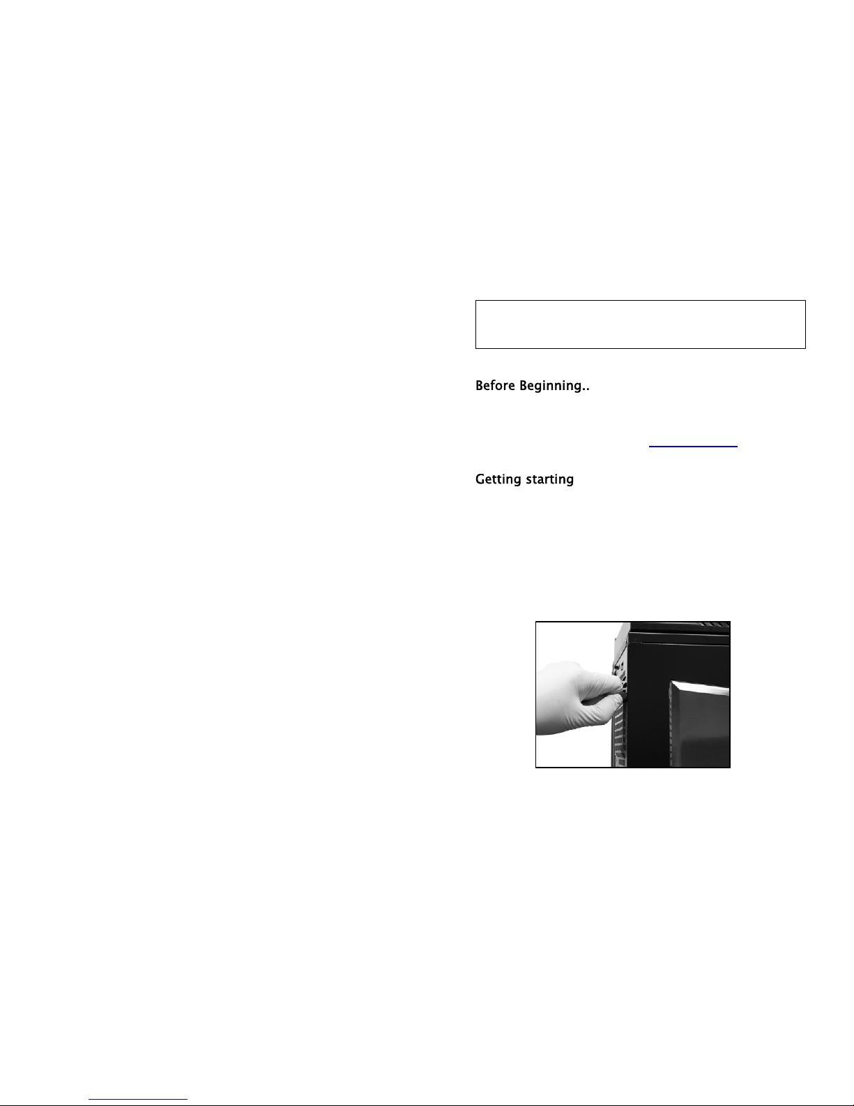
For users building a new system, it is recommended that the side
panels are removed before beginning the installation. The following
steps will outline the steps to remove the top, side panels and the
motherboard tray.
1. Remove the thumb screws securing the side panels.
2. Pull the side panel back, and then lift the panel to remove it.
Opening the side panel
NOTE: CPU, RAM and any peripheral installation are not
included in this manual. Please refer to your motherboard manual
for related mountin
g
instructions and troubleshootin
g
.
NZXT. 5
Please refer to the case interior infrastructure and secure the power
supply at the back of the case by using the screws provided.
1. Match the motherboard form factor ( ATX, M-ATX, Mini-
ATX ) with the holes on the motherboard tray
2. Secure the standoffs onto the holes which match your
motherboard
3. Lay the motherboard onto the standoffs and then
continue to secure the motherboard with the screws
provided.
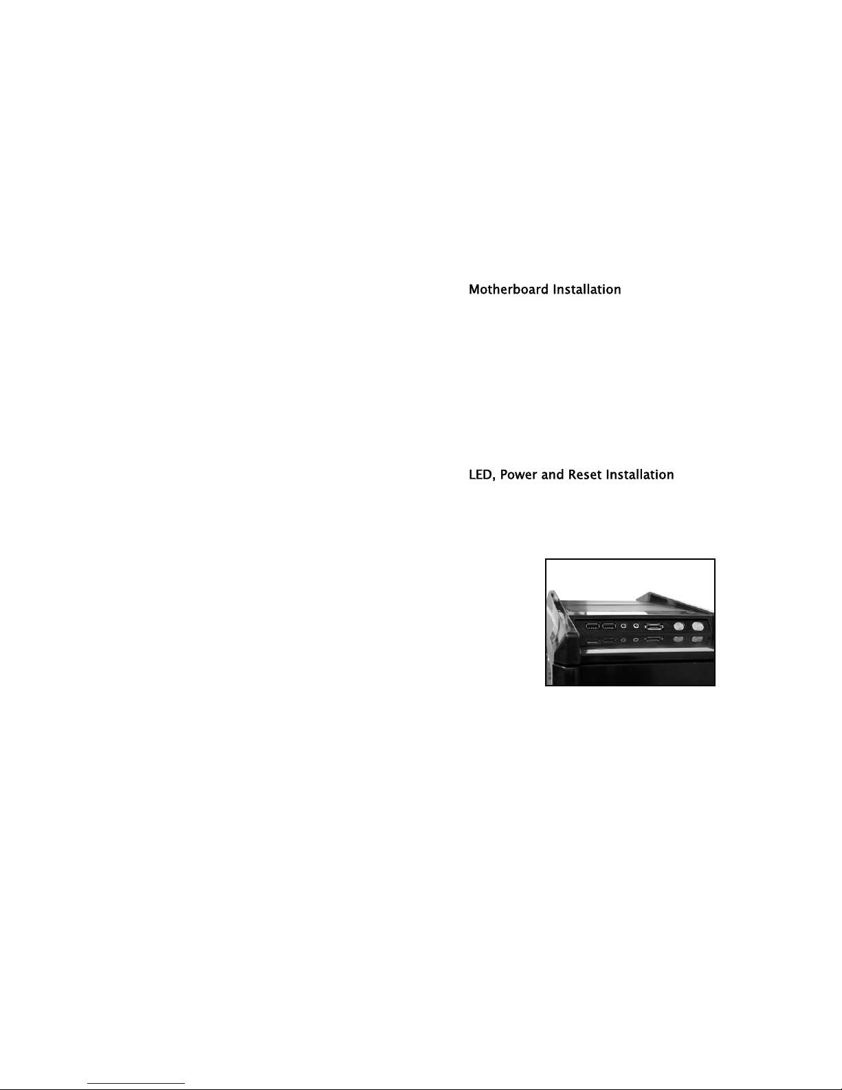
Please refer first to your motherboard manual to locate where the
power switch and reset pins are located. The power and reset
buttons are located at the top of the chassis. The colors following
each instruction designate the color of the wires.
USB, Audio ports, E-SATA, Reset, and Power buttons
1. Connect the reset switch (labeled RESET SW) by
connecting to your motherboard RESET connector. Make
sure you always attach the white wire to ground. (Blue/White
+/-)

NZXT. 6
2. Connect the power switch pin (labeled POWER SW) to the
PWR connector on the motherboard. (Yellow/White +/-)
3. Connect the HDD LED (labeled H.D.D LED) to the
appropriate headers on your motherboard. The HDD LED
located on the front panel should flash green when there is
activity in the hard drive. (Green/White, +/-)
4. Connect the four pin molex leading from the front panel to
activate that two blue LED stripes.
HDD LED location
All White and Black Pin Connectors correspond to
ground.
USB Installation
1. The USB is located of the top on your front panel.
2. Refer to your motherboard manual and match the labels on
the USB port connectors with your motherboard in order to
install.

NZXT. 7
Audio Port Installation
1. Please first refer to your motherboard manual and match the
labels on the audio wires with your motherboard pins.
2. The green input is the speaker input and the pink input is the
microphone input.
Case Pins Signal Description ASUS© Pins
MIC-IN Front Microphone input Signal MIC2
MIC-POWER Front Microphone Power MICPWR
GROUND Front Audio Ground AGND
L-OUT Front Left Channel Audio Signal Line out_L
R-OUT Front Right Channel Audio Signal Line out_R
L-RET Rear Left Channel Audio Signal BLINE Line
out_L
R-RET Rear Right Channel Audio Signal BLINE Line
out_R
ASUS© Motherboard Pin Assignment
Please follow the directions below to install the 5.25” in the top 3
bays of the Tempest:
1. Remove the front panel of the chassis by pulling from the
opening at the bottom of the front panel.
Other NZXT Computer Accessories manuals


