NZXT DUET User manual

Duet
U se r’s m a n u a l


NZXT. 1
Thank you.
Dear Valued Customers,
Thank you for purchasing our product. With the booming of
the gaming market and computer cases, NZXT would like to
differentiate ourselves from other case companies by continuously
providing innovative next generation cases. With every product, we
hope to break more boundaries and limits. I hope you like our
products and look for us again in your future purchases. Any
comments and critiques are always welcome. Thank you again.
After you complete your installation, please come by our community
forums at www.nzxt.com/forum.
Sincerely,
NZXT Team

NZXT. 2
Duet Specifications
Features
Aluminum plated front panel
Small and compact design
Dual positioning, vertical or horizontal depending on home setup
Dual use vents for cooling or expandability, Install dual 120mm fan
capability or dual hard drives
Usb 2.0, Firewire, Intel HD audio and mic support
MOTHERBOARDS: ATX, MICRO ATX
DRIVE BAYS:
2 E XTER N A L 5.25”DRIVE BAYS
1 E XTER N A L 3.5”DRIVE BAYS
3 IN TE R N A L 3.5” H D D D R IV E B A Y S
7 Expansion Slots
COOLING OPTIONS
Front, 1 X 80 mm
Rear, 2 X 80 mm ( Included )
CHASSIS DIMENSIONS (WXDXH): 370 X 455 X 148 mm
CHASSIS MATERIAL: Steel
CHASSIS WEIGHT: 5.0 kg

NZXT. 3
Before Beginning..
For safety issues, it is highly recommended that all users wear
gloves during installation. Also, if you have any questions during
installation, please send an email to service@nzxt.com before
proceeding. Thank you.
Removing the front and side panels
The NZXT Duet front and side panels needs to be removed when
installing devices and fans. Please follow the steps below to remove
the panels.
1. With the panel facing forward, use one hand to hold the case
in place.
2. Place the other hand on the opening at the bottom of the
front panel and pull to detach.
Detaching the front panel
NOTE: CPU, RAM and any peripheral installation are not
included in this manual. Please refer to your motherboard manual
for related mounting instructions and troubleshooting.

NZXT. 4
3. To remove the side panel, use a Phillips (cross shaped)
screw driver and remove the screws on the panel.
4. Pull the panel to remove.
Unscrewing the side panel
Pull the side panel to remove it
Motherboard Installation
The NZXT Duet supports the following motherboard: ATX and
MICRO ATX. The Index for the standoff holes are as follows. (

NZXT. 5
Imprinted on the motherboard tray are serial numbers that match
certain motherboards )
A1~A9 ATX
U1~U9 MICRO ATX
In order to install your motherboard go through the following steps:
1. Lay your case down so you can see the drive cages and the
standoff holes on the motherboard tray.
2. Check your I/O on the motherboard for compatibility with the
standard case I/O plate. If not, replace with the I/O plate that
comes with your motherboard.
Removing the I/O plate
3. Take your motherboard and match the standoff holes.
4. Remembering which standoff holes your motherboard
needs, continue to screw the brass standoffs onto the
motherboard tray. ( Note: If you find that some holes are
unused, this is normal, this case is made to support for many
motherboard sizes )
5. Place your motherboard on top of the brass standoffs and
attach it to the tray using screws provided.
LED, Speaker, Power and Reset Installation

NZXT. 6
Please refer first to your motherboard manual to find where your
power switch and reset pins are located. The colors following each
instruction designate the color of the wires.
1. Connect the reset switch (labeled RESET SW) by
connecting to your motherboard RESET connector. Make
sure you always attach the white wire to ground. The reset
switch is located behind the front panel. (Blue/White +/-)
2. Connect the power switch pin (labeled POWER SW) to the
PWR connector on the motherboard. The power switch is on
the front panel. (Orange/White +/-)
3. Connect the HDD LED (labeled H.D.D LED) to the
appropriate headers on your motherboard. The HDD LED
located on the front panel should flash red when there is
activity in the hard drive. (Red/White, +/-)
4. Connect the 1st power LED (labeled POWER LED) to the
appropriate headers on your motherboard. The Power LED
located on the front panel should power on blue.
(Green/White, +/-)
5. Connect the 2nd power LED, a four pin Molex connector to
the power supply.
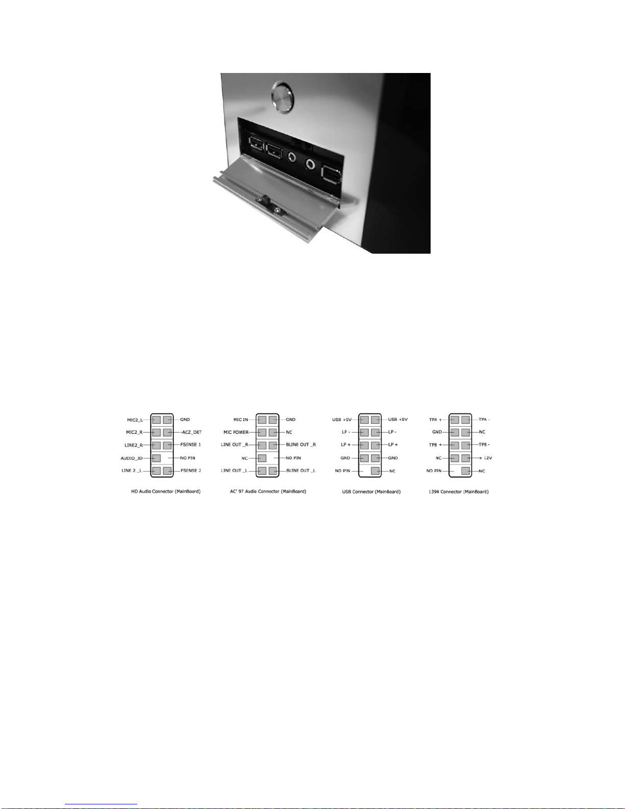
All White and Black Pin Connectors correspond to ground USB &
Audio Installation
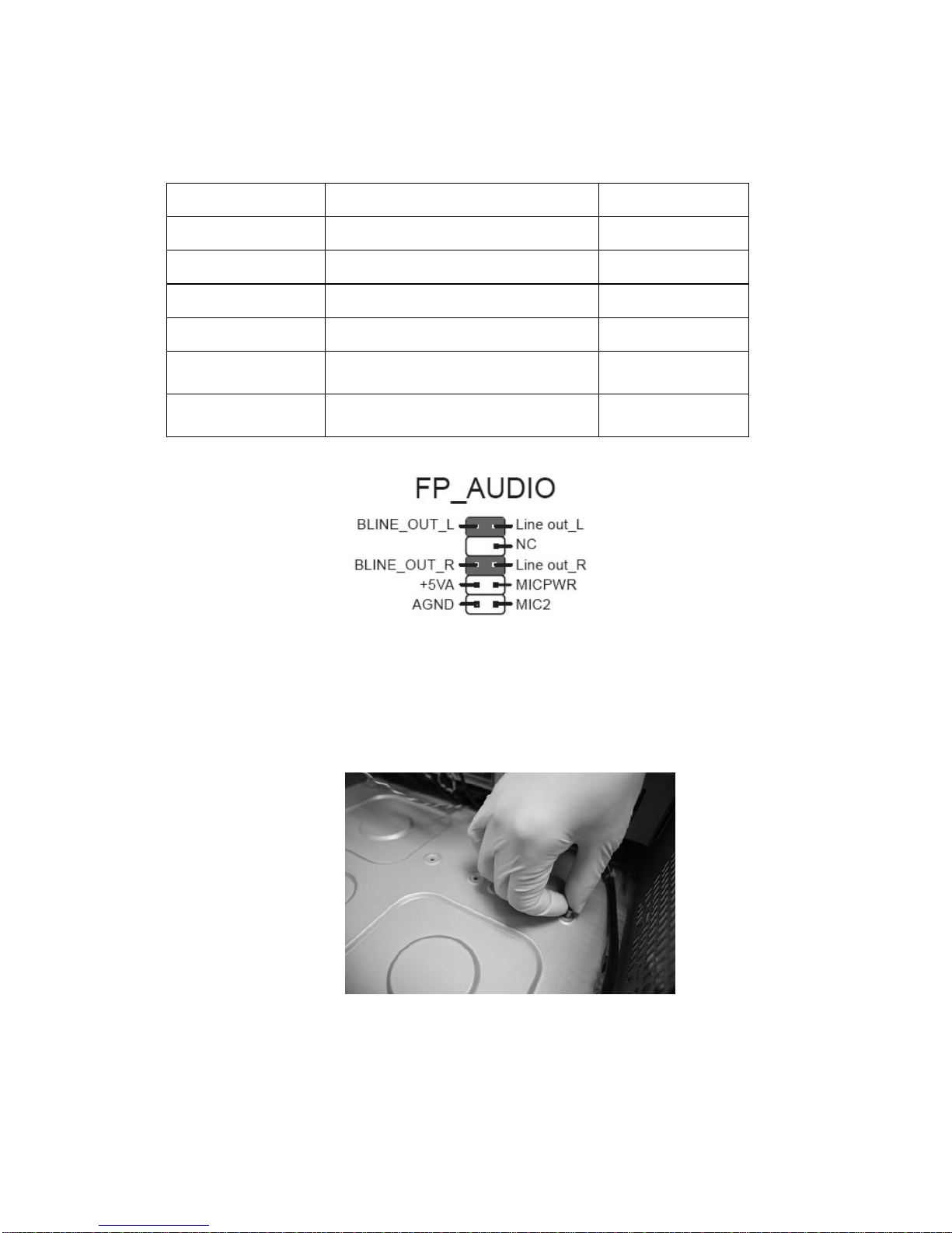
The Reset button is located inside the door

NZXT. 7
USB, Firewire, Audio and Power button are located outside of the door.
USB/Firewire Installation
1. The USB is located of behind the small panel.
2. Refer to your motherboard manual and match the labels on
the USB port connectors with your motherboard in order to
install.
Audio Port Installation
1. Please first refer to your motherboard manual and match the
labels on the audio port connectors on the case with your
motherboard.
2. The green input is the speaker input and the pink input is the
microphone input, these inputs are located behind the small
panel.

NZXT. 8
Case Pins Signal Description ASUS© Pins
MIC-IN
Front Microphone input Signal
MIC2
MIC-POWER
Front Microphone Power
MICPWR
GROUND
Front Audio Ground
AGND
L-OUT
Front Left Channel Audio Signal
Line out_L
R-OUT
Front Right Channel Audio Signal
Line out_R
L-RET
Rear Left Channel Audio Signal
BLINE Line
out_L
R-RET
Rear Right Channel Audio Signal
BLINE Line
out_R
ASUS© Motherboard Pin Assignment
Twist the Copper standoff to attach it onto the motherboard tray

NZXT. 9
After completing the brass standoff installation, attach the motherboard and
secure with a screwdriver
Power Supply Installation
The power supply is installed at the front of the chassis, please
remove with the top panel and front panel before proceeding.
1. Slide in the power from inside the case.

NZXT. 10
2. Secure the power supply with a screwdriver.
3. Connect the power cord.
5 .2 5 ” & 3 .5 ” Drive Installation
External 5.25” Installation
Please follow the directions below to install the 5.25”devices:
1. Detach both the top and front panels.
2. Remove the plastic bay cover.
3. Remove the metallic plate. ( warning –edges are sharp and
can be harmful. Please use gloves and tools to remove )
4. Attach the rails to the two sides of the device. If the rails do
not fit, use screws to manually attach the rails.

NZXT. 11
A ttaching the 5.25” device
U se a screw driver to m anually attach if the 5.25” device is not com patible
A ttaching the 5.25” device

NZXT. 12
D etach the 5.25” plastic cover and com plete installation.
External and Internal 3.5” Installation
Please follow the directions below to install the external 3.5” devices:
1. Remove the top and bottom panels.
2. Remove the plastic bay cover.
3. S lide the 3.5” device into the external slot.
4. Secure the drives with a screw driver.
Secure the panel from the bottom of the case.
P lease follow the directions below to install the internal 3.5” devices:
1. Slide the device in from the inside of the case.

NZXT. 13
2. Secure the drives with a screw driver.
Slide the device in from inside.
Secure the device using a screwdriver.
Dual Use Vents for 120mm and HD Drives
P lease follow the directions below to install the internal 3.5” devices:
1. Line up the fan or hard drive holes with the vent and secure
it from the outside.

NZXT. 14
Secure the device in from the side of the case
Front Fan Installation
1. Begin the installation process by removing the bottom panel.
2. Unscrew the single screws on the fan cage
3. Take the 80mm fan and snap it into the cage.
Remove the cage.

NZXT. 15
Snap the fan onto the cage.
Secure the fan onto the cage with’fan screws ( not included with the case )

NZXT. 16
Support and Service
If you have any more questions or have problems with the
N ZX T product you purchased, please don’t hesitate to contact
service@nzxt.com along with a detailed explanation of your problem
and your proof of purchase. You may inquire about replacement
parts at rma@nzxt.com.
Thank you again for purchasing an NZXT case. If you have
any more comments or questions. Please visit our website or send
us an email.
NZXT Website: www.nzxt.com
Feedback: designer@nzxt.com
Table of contents
Other NZXT Computer Accessories manuals

NZXT
NZXT KRAKEN 240 User manual

NZXT
NZXT Tempest EVO User manual

NZXT
NZXT Lexa S User manual

NZXT
NZXT H7 Flow RGB User manual

NZXT
NZXT noctis 450 User manual

NZXT
NZXT khaos User manual

NZXT
NZXT Sleeved LED Kit User manual

NZXT
NZXT Kraken G10 User manual

NZXT
NZXT BETA Evo User manual

NZXT
NZXT APOLLO User manual
Popular Computer Accessories manuals by other brands

StarTech.com
StarTech.com TB3DOCK2DPPD instruction manual

Vantec
Vantec UGT-PCE430-2C installation guide

Cooler Master
Cooler Master 420W user manual

Logitech
Logitech Premium Notebook Headset Installation

Texas Instruments
Texas Instruments XDS110 user guide

Microchip Technology
Microchip Technology PICkit 3 user guide