O&O NIGHT&DAY 6 Parts list manual

Barriera automatica
Istruzioni per installazione uso e manutenzione
Automatic barrier
Instructions for installation, use and maintenance
Barrière automatique
Instructions d’installation et d’entretien
Automatische Schranke
Installations-, Bedienungs- und Wartungsanleitungen
Barrera automática
Instrucciones para la instalación, el uso y el mantenimiento
ES
DE
FR
EN
IT
UNAC
ASSOCIAZIONE COSTRUTTORI
DI INFISSI MOTORIZZATI EAUTOMATISMI
PER SERRAMENTI IN GENERE
NIGHT&DAY 6
NIGHT&DAY 8


INTRODUZIONE
Il libretto di INSTALLAZIONE USO
E MANUTENZIONE è destinato agli
installatori, agli utilizzatori ed agli
operatori della manutenzione.
Leggere attentamente il libretto prima
di installare il prodotto, utilizzarlo e prima
di eseguire manutenzione ordinaria o
straordinaria.
Le operazioni che, se non effettuate
correttamente, possono presentare
rischi, sono indicate con i simboli:
FOLGORAZIONE SCHIACCIAMENTO
La O&O s.r.l. non è responsabile per
danni arrecati a persone, animali o cose
dovuti ad applicazioni che superano
i limiti indicati nella scheda tecnica
allegata o dall’uso diverso da quello per
cui il prodotto è stato progettato.
INTRODUCTION
The INSTALLATION, USE AND
MAINTENANCE handbook is for
installers, users and maintenance
engineers.
Please read it carefully before
installing the appliance, before using
it and before routine or extraordinary
maintenance work.
Operations that, if not carried out
correctly, can be risky, are indicated with
the following symbols:
ELECTROCUTION CRUSHING
O&O s.r.l. is not liable for injury to
people or animals or damage to things in
the case of applications that exceed the
limits specified on the enclosed technical
data sheet or by a use different from
what the appliance has been designed.
AVANT-PROPOS
Cette notice est destinée aux
installateurs, aux utilisateurs et aux
techniciens chargés de l’entretien.
Lisez attentivement cette notice, avant
d’installer l’automatisme, de l’utiliser
et avant de procéder à son entretien
ordinaire ou extraordinaire.
Les opérations présentant des
risques si elles ne sont pas effectuées
correctement sont signalées avec les
symboles :
ELECTROCUTION ECRASEMENT
La société O&O s.r.l. décline toute
responsabilité en cas de dégâts à des
personnes, animaux ou biens provoqués
par des applications dépassant les
limites prévues dans la fiche technique
jointe ou par un usage différent de celui
pour lequel l’automatisme a été conçu.
INTRODUCCIÓN
El folleto de INSTALACIÓN, USO
Y MANTENIMIENTO se destina a
instaladores, usuarios y operadores de
mantenimiento.
Leer detenidamente el folleto antes de
instalar el producto, utilizarlo y efectuar el
mantenimiento ordinario o extraordinario.
Las operaciones que, si no son
efectuadas correctamente, pueden
conllevar riesgos, vienen indicadas con
los símbolos:
ELECTROCUCIÓN APLASTAMIENTO
La O&O s.r.l. no es responsable de
daños causados a personas, animales o
cosas, debidos a aplicaciones que superen
los límites indicados en la ficha técnica
adjunta o debidos a utilización diferente
de aquella apra la cual el producto fue
proyectado.
EINLEITUNG
Das INSTALLATIONS-, BETRIEBS-
UND WARTUNGSHANDBUCH ist
für die Installateure, Anwender und
Wartungsfachmänner bestimmt.
Das Handbuch ist vor der Installation
des Produkts sowie vor der ordentlichen
und außerordentlichen Wartung sorgfältig
zu lesen.
Wenn die durch folgende Symbole
gekennzeichneten Eingriffe nicht korrekt
durchgeführt werden, kann es zu
Gefahrsituationen kommen:
STROMSCHLAG QUETSCHUNG
Die Firma O&O s.r.l. haftet nicht für Perso-
nen-, Tier- oder Sachschäden, die auf eine
unsachgemäße Anwendung des Produkts
sowie auf das Überschreiten der im tech-
nischen Blatt angegebenen Grenzwerte
zurückzuführen sind.
590
360 60 400
950
1155
SCHEDA TECNICA - TECHNICAL DATA SHEET - FICHE TECHNIQUE - TECHNISCHES BLATT - FICHA TÉCNICA
ALIMENTAZIONE • POWER • ALIMENTATION • STROMVERSORGUNG • ALIMENTACIÓN 230Vac±10% 50/60Hz
MOTORE • MOTOR • MOTEUR • MOTOR • MOTOR 230Vac 900RPM 14uF 0.11kW
POTENZA ASSORBITA • ABSORBED POWER • PUISSANCE ABSORBÉE • LEISTUNGSAUFNAHME • POTENCIAABSORBIDA 300 W
CENTRALINA • CONTROL UNIT • CENTRALE • STEUEREINHEIT • CENTRALITA ARX.246
SICUREZZA ALL’URTO • IMPACT SAFETY • SECURITEAU CHOC • STOSSSICHERHEIT • SEGURIDAD AL CHOQUE Reverser
TEMPO DI APERTURA • OPENING TIME • DELAI D’OUVERTURE • ÖFFNUNGSDAUER • TIEMPO DE APERTURA 8sec. (90°)
LUNGHEZZA BARRA • ARM LENGTH • LONGUEUR DE LA LISSE • BAUMBREITE • LONGITUD BARRA 4÷6.4 m (NIGHT & DAY 6)
6.5÷8 m (NIGHT & DAY 8)
TEMP. DI ESERCIZIO • WORKING TEMP. • TEMPÉRATURE D’EXERCICE • BETRIEBSTEMPERATUR • TEMP. DE OPERACIÓN -30 +60 °C
MANOVRE IN 24h • MANOEUVRES IN 24h • NOMBRE DE MANOEUVRES EN 24h • MANÖVER IN 24 Std • MANIOBRAS EN 24h 2000 (NIGHT & DAY 6)
1000 (NIGHT & DAY 8)
GRADO DI PROTEZIONE • PROTECTION LEVEL • INDICE DE PROTECTION • SCHUTZGRAD • GRADO DE PROTECCIÓN IP 65
DIMENSIONI D’INGOMBRO • OVERALL DIMENSIONS • DIMENSIONS HORS-TOUT • ABMESSUNGEN • MEDIDAS
1
INSTALLAZIONE USO E MANUTENZIONE • INSTALLATION USE AND MAINTENANCE • POSE, MODE D’EMPLOI
ET ENTRETIEN • INSTALLATION, GEBRAUCH UND WARTUNG • INSTALACIÓN USO Y MANTENIMIENTO
GENERALITA’
Labarrieraautomaticaelettromeccanica
NIGHT&DAY6-8 è stata progettata per
gestire passaggi con luce fino a 8 metri
nel rispetto delle normative europee. E’ la
soluzioneideale per lagestione veicolare.
E’adatta ad un utilizzo di tipo industriale.
GENERAL
The automatic electromechanical
barrier NIGHT&DAY6-8 is designed to
control passage openings up to 8 metres
wide in compliance with European
standards. It is the ideal solution for
managing vehicle traffic. It is suitable for
industrial applications.
GENERALITES
Lalisseautomatique électromécanique
NIGHT&DAY6-8 a été conçue pour gérer
les passages jusqu’à une hauteur de
8 m dans le respect de la législation
européenne. Est la solution idéale pour
contrôler le trafic routier. Adaptée à une
utilisation de type industrielle.
ALLGEMEINES
Die automatisch elektromechanische
Schranke
NIGHT&DAY6-8
wurde für
Durch und Einfahrten mit einer Breite
von maximal 8 Metern entwickelt und
entspricht den EU-Normen. Es ist
die ideale Lösung zum Verwalten des
Straßenverkehrs. Für den industriellen
Gebrauch geeignet.
GENERALIDAD
La barrera automática electromecánica
NIGHT&DAY6-8 ha sido diseñada para
controlar pasosconanchodehasta8metros,
según las normas europeas. Es la solución
idealparalagestión deltráficodevehiculos.
Esaptaparaunautilizacióndetipoindustrial.
170

NOTA CAVI • CABE NOTE •CONNEXION CABLES • BEMERKUNG ZU DEN KABEL ANSCHLÜSSEN • NOTA CABLES
2
6
5
7
3
124
300
360
300
400
Ø50
500
600 400
BASAMENTO • BASE • BASE • BASIS • BASE
4
DISPOSIZIONE • LAYOUT •DISPOSITION • DISPOSITION
DISPOSICIÓN
3
Linea Monofase - Single-phase line - Ligne monophasée
Einphasenleitung - Línea monofásica 2 x 1,5 + T
Fotocellula Trasmett. - Transmitter photocell - Photocellule émettrice
Senderfotozelle - Fotocélula transmisor 2 x 0,5
Fotocellula Ricev. - Receiver photocell - Photocellule réceptrice
Empfängerfotozelle - Fotocélula receptor 4 x 0,5
Lampeggiante - Flashing light - Clignotant
Blinkleuchte - Indicador intermitente 2 x 0,5
Selettore a chiave - Key selector - Sélecteur à clé
Schlüsselschalter - Selector de llave 3 x 0,5
Ricevente - Receiver - Récepteur - Empfänger - Receptor 4 x 0,5
Antenna - Antenna - Antenne - Antenne - Antena RG58
Spirale magnetica - Magnetic coil - Spirale magnétique
Magnetspirale - Espiral magnética
5
6
3
1
2
4
6
7
Barriera DESTRA
RIGHT barrier
Lisse DROITE
RECHTE Schranke
Barrera DERECHA
Barriera SINISTRA
LEFT barrier
Lisse GAUCHE
LINKE Schranke
Barrera IZQUIERDA

FISSAGGIO STRUTTURA • FIXING THE STRUCTURE • FIXATION STRUCTURE • STRUKTURBEFESTIGUNG
FIJACIÓN ESTRUCTURA
5
CH 19
Non fornito
Not supplied
Non fourni
Nicht mitgeliefert
No suministrada
CH 13
6
M10 - DIN 985
Ø10 - UNI 6592
Ø8 - UNI 6592
M8x20 - UNI 5739
M6x20
M8 - DIN 985
Ø8 - UNI 6592
M6x20
Ø10 - UNI6592
M10 - DIN 985
M10x80 - UNI 5737
Ø10 - UNI6592
16x60 - UNI6873
Ø10 - UNI 6592
M10x25 - UNI 5739
ASSEMBLAGGIO BARRA • MOUNTING THEARM • ASSEMBLAGE LISSE • BAUMZUSAMMENBAU • MONTAJE BARRA
Rimuovere la pellicola protettiva
Remove the protective film
Retirer le film protecteur
Entfernen Sie die Schutzfilm
Quite la película protectora
SERRARE 50 Nm
TIGHTEN 50 Nm
SERRER 50 Nm
FESTZIEHEN 50 Nm
APRETAR 50 Nm

INSTALLARE LA BARRA • INSTALL THE ARM • INSTALLEZ LA LISSE • INSTALLATION DES BAUMS • INSTALAR LA BARRA
7
MANOVRA MANUALE • MANUAL MANOEUVRE • MANOEUVRE MANUELLE • MANUELLES MANÖVRIEREN • MANIOBRA
MANUAL
8
• Prima di effettuare qualsiasi
interventosull’impiantotogliere
l’alimentazione elettrica.
• Alwaysdisconnecttheelectricity
before attempting any work on
the system.
• Coupez l’arrivée de courant
électrique avant toute
intervention sur l’automatisme.
• Vor jeglichen Eingriffen an der
AnlageistdieStromversorgung
zu unterbrechen.
• Antes de cualquier operación
en la instalación, cortar la
alimentación eléctrica.
Sbloccaggio barriera
Releasing the barrier
Déblocage de la lisse
Schranke entsperren
Desbloqueo barrera
• Collegare elettricamente la centralina
• Infilare un pezzo di barra di circa 1 metro nel portabarra
• Dare il comando “START” per posizionare il portabarra in posizione orizzontale
• Tirare la barra verso il basso per aiutare il riduttore a vincere la forza della molla pretarata
• Installare la barra e regolare il portabarra
•Electrically connect the control unit
•Insert about 1 metre of the arm in the holder
•Give the “START” command to position the arm holder horizontally
•Pull the arm down to help the reducer counteract the force of the pre-calibrated spring
• Install the arm and adjust the holder
• Branchez le groupe à l’alimentation électrique
• Enfilez une longueur de lisse de 1 mètre environ dans le support de lisse
• Actionnez la commande “START” pour placer le support de lisse en position horizontale
• Tirez la lisse vers le bas de telle sorte que le réducteur puisse exercer une force supérieure
à la résistance opposée par le ressort préréglé;
• Installez la lisse et réglez le support de lisse.
• Conectar eléctricamente la centralita
•Insertar un trozo de barra de aproximadamente 1 metro en el portabarra
•Dar el comando “START” para colocar el portabarra en posición horizontal
•Tirar de la barra hacia abajo para ayudar al reductor a vencer la fuerza del muelle calibrado
de antemano
• Instalar la barra y ajustar el portabarra
• Die Steuereinheit elektrisch anschließen
• Die Schranke mit einer Länge von ca. 1 m in die Schrankenhalterung einschieben.
• Den Befehl „START“ eingeben, um Die Schrankenhalterung in die waagrechte Position
bringen
• Die Schranke nach unten ziehen, damit das Untersetzungsgetriebe die Kraft der vorge-
eichten Feder leichter überwinden kann.
• Die Schranke montieren und die Schrankenhalterung einstellen
“START”
PER ALLINEARE LA BARRAALLA PAVIMENTAZIONE STRADALE AGIRE SUL PORTABARRA
REGOLABILE. NON MODIFICARE LA POSIZIONE DEI FINECORSA GIA’ PRETARATI
POUR ALIGNER LA LISSE PAR RAPPORT À LA CHAUSSÉE, INTERVENIR SUR LE SUPPORT
DE LISSE RÉGLABLE. NE PAS MODIFIER LA POSITION DES FINS DE COURSE PRÉRÉGLÉES
ZUM AUSRICHTEN DER SCHRANKE MIT DEM STRASSEBELAG IST AUF DIE VERSTELLBARE
SCHRANKENHALTERUNG EINZUWIRKEN.
DIE POSITION DER BEREITS VORGEEICHTEN ENDSCHALTER NICHT ÄNDERN
PARAALINEAR LA BARRA CON LA CALZADA, ACTUAR SOBRE EL PORTABARRA REGULABLE.
NO MODIFICAR LA POSICIÓN DE LOS FINALES DE CARRERA YA PREAJUSTADOS
Portabarra regolabile
Adjustable arm holder
Support de lisse réglable
Verstellbare Schrankenhalterung
portabarra regulable
USE THE ADJUSTABLE ARM HOLDER TOALIGN THE ARM WITH THE ROAD. DO NOT CHANGE
THE POSITION OF THE LIMIT SWITCHES AS THEY ARE ALREADY ADJUSTED

CH19
EQUILIBRATURA DELLA BARRA • BALANCING THE ARM • EQUILIBRAGE DE LA LISSE • AUSBILANCIERUNG DES BAUMES
EQUILIBRADO DE LA BARRA
9
45°
Non appesantire la barra applicando altri accessori
Do not weigh the arm down by applying other accessories
Ne pas alourdire la lisse en y appliqant d’autres accessoires
Den Baum nicht durch die Installation von weiterem Zubehör belasten
No aumentar el peso de la barra poniendo otros accesorios
Controllare che la barra sia equilibrata a 45°
Check that the arm is balanced at 45°
S’assurer que la lisse est équilibrée à 45°
Überprüfen, dass die Schranke in der 45°-Stellung ausgeglichen ist.
Comprobar que la barra esté equilibrada a 45°
Taratura molle
Springs calibration
NIGHT&DAY 6 NIGHT&DAY 8
4000 4500 5000 5500 6000 6500 7000 7500 8000
BL-LARGE
Molla
Spring Ø 7.5 + 7.5 7.5 + 7.5 9 9 9 9 + 9 9 + 9 9 + 9.5 9 + 9.5
A (mm) 128 128 128 98 58 128 128 128 118
BL-LARGE
+ PP
Molla
Spring Ø 7.5 + 7.5 7.5 + 7.5 9 9 7.5 + 9 9 + 9 9 + 9 9 + 9 9.5 + 9.5
A (mm) 128 103 113 78 108 128 118 98 128
BL-LARGE
+ KIT-GOM
Molla
Spring Ø 7.5 + 7.5 7.5 + 7.5 9 7.5 + 9 7.5 + 9 9 + 9 9 + 9 9 + 9 9.5 + 9.5
A (mm) 128 78 88 113 78 118 98 78 118
BL-LARGE
+ KIT-GOM
+ PP
Molla
Spring Ø 7.5 + 7.5 9 9 7.5 + 9 9 + 9 9 + 9 9 + 9 9.5 + 9.5 9.5 + 9.5
A (mm) 108 103 68 103 128 118 98 118 113
BL-LARGE
+ KIT-LIGHT
Molla
Spring Ø 7.5 + 7.5 7.5 + 7.5 7.5 + 7.5 7.5 + 9 7.5 + 9 9 + 9 9 + 9 9 + 9 9.5 + 9.5
A (mm) 128 113 68 128 108 128 118 98 128
BL-LARGE
+ KIT-LIGHT
+ PP
Molla
Spring Ø 7.5 + 7.5 9 9 9 7.5 + 9 9 + 9 9 + 9 9 + 9 9.5 + 9.5
A (mm) 128 128 98 68 98 128 118 98 128
BL-LARGE
+ KIT-LIGHT
+ KIT-GOM
Molla
Spring Ø 9 9 9 7.5 + 9 9 + 9 9 + 9 9 + 9 9.5 + 9.5 9.5 + 9.5
A (mm) 128 113 78 108 128 108 98 118 113
BL-LARGE
+ KIT-LIGHT
+ KIT-GOM
+ PP
Molla
Spring Ø 9 9 7.5 + 9 7.5 + 9 9 + 9 9 + 9 9.5 + 9.5 9.5 + 9.5 9.5 + 9.5
A (mm) 128 98 118 88 128 98 128 128 118
BL-LARGE
+ RS/A
Molla
Spring Ø 9 9 7.5 + 9 7.5 + 9 9 + 9
A (mm) 128 98 118 83 108
BL-LARGE
+ RS/A
+ PP
Molla
Spring Ø 9 9 7.5 + 9 9 + 9 9 + 9
A (mm) 118 78 98 128 98
BL-LARGE
+ RS/A
+ KIT-LIGHT
Molla
Spring Ø 9 9 7.5 + 9 9 + 9 9 + 9
A (mm) 128 88 108 128 108
BL-LARGE
+ RS/A
+ KIT-LIGHT
+ PP
Molla
Spring Ø 9 7.5 + 9 7.5 + 9 9 + 9 9 + 9
A (mm) 108 128 93 128 98
precarico
preload
A
FINECORSA SUPPLEMENTARI
ADDITIONAL LIMIT SWITCH
MICRO-INTERRUPTEUR ADDITIONEL
ENDSCHALTER ZUSÄTZLICH
FIN DE CARRERAADICIONAL
10
OPTIONAL
MICROSWITCH
BL-LARGE RS/A
PP
KIT-LIGHT
KIT-GOM 96
118

USE
• It is essential to follow the
instructions given in the enclosed
“GENERALINSTRUCTIONSFOR
SAFETY” sheet.
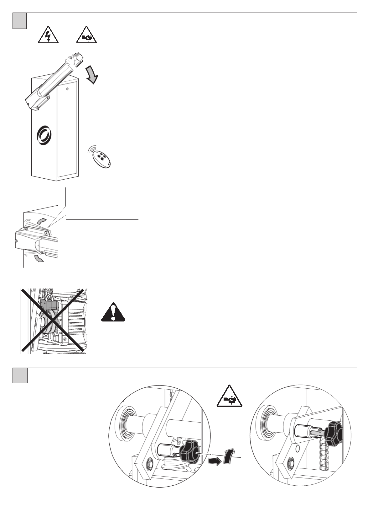
• Inthecaseofamanualmanoeuvre,
follow the indications described in
point 8.
UTILISATION
• Suivez scrupuleusement les
prescriptionsreportéessurlafeuille
jointe “REGLESGENERALESDE
SECURITE”.
• En cas de manœuvre manuelle,
suivez les indications décrites au
paragraphe 8.
ROUTINE
MAINTENANCE
(EVERY 6 MONTHS)
• Maintenance must be carried out
by qualified personnel only.
• Check the condition of the barrier
structure.
• Check tightness of the arm.
• Check the condition of the spring,
chain and relative anchorings.
• Check arm balance.
• Check that at the end of travel the
arm is horizontal and/or vertical
• Check operation of the emergency
manoeuvre.
• Check operation of the control unit
and safety devices.
ENTRETIEN
ORDINAIRE
(TOUS LES 6 MOIS)
• L’entretien doit être effectué
seulement par un personnel
qualifié.
• Contrôlez la structure de la lisse.
• Contrôlez le serrage de la lisse.
• Contrôlez l’état du ressort,
de la chaîne et des fixations
correspondantes.
• Contrôlez l’équilibrage de la lisse.
• Contrôlez l’horizontalité et/ou
la verticalité de la lisse en fin de
course.
• Vérifiez le fonctionnement de la
manœuvre d’urgence.
• Vérifiez le fonctionnement de
la centrale et des dispositifs de
sécurité.
MANTENIMIENTO
ORDINARIO
(CADA 6 MESES)
• Elmantenimientodebeserefectuado
sólo por personal cualificado.
• Comprobar el estado de la estructura
de la barrera.
• Comprobar el estado del apriete de
la barra.
• Comprobarelestadodelmuelle,dela
cadenaycorrespondientesfijaciones.
• Comprobar el equilibrio de la barra.
• Comprobar que a tope de carrera la
barra quede horizontal y/o vertical
• Verificar el funcionamiento de la
maniobra de emergencia.
• Verificar el funcionamiento de la
centralita y de los dispositivos de
seguridad.
ORDENTLICHE
WARTUNG
(ALLE 6 MONATE)
• Die Wartung hat ausschließlich durch
Fachpersonal zu erfolgen.
• Zustand der Schrankenstruktur
überprüfen.
• Kontrollieren,dass der Baumkorrekt
befetsigt ist.
• Zustand der Feder, der Kette und
der entsprechenden Verankerungen
überprüfen.
• Ausbilancierung des Baumes
überprüfen.
• Kontrollieren, dass der Baum am
Endanschlag waagerecht oder
senkrecht ist.
• FunktionstüchtigkeitdesNotmanövers
überprüfen..
•FunktionstüchtigkeitderSteuereinheit
und der Sicherheitsvorrichtungen
überprüfen.
MANUTENZIONE
ORDINARIA
(OGNI 6 MESI)
• La manutenzione deve essere
eseguita solo da personale
qualificato.
• Controllare lo stato della struttura
della barriera.
• Controllare lo stato del serraggio
barra.
• Controllarelostatodellamolla,della
catena e dei relativi ancoraggi.
• Controllare l’equilibratura della
barra.
• Controllarecheafinecorsalabarra
sia orizzontale e/o verticale
• Verificare il funzionamento della
manovra di emergenza.
• Verificare il funzionamento della
centralina e dei dispositivi di
sicurezza.
Cod. 035340 Rev.002 del 08/09/10
BETRIEB
• Die in dem beigestellten Blatt
“ALLGEMEINE SICHERHEITSVOR-
SCHRIFTEN”
enthaltenen Anleitungen
sind strikt zu befolgen.
• Beim manuellen Manövrieren sind
die unter Punkt 8beschriebenen
Anleitungen zu beachten.
USO
• Seguirtajantementelasindicaciones
presentadas en la hoja adjunta
“ADVERTENCIAS GENERALES
PARA LA SEGURIDAD”.
• En caso de maniobra manual seguir
las indicaciones del punto 8.
USO
• Seguire tassativamente le
indicazioni contenute nel
foglio allegato “AVVERTENZE
GENERALIPERLASICUREZZA”.
• Incasodimanovramanualeseguire
le indicazioni descritte al punto 8.
SICUREZZA GENERALE
• Si consiglia, per ragioni di
sicurezza e nel rispetto delle
normative vigenti, di utilizzare
l’apposita centralina di comando
O&O.
• L’installazione deve essere
eseguitaseguendoleprescrizioni
contenute nel foglio allegato
“AVVERTENZE GENERALI PER
LA SICUREZZA”.
• I collegamenti elettrici devono
essere effettuati nel rispetto delle
disposizioni legislative vigenti.
• L’installatore deve istruire
l’utilizzatore sul corretto
funzionamento dell’automatismo,
sulla manovra manuale
d’emergenza e sui possibili rischi
durante il funzionamento.
• Eseguire l’analisi dei rischi
prendendo opportuni
provvedimentipereliminarli,come
prescrittodalladirettiva macchine
2006/42/CEE, installando i
dispositivi di sicurezza.
• Prima di effettuare qualsiasi
intervento sull’impianto togliere
l’alimentazioneelettricamediante
un sezionatore lucchettabile.
GENERAL SAFETY
• For safety reasons and to
comply with current standards,
we recommend using the O&O
control unit.
• To install follow the instructions
givenintheenclosed“GENERAL
INSTRUCTIONS FOR SAFETY”
sheet.
• Allelectricalconnectionsmustbe
done in compliance with current
laws.
• The installer must instruct
the user on how to use the
automatism correctly, on the
manual emergency manoeuvre
and on the possible risks during
operation.
• Analyse the risks and take all the
appropriatemeasurestoeliminate
them, as prescribed by the
EEC machine directive 2006/42,
installing the safety devices.
• Always disconnect the electricity
before attempting any work on
thesystem with alockablecut-off
switch.
SECURITE GENERALE
• Pour des raisons de sécurité et
d’observation de la législation en
vigueur,ilest conseillé d’utiliser la
centrale de commande O&O.
• La pose doit s’effectuer selon
les prescriptions reportées
sur la feuille jointe “REGLES
GENERALES DE SECURITE”.
• Les branchements électriques
doivent être conformes à la
législationenvigueurenlamatière.
• L’installateur doit informer
l’utilisateur sur le fonctionnement
del’automatisme,surla manœuvre
manuelle d’arrêt d’urgence et sur
lesrisquesliésaufonctionnement.
• L’analyse des risques implique
la mise sur pied de mesures
destinéesàéliminerlesditsrisques
comme le prévoit la directive
machines 2006/42/CEE, en
installantlesdispositifsdesécurité.
• Coupez l’arrivée de courant
électriqueavanttouteintervention
sur l’automatisme avec un
interrupteur verrouillable.
ALLGEMEINE SICHERHEIT
•
Aus Sicherheitsgründen und zum
Einhalten der anwendbaren Gesetze
wird empfohlen, die spezielle
SteuereinheitvonO&Ozuverwenden.
• Bei der Installation sind die im
beiliegenden Blatt “ALLGEMEINE
SICHERHEITSHINWEISE”
enthaltenen Vorschriften zu befolgen.
• BeimAnschlussandieStromversorgung
sind die geltenden Gesetze zu
befolgen.
• Der Installateur hat den Anwender
bezüglich des korrekten Betriebs
des Automatismus, der manuellen
BedienungbeiStörungenundNotfällen
sowie bezüglich der möglichen
Gefahren während des Betriebs zu
unterrichten.
• Es ist eine Gefahrenanalyse
durchzuführen und es sind geeignete
Maßnahmen zum Eliminieren der
Gefahren zu treffen, wie von der
Maschinenrichtlinie 2006/42/EWG
vorgeschrieben,wobeiauchderSchub
einreguliert und die erforderlichen
Sicherheitsvorrichtungen installiert
werden müssen.
• Vor jeglichen EingriffenanderAnlage
ist die Stromversorgung mit einen
Schlüssel-Trennschalter zu unterbrechen.
SEGURIDAD GENERAL
• Por razones de seguridad y para
respetar las normas vigentes se
aconseja utilizar la correspondiente
centralita de control O&O.
• La instalación debe efectuarse
siguiendo las prescripciones
presentadas en la hoja
adjunta“ADVERTENCIAS
GENERALES PARA LA
SEGURIDAD”.
• Las conexiones eléctricas deben
efectuarse cumpliendo las
disposiciones de ley vigentes.
• Elinstaladordebeinstruiralusuario
sobre el funcionamiento correcto
del automatismo, maniobra manual
de emergencia y posibles riesgos
durante el funcionamiento.
• Efectuar el análisis de riesgos
tomando las oportunas medidas
para eliminarlos, como prescrito
por la directiva máquina 2006/42/
CEE, instalando los dispositivos de
seguridad.
• Antes de cualquier operación en la
instalación, cortar la alimentación
eléctrica con un interruptor
seccionador.
O&O s.r.l. - Via Europa, 2 - 42015 CORREGGIO (R.E.) Italy
tel. +39 (0)522 740111 - fax +39 (0)522 631290
Società soggetta ad attività di direzione e coordinamento di SOMFY S.A.
Company subject to management and coordination activities by SOMFY S.A.
This manual suits for next models
1
Table of contents
Other O&O Other manuals