Oasis Berco Oasis Linear Duo Setup guide

Space to think
www.oasis-berco.com
PODS (Duo, Small Team & Large Team)
GLAZED REAR WALL
SAFETY AND INSTALLATION
INSTRUCTIONS
Updated March, 2019

Space to think
www.oasis-berco.com
Oasis Berco Installation, Operating & Safety Instructions
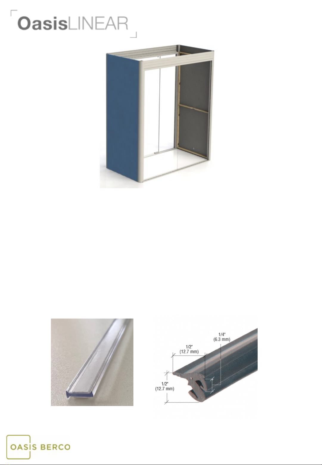
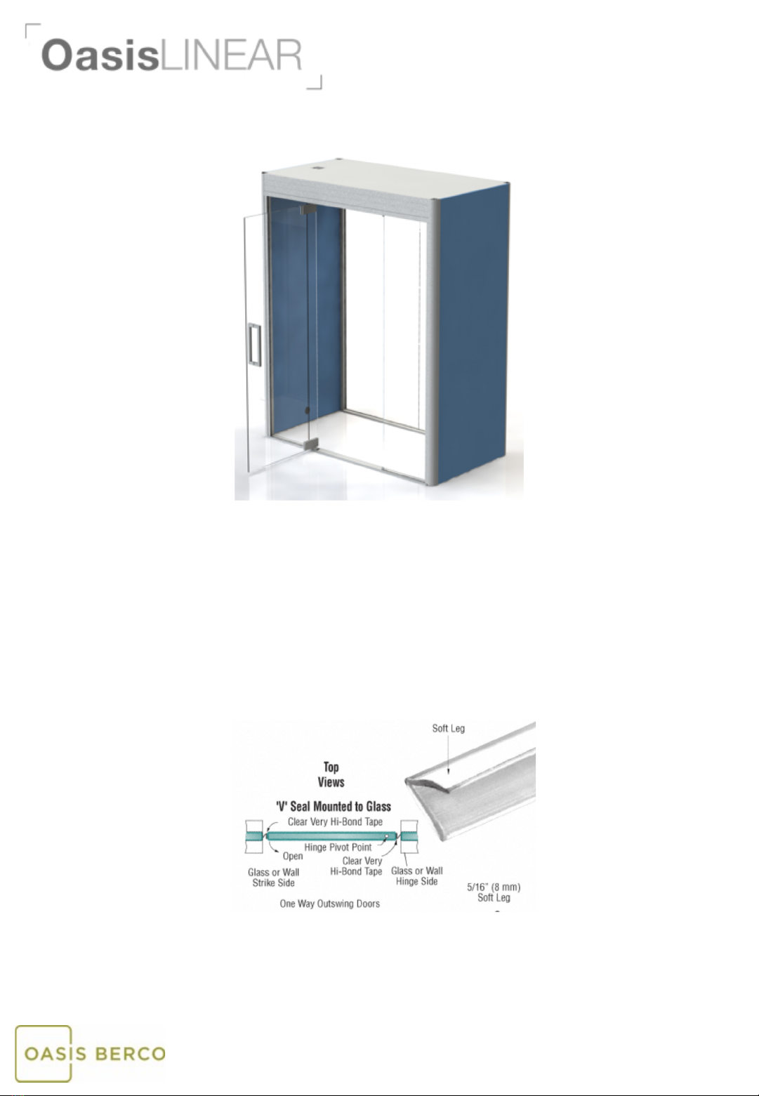
Linear & Soft Pod, Booth and Hub
• All Oasis Berco products are intended for commercial use.
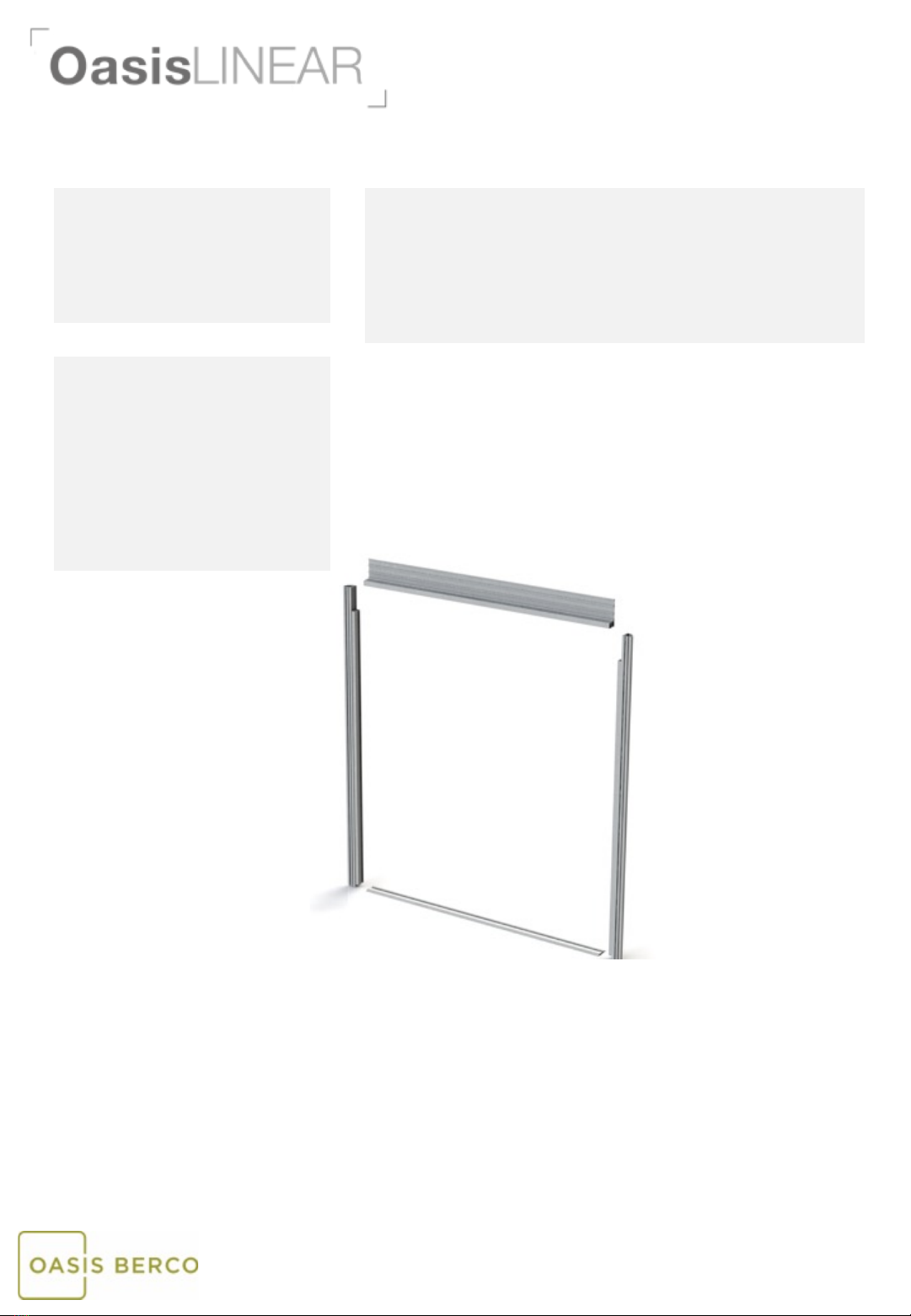
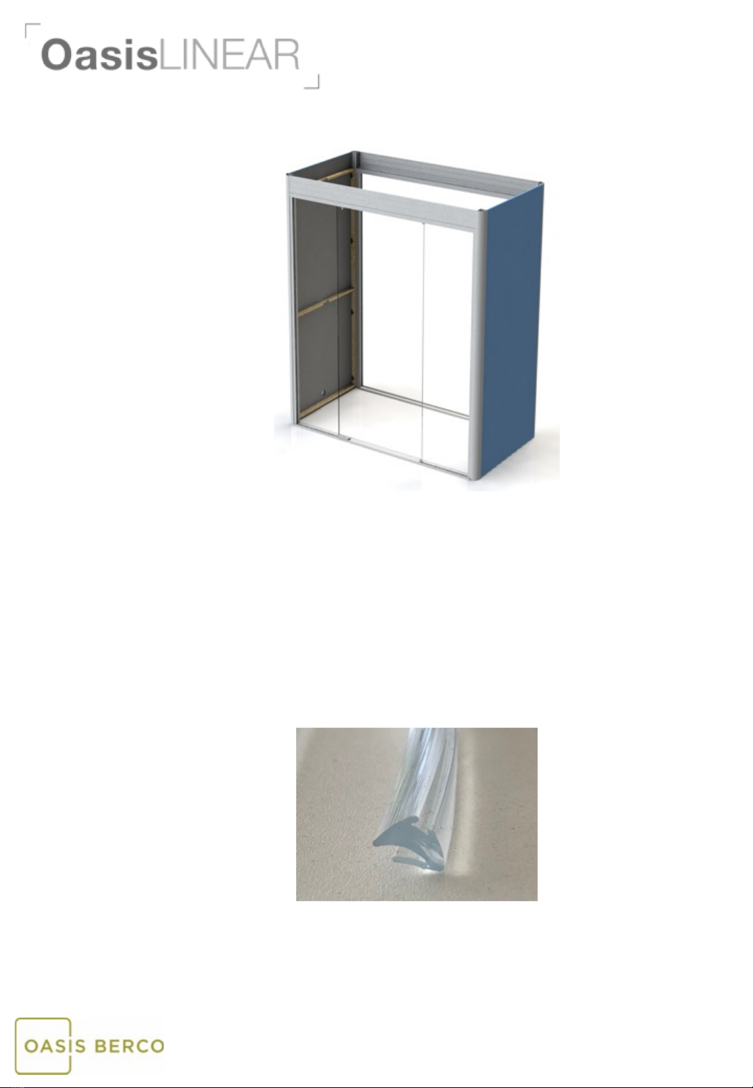
• Please note that specific installation drawings and instructions are provided at the end of this
document.
• WARNING Risk of injury –Maximum Load on Table Surface is 200 pounds evenly distributed
• DRY LOCATIONS ONLY
IMPORTANT SAFETY INSTRUCTIONS
When using an electrical furnishing, basic precautions should always be followed, including the
following: Read all instructions before using this Oasis Berco furnishing.
DANGER –To reduce the risk of electric shock:
1. Always unplug this furnishing from the electrical outlet before cleaning.
WARNING –To reduce the risk of burns, fire, electric shock, or injury to persons:
1. Unplug from outlet before putting on or taking off parts.
2. Close supervision is necessary when this furnishing is used by, or near children, invalids, or disabled
persons.
3. Use this furnishing only for its intended use as described in these instructions. Do not use
attachments not recommended by the manufacturer.
4. Never operate this furnishing if it has a damaged cord or plug, if it is not working properly, if it has
been dropped or damaged, or dropped into water. Return the furnishing to a service center for
examination and repair.
5. Keep the cord away from heated surfaces.
6. Never operate the furnishing with the air openings blocked. Keep the air openings free of lint, hair,
and the like.
7. Never drop or insert any object into any opening.
8. Do not use outdoors.
9. Do not operate where aerosol (spray) products are being used or where oxygen is being
administered.
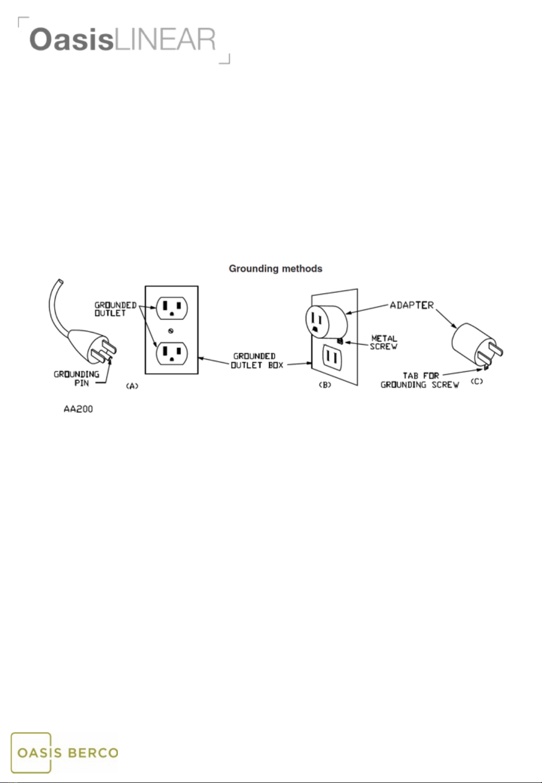
10. WARNING: Risk of Electric Shock –Connect this furnishing to a properly grounded outlet only. See
Grounding Instructions below.
11. For loading always put heavier items at the bottom and not near the top in order to help prevent
the possibility of the furnishing tipping over.
12. WARNING Risk of injury –Maximum Load on Table Work Surface is 200 pounds evenly distributed.
SAVE THESE INSTRUCTIONS

Space to think
www.oasis-berco.com
GROUNDING INSTRUCTIONS
This product is for use on a nominal 120-volt circuit and has a grounding plug that looks like
the plug illustrated in the sketch below. Make sure that the product is connected to an outlet
having the same configuration as the plug. No adapter should be used with this product.

•3.5MM Allen Wrench
•Torx – 30 driver bit
•#2 phillips driver bit
•Utility Knife
•Lint Roller
•White Gloves
1. Read instructions and check that all parts are accounted for
before you start building.
2. Begin assembly as close to final product location as possible.
3. Additional assembly instructions may be required depending on
specification of product ordered.
4. Read all Operating & Safety instructions before using this Oasis
Berco furnishing.
Step 1
A. White gloves are recommended during installation to avoid dirt or grease transfer
to the Oasis unit.
B. Start by assembling the rear glazed wall. This is shipped “knocked down” due to
the size.
C. The parts you need include: left post, right post, base rail and top rail.
D. Secure the base rail (threshold) to the posts first using 4 - #8 x 2 ½” self tapping
screws. The radius portion of the post should be facing outside the Pod.
E. Secure the top rail to the posts using 2 - #8 x 2 ½” self tapping screws. The flat face
of the top rail should be facing the outside of the Pod.
F. Secure header angle brackets to side posts using 2 – ¼ -20 x 2” machine screws.
Space to think
Tools needed for assembly: Before you start:
www.oasis-berco.com
Hardware/Accessory Kit:
•12 -#8 x 2 ½” self tapping screws
•12 – ¼-20 x 2” machine screws
•4 -#8 x 1 ½” wood screws
•4 -#8 x ¾” wood screws
•Double Handle Glass Suction Cups –
2 per order
•Glass Door Handle
•Glazing Seal
•“I” Gasket
•“V” Seal
•Alcohol Wipes

Step 2
A. Install the side walls. Place the panel with the grommet hole in the bottom to the
side where you want the power cord to exit.
B. Secure each wall to the corner posts using 8 – ¼ x 20 x 2” machine screws.
C. Use Allen wrench to adjust the glides in each of the corners to level the unit.
Space to think
www.oasis-berco.com
Step 3
A. The front glazed wall/door assembly will be supplied knocked down just like the
rear wall assembly.
B. The parts you need include: left post, right post, base rail and top rail.
C. Secure the base rail (threshold) to the posts first using 4 - #8 x 2 ½” self tapping
screws. The radius portion of the post should be facing outside the Pod.
D. Secure the top rail to the posts using 2 - #8 x 2 ½” self tapping screws. The flat face
of the top rail should be facing the outside of the Pod.
E. Secure header angle brackets to side posts using 2 – ¼ -20 x 2” screws.

Space to think
www.oasis-berco.com
Step 4
A. Make sure the structure is square and all panels line up with the top posts and
frame headers. Tighten all bolts once all is square.
B. Install the door side glass panels into position. Be careful not to set the glass on a
corner or it will chip or break.
i. Lift the left side glass panel into the top groove and then set down into
the base groove. (Use double handle glass suction cups provided.)
ii. Repeat for the right side glass panel.
iii. Push the side glass panels in towards the hinge plates and door stop
where the door glass will be installed (Step 9).
C. Make sure the frame and glass panels are square. Push the glazing seal (see picture
below) around the top and sides to secure the panels in place. You will need to cut
seal to correct length. This gasket is push in place and will form a tight seal to hold
the glass panel.
Glazing Seal

Space to think
www.oasis-berco.com
Step 5
A. Install the rear glass panels. Be careful not to set the glass on a corner or it will
chip or break.
i. You can install from either inside or outside the Pod.
ii. Lift one panel into the top groove and slide down into bottom groove.
iii. Clean the edge of the glass facing the center of the Pod.
iv. Install the “I” gasket (see picture below) by removing the adhesive strip
from one side and attaching it to the glass.
v. Lift the second panel into the top groove and slide down into the bottom
groove.
vi. Clean the edge of the glass facing the center of the Pod with alcohol wipe.
vii. Remove the adhesive strip from the “I” gasket and press the two pieces of
glass together.
B. Center the combined glass panels in the opening.
C. Push the glazing seal (see picture below) around the top, and sides to secure the
panels in place. You will need to cut seal to correct length. This gasket is push in
place and will form a tight seal to hold the glass panel. It should be installed on the
inside of the Pod.
Glazing Seal
“I” Gasket

Space to think
www.oasis-berco.com
Step 6
A. The ceiling panel is supplied with the electrical pre-installed.
B. Lift the ceiling panel into position from the top with the fan unit to the rear of the
Pod. Before you set it in place, make sure the cords mentioned in “C” and “D”
below are hanging into the unit.
C. Drop the power cable down the inside of the booth and through the cable outlet so
it exits out the base of the unit. The power cord can run down the left or the right
side of the unit.
D. Drop the motion sensor down the front corner of the booth closest to the hinge
side of the door. This will be attached after the acoustical panels are installed.
E. If optional sofas include integrated power, drop an extension cord down the inside
of the booth wall(s). The extension cord(s) will be connected to the sofa later in the
installation.
F. Connect the power and make sure the light & fan turn off/on via the sensor (the
light intensity and fan speed can be changed by adjusting the dials on the ceiling
panel).
i. If the light and fan do not work, first check all connections on the ceiling
panel.
ii. Reset the motion sensor (See Step 10, E).
iii. See Electrical Troubleshoot section at the end of this document.
iv. If all connections are secure, please contact Oasis Berco at 888-772-4788
and ask for Dave Dunn or James Holborow in Engineering.
G. Secure the ceiling panel using 4 - #8 x 1 ½” wood screws from the hardware kit.
Evenly space 2 screws on each side wall and screw up from the inside of the Pod
into the ceiling.

Step 7
Space to think
www.oasis-berco.com
A. To finish the ceiling lift the white ceiling cover into position with the air inlet towards
the left of the booth.
B. Attach the fan cover over the air inlet and secure with 4 - #8 x ¾” wood screws from
the hardware kit.
A. Install the internal fabric panels. Both full size panels are interchangeable so it does
not matter which you use for each side wall. Note, if you have an extension cord that
needs to connect to a powered sofa, please pull the cord end through the grommet
before installing the panel.
B. Lift the panel into the booth, line up with frame & push into place making contact with
the 4 clips on each side. Repeat for other side.
Step 8

Space to think
www.oasis-berco.com
A. Hang the glass door panel. Adjust the top hinge to make sure the glass sits even in the
frame.
B. Install the door handle from the hardware kit.
C. With the door in a closed position make sure the door is square and the gaps are even.
The side glass panels may need to be moved to even the gaps. Simply remove the
glazing seal you installed in Step 4, adjust the glass position and re-install the glazing
seal.
D. Test the door closure several time to makes the mechanism is working as expected.
E. Install hinge covers.
F. Install “V” seal door gasket on both glass panels facing the door. Clean glass edge with
alcohol wipe before adhering. See picture below.
Step 9

Space to think
www.oasis-berco.com
A. Test the door again to make sure the closing speed is working properly. If the door
needs adjustment, see instructions at the end of this document.
B. Give the booth a final clean on the all painted profiles, glass & work surface.
C. Remove the film covering that is protecting the threshold.
D. Use a lint roller on the fabric panels to remove any handling marks.
E. Adjust the motion sensor as follows:
i. Press and hold the button on the side for 5 seconds until the red LED
illuminates. Then press:
a. Twice for 10 minutes
b. Three times for 30 minutes
c. Four times for 60 minutes
ii. After the countdown timer is set, the LED will flash the same number of times
the button was pressed to confirm the new timer setting.
F. Secure the motion sensor to the interior top corner by using the double stick tape
provided on the back of the sensor.
G. Install any optional furniture. Installation instructions are supplied at the end of this
document.
Step 10

•#2 Phillips Screwdriver/Bit 1. Read instructions and check that all parts are accounted for
before you start building.
2. Begin assembly as close to final product location as possible.
3. Additional assembly instructions may be required depending on
specification of product ordered.
4. Read all Operating & Safety instructions before using this Oasis
Berco furnishing.
Space to think
Tools needed for assembly: Before you start:
www.oasis-berco.com
Hardware/Accessory Kit:
•Qty Depends on Size of Table -#10
x 1” Wood Screws
OPTIONAL PEDESTAL TABLE
A. If applicable, install electrical following manufacturer directions provided.
B. Attach top to legs using #10 x 1” Wood Screws in pre-drilled locations in
the table top.
C. Note: There may be more than leg to install based on the size of the
table.
D. If applicable, connect electrical outlet to extension cord coming out of the
wall grommet. Push extra cord into the wall through the grommet
opening.
Step 1

•None 1. Read instructions and check that all parts are accounted for
before you start building.
2. Begin assembly as close to final product location as possible.
3. Additional assembly instructions may be required depending on
specification of product ordered.
4. Read all Operating & Safety instructions before using this Oasis
Berco furnishing.
A. After unit is assembled place booth on proper side. If sofa has one arm rest, it goes
to the rear of the unit.
B. If sofa has electrical, plug into the extension cord coming out of the wall panel.
Push extra cord into the wall or under the sofa.
C. Slide the sofa against the wall panel.
Space to think
Tools needed for assembly: Before you start:
www.oasis-berco.com
Hardware/Accessory Kit:
•None
OPTIONAL SOFA

Space to think
www.oasis-berco.com
DOOR CLOSING SPEED ADJUSTMENT
CRL 380 HYDRAULIC PATCH HINGE
10
crlaurence.com | usalum.com
NOT TO SCALE
PATCH HINGE INSTALLATION (CONTINUED)
DOOR ADJUSTMENT
8. Adjust the closing speed. !"#$%&'()
FIG. 10
Adjustment of closing speed:
-Two regulating valves (No. 1) and (No. 2)
- Decrease closing speed
- Increase closing speed
-Valve (No. 1): Control closing range 170°to 15°
-Valve (No. 2): Control closing range 15°to 0°
170°
170°
0°
90°
90°
(+)
FAST
(-)
SLOW
Valve No. 1
Valve No. 2
15°
15°
9. Attach the cladding as shown. !"#$%&'')
FIG. 11

Space to think
www.oasis-berco.com
ELECTRICAL TROUBLESHOOTING
This manual suits for next models
2
Table of contents
Popular Office Equipment manuals by other brands

Nellie's
Nellie's Power Boss manual

Sharp
Sharp AR-RF1 Service manual

Fromm&Starck
Fromm&Starck STAR-DD-01 user manual

Jason.L
Jason.L Quadro A Legs 3P 120 Degree Workstation with... Assembly instructions

Uplift Desk
Uplift Desk Bonnell Acoustic Puzzle Wall quick start guide

UPLIFT
UPLIFT Acoustics OneWall Assembly instructions