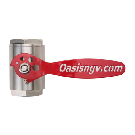
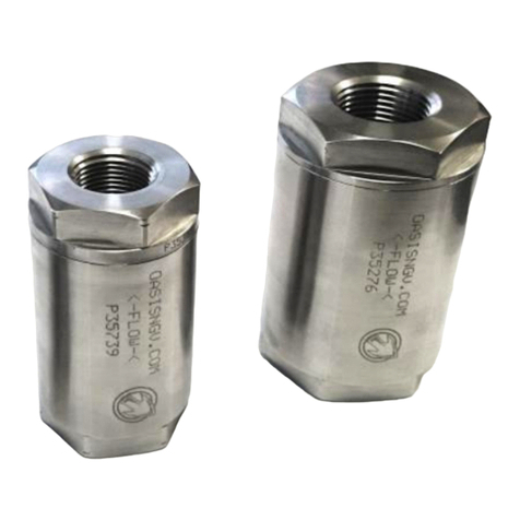
Oasis TH104 User manual

TH104
Cylinder Valves
Instruction Manual
Failure to follow these instrucons or to properly install and maintain this equipment could result in gas
leakage, re or explosion causing property damage and personal injury or death.
Oasis products must be installed, operated and maintained by trained and competent personnel in
accordance with all applicable local codes, rules and regulaons in addion to the Oasis Instrucons.
Oasis Engineering Ltd. will not be held liable in such circumstances where installaon, operaon and
maintenance procedures were performed by incompetent personnel resulng in improper assembly, unsafe
operaon, equipment damage or personal injury.
The Oasis 100 series Cylinder Head Valve models TH104 have been designed and manufactured in accord-
ance with sound engineering pracce (SEP) and comply with the SEP requirements of the EU Pressure Equip-
ment Direcve 2014/68/EU. Technical documents required by the Direcve are held by the Manufacturer.
Instruction Manual
Oasis Engineering Ltd
129 Birch Avenue, Tauranga, New Zealand.
T: +64 7 928 3808
E: info@oasisNGV.com
W: www.OasisNGV.com

2
We reserve the right to modify product specifications without prior notice. TH104-INS-01 1723 © Oasis Engineering Limited
Safety
Tools Required
Ensure the system is clean of debris,
vented and isolated before any
installation or servicing work is carried
out.
Warning!
High pressure gas and gas equipment can cause serious harm to
both infrastructure and personnel if safety precautions are not
followed.
Oasis recommends considering the use of the following PPE when
working with high pressure along with any other site specific health
and safety requirements:
Torque Wrench
(With 1/4” Hex)
Anti Seize Grease
- Swagelok Silver Goop
- Omega 99
- or similar
Spray bottle
(Snoop or
soapy water)
Yellow, Gas Rated, PTFE Thread Tape
- AW TITASEAL
- McMaster-Carr High-Density Thread
Sealant Tape
- Blue-Monster gas-guard
- Or Similar
Anaerobic Thread Sealant
with PTFE (Optional)
- Loctite 567
- Swagelok SWAK
- Hernon Dripstop 940
- Gasoila FasSeal-ATS
- Or Similar
Spanner
& Crows foot
Wrench
-42mm
-26mm
Silicone Grease
-Rocol MX22
- Or similar
For all O-rings

3
We reserve the right to modify product specifications without prior notice. TH104-INS-01 1723 © Oasis Engineering Limited
Important note for use in the
European Union
The 100 series Cylinder Valve is not to be
installed in a pressure system as the sole means
of isolaon of the contents of an item of pressure
equipment from the atmosphere or from
downstream equipment which is not designed to
withstand upstream pressure.
Compliance with the UN ADRs is mandatory for
pressure systems when this device is ed to
pressure systems for transportable pressure
vessels and used for the carriage of dangerous
goods by road.
Safety
We reserve the right to modify product specifications without prior notice. TH104-INS-01 1723 © Oasis Engineering Limited

4
We reserve the right to modify product specifications without prior notice. TH104-INS-01 1723 © Oasis Engineering Limited
4. Align valve by unwinding no more than
one turn. Screw adjustable nut out until it
contacts washer.
3. Screw body fully onto adaptor by hand.
Max 1 turn
5. Tighten adjustable nut to body
and torque to spec.
Proceed to step 6 (Page 6)
1. b) UN Adaptor:
Apply silicone grease to adaptor O-ring.
Apply anti-seize grease to adaptor thread
and attach to cylinder.
42mm
crows foot
Torque to
100Nm
For non-adjustable adaptor installation, see page 5
26mm Crows foot
Recommended
Torque: 50Nm
3 to 4 turns
Please ensure that the tape covers all threads,
but does not overlap the end of the fitting
1. a) NPT Adaptor:
Apply thread tape and thread sealant.
Tighten connection hand tight before apply
two full turns with wrench.
(Optional)
If galling is a concern or unable to cover all
threads, apply a light coating over thread
tape and uncovered threads.
2. Wind nut towards the cylinder far as possi-
ble. Push back up washer and O-ring towards
the cylinder far as possible.
Proceed to step 6
When complete
(Page 6)
Installation
Instructions
Non-Adjustable Cylinder Fitting

5
We reserve the right to modify product specifications without prior notice. TH104-INS-01 1723 © Oasis Engineering Limited
3. Rotate cylinder to align valve
38mm crows foot
Torque to 70Nm
1. b) UN Adaptor:
Apply silicone grease to adaptor O-ring.
Apply anti-seize grease to adaptor thread
and attach to cylinder.
42mm
crows foot
Torque to
100Nm
3 to 4 turns
Please ensure that the tape covers all threads,
but does not overlap the end of the fitting
1. a) NPT Adaptor:
Apply thread tape and thread sealant.
Tighten connection hand tight before apply
two full turns with wrench.
(Optional)
If galling is a concern or unable to cover all
threads, apply a light coating over thread
tape and uncovered threads.
2. Apply anti-seize to threads and screw
body fully onto adaptor. Torque to spec.
Proceed to step 6
When complete
(Page 6)
We reserve the right to modify product specifications without prior notice. TH104-INS-01 1723 © Oasis Engineering Limited
Installation
Instructions
Non-Adjustable Cylinder Fitting

6
We reserve the right to modify product specifications without prior notice. TH104-INS-01 1723 © Oasis Engineering Limited
7. a) Tighten end connection to PRD system.
Note: If using PRD adaptor, refer to 7. b).
6. Attach fitting to end cap.
8. If valve has a top port, insert blank plug
into port and tighten to fitting suppliers
recommendations.
9. Installation complete, leak test on first use
with snoop or soapy water.
1/4” Hex head
7. b) Install PRD to adaptor and torque to manufacturers spec.
Installation
Instructions
For VTI PRD K905-613.0
a. Ensure burst disc is in place before installing PRD.
b. Carefully remove plastic cap.
c. Install PRD into Oasis adaptor.
d. Torque PRD to 18+3 Nm. Use 6mm Hex head.
e. Replace plastic cap on PRD.
f. Install adaptor with o-ring into valve. Torque to 30Nm.

7
We reserve the right to modify product specifications without prior notice. TH104-INS-01 1723 © Oasis Engineering Limited
Using
Commissioning Port
3. Remove commissioning plug from valve.
For valves that have a commissioning port on the top face, a special plug (part # XTH104-73,
sold separately) can be used to seal off the cylinder when commissioning to save time and
removes the need to fill the cylinder.
1. Screw commissioning plug into valve port.
Make sure O-rings are clean and not damaged
before installing.
1/4” Hex head
Recommended
Torque: 30Nm
Internal leaking will come through the vent hole in the
center of the commissioning plug.
4. Insert blank plug into port and tighten to
fitting suppliers recommendations and leak test.
2. Leak test system before commissioning.
Make sure all valves are open.
Ensure pressure is vented from system when
complete.
DO NOT LEAVE
COMMISSIONING PLUG IN
VALVE, THE CYLINDER WILL
NOT BE ABLE TO BE FILLED.
We reserve the right to modify product specifications without prior notice. TH104-INS-01 1723 © Oasis Engineering Limited

8
We reserve the right to modify product specifications without prior notice. TH104-INS-01 1723 © Oasis Engineering Limited
Important: Actuate valve 4 times before use to ensure initial sealing.
1. Open 2. Closed
Operation
Instructions

9
We reserve the right to modify product specifications without prior notice. TH104-INS-01 1723 © Oasis Engineering Limited
Servicing
Tools Required
Cleaner
(Warm Soapy
Water or Similar)
Pick Tool
Spanner
(Wrenches)
-42mm
-34mm
-26mm
-13mm
Anti Seize Grease
(Loctite 771 or
Similar)
For All Threads
Sockets
-34mm
-13mm
Torque Wrench
The Complete Oasis Seal Kit must be used
Service Kit Parts
1 x Large Adaptor O-ring**1 x Small Adaptor O-ring
(908 Nitrile 90) (216 Nitrile 90)
2 x Seats 1 x Stem 1 x Ball*
1 x Gland 2 x Seat O-rings1 x Silicone grease
(1x 906 Nitrile 90)
(2x 908 Nitrile 90)
3 x SAE Port O-rings*** 1 x Cap O-ring
*It is normal for the service kit to include a ball with a small hole in the bottom
**Large adaptor O-ring is only used for UN threaded cylinders
***The spare 908 O-ring is only used for TH104 Valves with a commissioning port.
Pliers
Pick Tool
Part # TOOL-PICK
(Sold separately)
Oasis Plastic Tool
Part Number:
TOOL-BVASSY
(Sold separately)
or Similar
We reserve the right to modify product specifications without prior notice. TH104-INS-01 1723 © Oasis Engineering Limited

10
We reserve the right to modify product specifications without prior notice. TH104-INS-01 1723 © Oasis Engineering Limited
1. Vent pressure from system
and remove valve. 2. Remove adaptor.
3. Discard adaptor O-rings.
Open and close valve to ensure all trapped gas is released
4. Remove handle.
13mm Spanner needed.
Servicing
Assembly

11
We reserve the right to modify product specifications without prior notice. TH104-INS-01 1723 © Oasis Engineering Limited
8. Discard the ball.
6. Remove end cap.
34mm Spanner needed.
7. Discard the seat and the
O-ring in the cap.
5. Discard gland.
We reserve the right to modify product specifications without prior notice. TH104-INS-01 1723 © Oasis Engineering Limited
Servicing
Assembly

12
We reserve the right to modify product specifications without prior notice. TH104-INS-01 1723 © Oasis Engineering Limited
10. Discard the seat and O-ring.
11. Discard the cap O-ring.
Do not scratch body
12. Clean the components and inspect for damage.
Check for excessive
damage to sealing faces
and threads
9. Discard the stem.
Push Stem firmly down into body.
Servicing
Disassembly

13
We reserve the right to modify product specifications without prior notice. TH104-INS-01 1723 © Oasis Engineering Limited
5. Fit cap O-rings. 6. Tighten end cap.
4. Insert 2nd seat.
Click
34mm Socket
Recommended
End Cap Torque: 60Nm
2. Insert stem assembly.
3. Insert ball.
1. Insert 1st seat and O-ring.
We reserve the right to modify product specifications without prior notice. TH104-INS-01 1723 © Oasis Engineering Limited
Servicing
Assembly

14
We reserve the right to modify product specifications without prior notice. TH104-INS-01 1723 © Oasis Engineering Limited
8. Assemble handle components.
13mm Socket
Recommended
Handle Nut Torque: 3Nm
9. Tighten handle nut.
10. Insert O-rings.
908 Nitrile 90
216 Nitrile 90
(UN cylinder fitting only)
7. Insert gland.
Servicing
Assembly

15
We reserve the right to modify product specifications without prior notice. TH104-INS-01 1723 © Oasis Engineering Limited
Fit small SAE port O-ring
(906 Nitrile 90)
11a. Follow installation instructions on page 3 of this manual for re-fitment of valve. Replace SAE
port O-rings with those supplied in service kit. Use TH104-SK2 and discard extra 908 O-Ring.
Fit medium SAE port O-ring
(908 Nitrile 90)
Apply silicone grease to all O-rings and anti
seize to all threads
11b. Follow installation instructions on page 3 of this manual for re-fitment of valve. Replace SAE
port O-rings with those supplied in service kit TH104-SK2 and discard extra 906 O-Ring.
Apply silicone grease to all O-rings and anti
seize to all threads
Fit small SAE port O-ring
(906 Nitrile 90)
Fit medium SAE port O-ring
(908 Nitrile 90)
Fit medium SAE port O-ring
(908 Nitrile 90)
We reserve the right to modify product specifications without prior notice. TH104-INS-01 1723 © Oasis Engineering Limited
Servicing
Assembly
Table of contents
Other Oasis Control Unit manuals
Popular Control Unit manuals by other brands

Ai-Thinker Technology
Ai-Thinker Technology Ra-01SC manual

Parker
Parker Series DFplus Operation manual

United Technologies
United Technologies Kidde FX-NAC Installation sheet

Bosch
Bosch rexroth M1-16 Series instruction manual

Danfoss
Danfoss REG-SA SS 15 installation guide

Wieland
Wieland PROFIBUS-DP Series Translation of the original instructions