DE
UDHOME 2 G (Artikel-Nr. 7368324, 7368330, 7368326,
7368332, 7368340, 7368346, 7368342, 7368348)
Produktbeschreibung
Quadratische Bodensteckdose für den Einbau in Estrich-
und Systemböden in trockenen Räumen, mit trocken ge-
pflegten Fußböden. Gehäuse mit einem Leitungsauslass
im Klappdeckel.
1Klappdeckel (2 Varianten: mit und ohne Bodenbe-
lagsaussparung)
2Gehäuse
3Nivellierschrauben
4Leerrohreinführung
5Montageträger Starkstrom (Bestückung je nach
Lieferumfang)
6Schnurauslass
7Montageschutzdeckel
Bodensteckdose montieren
Hinweis:
Die Bodensteckdose kann maximal auf eine Höhe
von 135 mm (vom Betonboden bis zur Oberkante
Fertigfußboden) nivelliert werden. Wenn eine größe-
re Höhe erforderlich ist, muss die Höhenerweiterung
verwendet werden.
Montageträger entfernen:
1. Klappdeckel 1entnehmen.
2. Befestigungsschrauben leicht lösen und Montage-
träger Starkstrom 5entfernen.
3. Bohrlöcher auf Betonboden anzeichnen und boh-
ren.
Leerrohreinführungen
4aushebeln:
Nach Bedarf die vorgeprägten Leerrohreinführungen
4mit einem geeigneten Werkzeug (z. B. Schlitz-
schraubendreher) aushebeln.
Bodensteckdose montieren:
Gehäuse 2mit einem geeignetem Befestigungsma-
terial (z. B. Dübel und Schrauben) auf dem Betonbo-
den montieren.
5
Bodensteckdose nivellieren:
Gehäuse 2auf die geplante Oberkante des Estrichs
nivellieren. Dabei die Mindesteinbautiefe je nach De-
ckelvariante nicht unterschreiten. (Hmin1: Deckel mit
Dekorplatte: 100 mm; Hmin2: Deckel mit Bodenbe-
lagsaussparung: 110 mm)
Installationsrohre fixieren:
Installationsrohre max. 2 mm in die Bodensteckdose
einführen und außerhalb am Boden fixieren.
Estrich verlegen
ACHTUNG
Beschädigungsgefahr durch Estrich!
Das Eindringen des Estrichs in die Bodensteckdose
führt zu Produktschäden!
Bodensteckdose vor der Estrichverlegung mit dem
Montagedeckel schützen.
Hinweis:
Vor den Estricharbeiten eine geeignete Trennlage
am Gehäuse der Bodensteckdose anbringen, um
die Schallübertragung zu reduzieren und eine
Estrichanhaftung am Gehäuse zu vermeiden.
Montageschutzdeckel aufsetzen:
1. Klappdeckel 1schließen.
2. Montageschutzdeckel 7aufsetzen.
3. Trennlage am Gehäuse 2anbringen.
Hinweis:
Bei dem Klappdeckel mit Bodenbelagsaussparung
das Trittschutzblech zwischen Montageschutzde-
ckel und Bodensteckdose legen.
Estrich verlegen:
Estrich bündig mit der Oberkante des Montage-
schutzdeckels 7verlegen und an die Bodensteck-
dose anarbeiten.
Bodenbelag aufbringen und nivellieren
ACHTUNG
Beschädigungsgefahr durch Fugenmörtel!
Der Kontakt der Bodensteckdose mit Fugenmörtel
führt zu Produktschäden!
Bei der Anbringung von Fugenmörtel in der
Dehnungsfuge entlang der Bodensteckdose,
müssen Rahmen und Deckel vor dem Fugenmateri-
al geschützt werden.
ACHTUNG
Beschädigungsgefahr durch Fugenmaterial/
Kleber!
Das Eindringen des Fugenmaterials/Klebers in die
Bodensteckdose führt zu Produktschäden!
Innenraum nach den Bodenbelagsarbeiten
gründlich reinigen.
Montageschutzdeckel entfernen:
1. Montageschutzdeckel 7mit Teppichmesser auf-
schneiden.
2. Klappdeckel 1öffnen.
Bodenbelag aufbringen und Bodensteckdose nivel-
lieren:
ACHTUNG
Beschädigungsgefahr!
Ein zu hohes Nivellieren der Bodensteckdose führt
zu Produktschäden!
Die Bodensteckdose nur bis zur maximalen
Nivellierhöhe (H max) nivellieren. Es gilt: max. 135
mm (Estrich + Bodenbelag).
1. Bodenbelag aufbringen, dabei die Breite der Deh-
nungsfuge in Abhängigkeit des Bodenbelags und
des dauerelastischen Fugenmaterials auswählen.
2. Bodensteckdose auf die Oberkante des Bodenbe-
lags nivellieren.
Stopfen einsetzen:
ACHTUNG
Beschädigungsgefahr durch fehlende Stopfen!
Durch fehlende Stopfen können Feuchtigkeit und
Verunreinigungen in die Nivellierhülsen dringen,
was zu Produktschäden führt!
Stopfen in die 4 Nivellierhülsen einsetzen.
Die beiliegenden Stopfen in die Gewindehülsen ein-
setzen.
Dehnungsfuge verfüllen:
ACHTUNG
Beschädigungsgefahr durch unzureichende
Dehnungsfuge!
Sich ausdehnender Bodenbelag ohne ausreichende
Dehnungsfuge führt zu Produktschäden!
Bodenbelag am Gehäuse der Bodensteckdose
spannungsfrei anarbeiten. Dazu ausreichende
Dehnungsfuge mit dauerelastischem Fugenmaterial
verfüllen.
Dehnungsfuge rund um die Bodensteckdose mit ei-
nem geeigneten flexiblen, dauerelastischen Material
(z. B. Silikon) verfüllen.
Hinweis:
Bei dem Klappdeckel mit Bodenbelagsaussparung
die Dehnungsfuge im Deckel (ca. 3-5 mm) mit
einem geeigneten flexiblen, dauerelastischen
Material (z. B. Silikon) verfüllen.
ACHTUNG
Beschädigungsgefahr durch ätzende Reini-
gungsmittel!
Der Kontakt mit säure-/chloridhaltigen Reinigungs-
mitteln (z. B. Zementschleierentferner) führt zu
Produktschäden!
Sollte die Grundreinigung des Bodens mit diesen
Reinigungsmitteln durchgeführt werden, empfehlen
wir den Deckel während der Reinigung zu
entnehmen. Dabei ist sicherzustellen, dass keine
Feuchtigkeit in Rahmen und Gehäuse eindringt.
Sollte der Deckel während der Reinigung im
Rahmen verbleiben, sind alle Bauteile inkl.
Innenraum gegenüber den ätzenden Reinigungs-
mitteln (z. B. durch flächiges Abkleben) zu
schützen. Sollten die Bauteile in Kontakt mit
ätzenden Reinigungsmitteln kommen, sind diese
sowie die Dichtungen mit klarem Wasser zu
reinigen.
Elektroinstallation vornehmen
Anschlussleitung einführen:
Anschlussleitung der Steckdose 5einführen und
den Außenmantel bis zur Kabeleinführung abisolie-
ren.
ACHTUNG
Beschädigungsgefahr durch unsachgemäße
Montage!
Unsachgemäße Montage führt zu Produktschäden!
Kabel so weit wie möglich abisolieren, um den
korrekten Einbau der Steckdosen zu gewährleisten.
Steckdose anschließen:
Steckdose 5mit der Anschlussleitung anschließen.
Potentialausgleich herstellen:
Bodensteckdose in Schutzpotentialausgleich einbe-
ziehen.
Montageträger festschrauben:
Hinweis:
Die Kabel zu einer Schlaufe legen, damit die Monta-
ge des Montageträgers einfacher wird.
1. Montageträger bis zum Anschlag ins Gehäuse
schieben und anschließend die Befestigungsschrau-
ben anziehen.
Hinweis:
Der Klappdeckel kann in alle Richtungen geöffnet/
geschlossen werden.
2. Klappdeckel 1schließen.
Bodensteckdose entsorgen
– Verpackung wie Hausmüll
– Bodensteckdose wie Metallschrott
– Örtliche Müllentsorgungsvorschriften beachten
Technische Daten
UDHOME 2 G
Dimensionen 140 x 140 x 100 mm
Nivellierbereich je nach Deckelvariante
+ 25 mm/+ 35 mm
Mindesteinbautiefe je nach Deckelvariante
mit Dekorplatte 100 mm
mit Bodenbelag 110 mm
Bodenpflegeart
nach EN 50085-2-2 trocken
Werkstoff Edelstahl
Inserting the plugs:
ATTENTION
Risk of damage through missing plugs!
Missing plugs can allow moisture and impurities to
enter the height-adjustment sleeves, leading to
product damage!
Insert the plugs into the 4 height adjustment
sleeves.
Insert the supplied plugs into the threaded sleeves.
Filling the expansion joint:
ATTENTION
Risk of damage through insufficient expansion
joint!
An expanding floor covering without a sufficient
expansion joint leads to product damage!
Work the floor covering up to the floor socket
housing with no tension. To achieve this, fill a
sufficient expansion joint with permanently elastic
joint material.
Fill the expansion joint around the floor socket with a
suitable flexible, permanently elastic material (e.g.
silicone).
Note:
With the hinged cover with floor covering recess, fill
the expansion joint (approx. 3–5 mm) with a suitable
flexible, permanently elastic material (e.g. silicone).
ATTENTION
Risk of damage from caustic cleaning agents!
Contact with cleaning agents containing acids/
chlorides (e.g. cement residue removers) will cause
damage to the product!
Should the basic cleaning of the floor be carried out
with these cleaning agents, we recommend that the
cover should be removed during cleaning. Ensure
that no moisture can ingress into the frame and
housing.
Should the cover remain in the frame during
cleaning, then all the components, including the
interior, should be protected against the caustic
cleaning agents (e.g. by widespread masking).
Should the components come into contact with
caustic cleaning agents, then they and the seals
should be cleaned with clear water.
Performing the electrical installation
Inserting the connection cable:
Insert the connection cable of the socket 5and strip
the outer jacket up to the cable entry.
ATTENTION
Risk of damage through incorrect mounting!
Improper mounting can lead to product damage!
Strip the cables as far as possible, in order to
guarantee the correct installation of the sockets.
Connect the socket:
Connect the socket 5to the connection cable.
Creating equipotential bonding:
Include the floor socket in the protective equipotenti-
al bonding.
Screwing the mounting support tight:
Note:
Make the cable into a loop to simplify the mounting
of the mounting support.
1. Push the mounting support into the housing and
then tighten the fastening screws.
Note:
The hinged cover can be opened/closed in all
directions.
2. Close the hinged cover 1.
Disposing of the floor socket
– Packaging as household waste
– Floor socket with scrap metal
– Comply with the local waste disposal regulations
Technical data
UDHOME 2 G
Dimensions 140 x 140 x 100 mm
Height adjustment
range Depending on the cover
variant
+ 25 mm/+ 35 mm
Minimum installation
depth
Depending on the cover
variant
With decor plate 100 mm
With floor covering recess 110 mm
Floor care type
according to EN
50085-2-2
Dry
Material Stainless steel
ES
UDHOME 2 G (n.° de artículo 7368324, 7368330,
7368326, 7368332, 7368340, 7368346, 7368342,
7368348)
Descripción del producto
Unidad completa cuadrada para el montaje en suelos
modulares y pavimentos en espacios secos con suelos
EN
UDHOME 2 G (Article No. 7368324, 7368330, 7368326,
7368332, 7368340, 7368346, 7368342, 7368348)
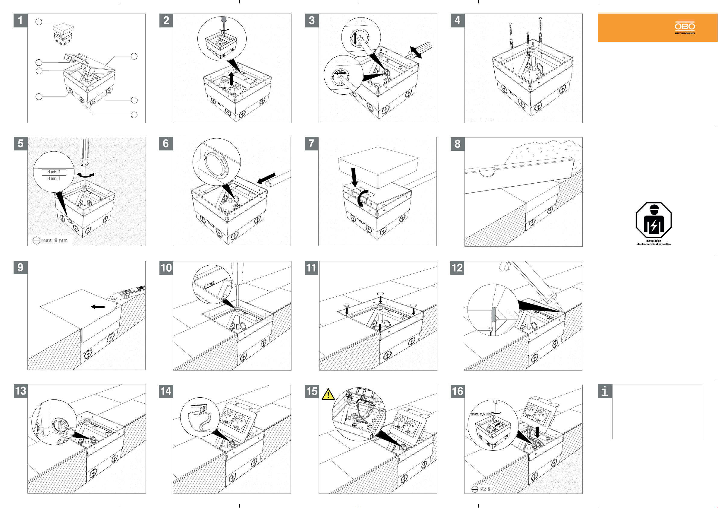
Product description
Square floor socket for installation in screed and system
floors in dry rooms, with dry-care floors. Housing with a
cable outlet in the hinged cover.
1Hinged cover (2 variants: With and without floor
covering recess)
2Housing
3Height-adjustment screws
4Empty pipe entry
5Heavy current mounting support (equipment ac-
cording to scope of delivery)
6Cord outlet
7Mounting protection cover
Mounting the floor socket
Note:
The floor socket can be adjusted to a maximum
height of 135 mm (from the concrete floor to the top
edge of the finished floor). If a greater height is
required, then the height extension must be used.
Removing the mounting support:
1. Remove the hinged cover 1.
2. Slacken the fastening screws slightly and remove
the heavy current mounting support 5.
3. Draw the drill holes on the concrete floor and drill
them.
Lever out the empty pipe entries 4:
If required, lever out the pre-marked empty pipe
entries 4with a suitable tool (e.g. slotted screwdri-
ver).
Mounting the floor socket:
Mount the housing 2with suitable fastening materi-
al (e.g. anchors and bolts) on the concrete floor.
5
Adjusting the height of the floor socket:
Adjust the height of the housing 2to the planned
top edge of the screed. Depending on the cover vari-
ant, the minimum installation depth must not be un-
dercut. (Hmin1: cover with decor plate: 100 mm;
Hmin2: cover with floor covering recess: 110 mm)
Fixing the installation pipes:
Insert the installation pipe max. 2 mm into the floor
socket and fix it outside on the floor.
Laying the screed
ATTENTION
Risk of damage from screed!
The ingress of screed into the floor socket can lead
to product damage!
Before screed laying, protect the floor socket with
the mounting cover.
Note:
Before screed work, apply a separating layer to the
housing of the floor socket, in order to reduce noise
transmission.
Attaching the mounting protection cover:
1. Close the hinged cover 1.
2. Attach the mounting protection cover 7.
3. Apply the separation layer to the housing 2.
Note:
When using the hinged cover with a floor covering
recess, lay the footfall protection plate between the
mounting protection cover and floor socket.
Laying the screed:
Lay the screed flush to the top edge of the mounting
protection cover 7and work it up to the floor socket.
Applying the floor covering and adjusting the
height
ATTENTION
Risk of damage through joint mortar!
Contact between the floor socket and joint mortar
leads to product damage!
When applying joint mortar to the expansion joint
along the floor socket, the frame and cover must be
protected against the joint material.
ATTENTION
Risk of damage from joint material/adhesive!
The ingress of the joint material/adhesive into the
floor socket can lead to product damage!
Thoroughly clean the interior after floor covering
work.
Removing the protective mounting cover:
1. Cut open the mounting protection cover 7with a
carpet knife.
2. Open the hinged cover 1.
Applying the floor covering and adjusting the height
of the floor socket:
ATTENTION
Risk of damage!
Adjustment of the floor socket to an excessive
height can lead to product damage!
Only adjust the height of the floor socket to the
maximum adjustment height (H max). Ensure a
maximum of 135 mm (screed + floor covering).
1. Apply the floor covering, selecting the width of the
expansion joint according to the floor covering and
the permanently elastic joint material.
2. Adjust the height of the floor socket to the upper
edge of the floor covering.
que requieren una limpieza en seco. Carcasa con una
salida de cable en la tapa abatible.
1Tapa abatible (2 variantes: con y sin entalladura
para revestimiento de suelo)
2Carcasa
3Tornillos de nivelación
4Entrada para tubo vacío
5Soporte de montaje corriente de alimentación
(equipado según el volumen de suministro)
6Salida de cable
7Tapa protectora de montaje
Montaje de la toma de suelo
Nota:
La toma de suelo puede nivelarse a una altura
máxima de 135 mm (desde el suelo de hormigón
hasta el borde superior del suelo). Si es necesaria
más altura, debe utilizarse la ampliación de altura.
Retirada del soporte de montaje:
1. Retire la tapa abatible 1.
2. Afloje ligeramente los tornillos de fijación y retire el
soporte de montaje de corriente de alimentación 5.
3. Marque los taladros que va a realizar en el suelo
de hormigón y perfórelos.
Extracción ejerciendo palanca en las entradas para
tubos vacíos 4:
Si es necesario, abra las entradas pretroqueladas
para tubos vacíos 4utilizando una herramienta
adecuada (p. ej., destornillador plano).
Montaje de la toma de suelo:
Monte la carcasa 2con un material de fijación ade-
cuado (p. ej., tacos y tornillos) sobre el suelo de hor-
migón.
5
Nivelación de la toma de suelo:
Nivele la carcasa 2con el borde superior del pavi-
mento. Dependiendo del tipo de tapa, la profundidad
mínima de instalación no debe ser reducida. (Hmin1:
cubierta con placa decorativa: 100 mm; Hmin2: cu-
bierta con hueco para revestimiento de piso: 110
mm)
Fijación de los tubos de instalación:
Introduzca los tubos de instalación como máx. 2 mm
en la toma de suelo y fíjelos por fuera al suelo.
Aplicación del mortero
ATENCIÓN
¡Peligro de daños por el mortero!
¡La entrada de mortero en la toma de suelo provoca
daños en el producto!
Antes de colocar el mortero, proteja la toma de
suelo con la tapa de montaje.
Nota:
Antes de los trabajos con mortero, coloque una
capa de separación en la carcasa de la toma de
suelo para reducir la transmisión acústica.
Colocación de la tapa protectora de montaje:
1. Cierre la tapa abatible 1.
2. Coloque la tapa protectora de montaje 7.
3. Coloque una capa de separación en la carcasa
2
.
Nota:
En la tapa abatible con entalladura para revesti-
miento de suelo. coloque la chapa antideslizante
entre la tapa de protección de montaje y la toma de
suelo.
Aplicación del mortero:
Aplique mortero de manera que quede nivelado con
el borde superior de la cubierta de protección de
montaje 7y en contacto directo con la toma de sue-
lo.
Colocación y nivelación del pavimento
ATENCIÓN
¡Peligro de daños por mortero de junta!
¡La toma de suelo resulta dañada si entra en
contacto con el mortero de junta!
Al aplicar mortero en la junta de expansión a lo
largo de la toma de suelo, debe protegerse el
marco y la tapa para evitar que entre en contacto
con el pegamento.
ATENCIÓN
¡Peligro de lesiones por material de adhesión /
pegamento!
¡La entrada de pegamento o tapajuntas en la toma
de suelo provoca daños en el producto!
Limpie en profundidad el compartimento interior
cuando finalice los trabajos de revestimiento del
suelo.
Retirada de la tapa protectora de montaje:
1. Corte la tapa protectora de montaje 7con un
cúter.
2. Abra la tapa abatible 1.
Colocación del revestimiento de suelo y nivelación
de la toma de suelo:
ATENCIÓN
¡Peligro de dañar componentes!
¡Una nivelación demasiado elevada de la toma de
suelo causa daños en el producto!
Nivele la toma de suelo solamente hasta la altura
de nivelación máxima (Al máx). Es válido: máx. 135
mm (pavimento + revestimiento de suelo).
1. Aplique el revestimiento del suelo, seleccionando
la fuga de expansión en función del revestimiento y
del material de fuga de elasticidad permanente.
2. Nivele la toma de suelo con el borde superior del
revestimiento del suelo.
Colocación de los tapones:
ATENCIÓN
¡Peligro de daños por falta de tapones!
¡Si faltan tapones puede entrar humedad y
suciedades en los manguitos de nivelación, lo que
provoca daños en el producto!
Coloque tapones en los 4 manguitos de nivelación.
Introduzca los tapones adjuntos en los manguitos
roscados.
Relleno de la junta de expansión:
ATENCIÓN
¡Riesgo de daños por junta de expansión
insuficiente!
¡La expansión del revestimiento del suelo sin una
junta de expansión suficiente provoca daños en el
producto!
Fije el revestimiento de suelo a la carcasa de la toma
de suelo sin tensiones. Para ello, rellene la junta de
expansión insuficiente con material de junta de
elasticidad permanente.
Rellene la junta de expansión alrededor de la toma de
suelo con un material flexible adecuado de elastici-
dad permanente (p. ej., silicona).
Nota:
En la tapa abatible con entalladura para revestimien-
to de suelo rellene la junta de expansión en la tapa
(aprox. 3-5 mm) con un material flexible adecuado
de elasticidad permanente (p. ej., silicona).
ATENCIÓN
¡Riesgo de daños por agentes de limpieza
corrosivos!
¡El contacto con agentes de limpieza ácidos / con
cloro (limpiadores de cemento) provoca daños en el
producto!
En caso de limpiar el suelo con este agente de
limpieza, le recomendamos retirar la tapa durante la
limpieza. Asegúrese de que no entre humedad en el
marco ni en la carcasa.
Si la tapa debe permanecer en el marco durante la
limpieza, proteja todos los componentes, incluido el
compartimento interior, de productos de limpieza
corrosivos (p. ej. protegiéndolos con cinta adhesiva).
En caso de que los componentes entren en contacto
con productos de limpieza corrosivos, limpie éstos y
las juntas con agua clara.
Instalación eléctrica
Introducción de la línea de conexión:
Introduzca la línea de conexión del enchufe hembra
5y pélela hasta la entrada de cables.
ATENCIÓN
¡Peligro de daños por montaje incorrecto!
¡Un montaje incorrecto puede ocasionar daños en el
producto!
Pele el cable todo lo posible para garantizar el
montaje correcto de los enchufes hembra.
Conexión del enchufe hembra:
Conecte el enchufe hembra 5con la línea de conexión.
Establecimiento de la conexión equipotencial:
Integre la toma de suelo en la conexión equipotencial de
protección.
Atornillamiento del soporte de montaje:
Nota:
Haga un lazo con el cable para que el montaje del
soporte de montaje sea más sencillo.
1. Deslice el soporte de montaje hasta el tope en la
carcasa y a continuación apriete los tornillos de fija-
ción.
Nota:
La tapa abatible puede abrirse/cerrarse en todas las
direcciones.
2. Cierre la tapa abatible 1.
Eliminación de la toma de suelo
– Deseche el embalaje como residuo doméstico
– La toma de suelo se desecha como chatarra
– Tenga en cuenta la normativa local de eliminación de
residuos
Datos técnicos
UDHOME 2 G
Dimensiones 140 x 140 x 100 mm
Margen de nivelación según la variante de tapa
+ 25 mm/+ 35 mm
Profundidad mínima de
montaje según la variante de tapa
Con placa decorativa 100mm
Con hueco para revestimiento 110mm
Tipo de cuidado del
suelo
según EN 50085-2-2
Seco
Material Acero inoxidable