Инструкция по установке V20-...-440
OBO BETTERMANN GmbH & Co. KG 10
RU
Описание изделия
Устройство защиты от перенапряжений для
выравнивания потенциалов в системах элек-
троснабжения согласно VDE 0100-443 (IEC
60364-4-44). Данное устройство устанавлива-
ется на монтажную шину и используется в
распределительных коробках. Разрядники от
перенапряжений (рис. 1) подключаются
отдельно и имеют кодировку на обратной сто-
роне во избежание неправильного подключе-
ния. Величина отводимого тока разрядника
составляет до 40 кА (8/20) на один полюс.
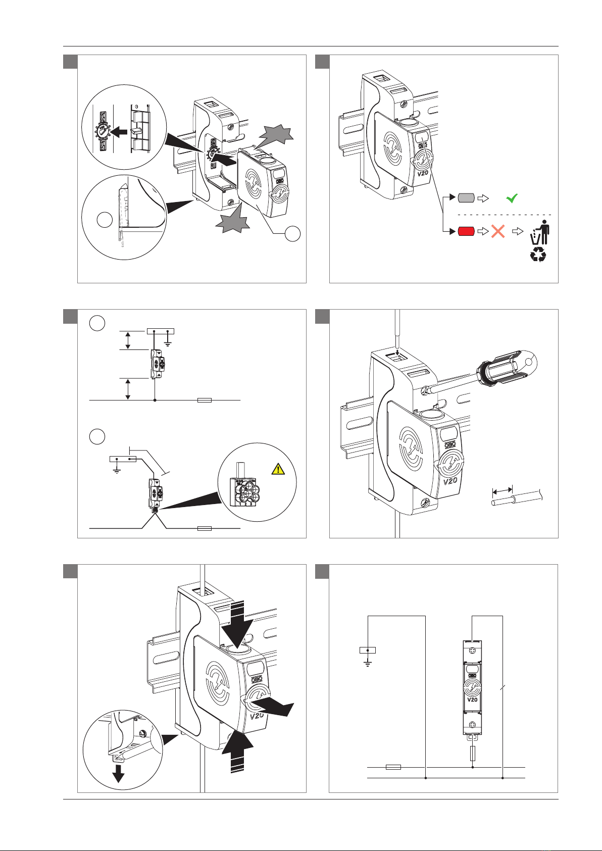
В случае неисправности оптический индика-
тор меняет свой цвет с серого на красный
(рис. ).
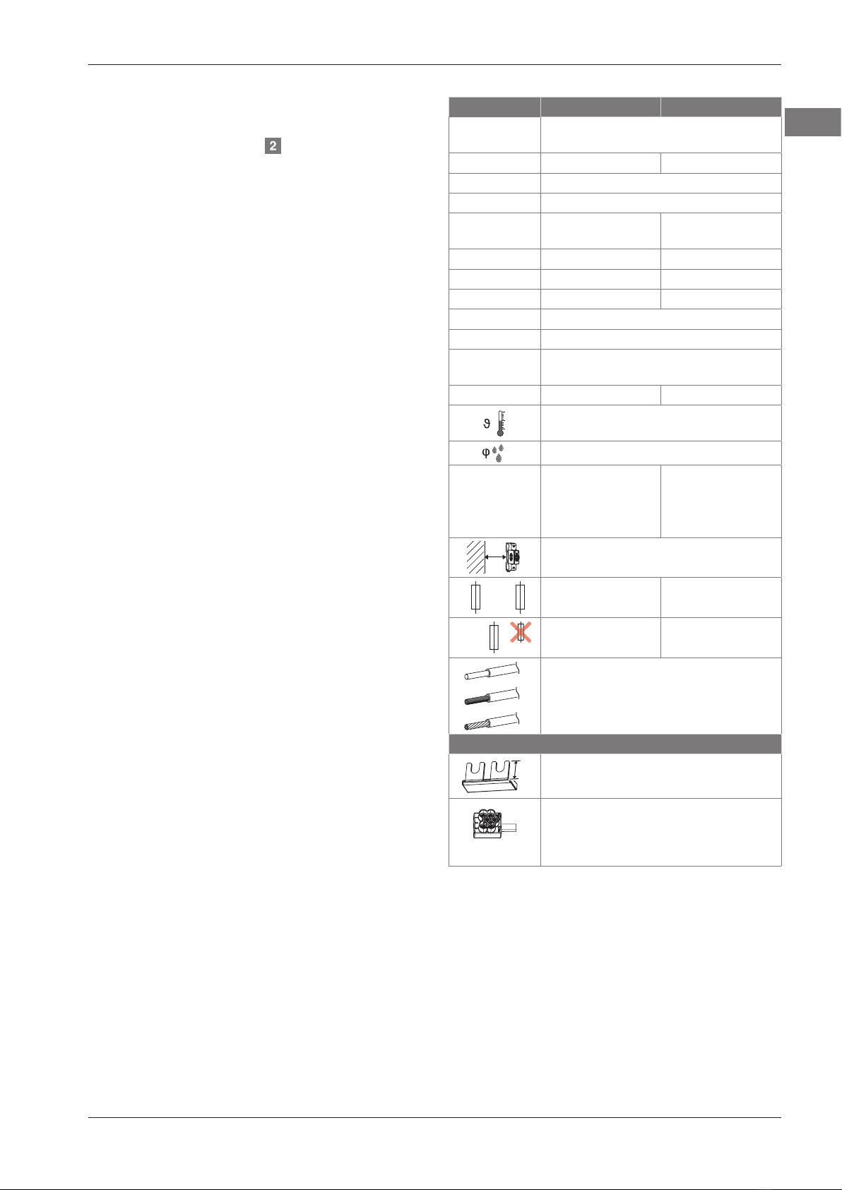
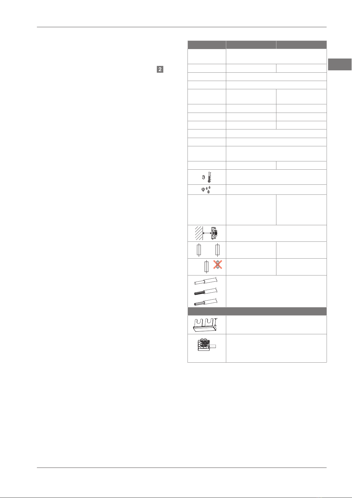
С защелкивающимся держателем монтаж-
ной шины (рис. 2).
Радиотрасса C20-0-255 выступает в качестве
разрядника от перенапряжений между нуле-
вым проводом N и защитным соединением
(заземляющий провод PE).
Целевая группа
Монтаж и подключение прибора должны вы-
полняться квалифицированным электриком.
Общие правила техники безопасности
• Перед началом работы с электропровод-
кой необходимо отключить подачу питания
и обезопасить устройство от повторного
включения!
• Запрещается проводить монтаж в грозу!
• Соблюдайте государственные законы и на-
циональные стандарты, например, VDE
0100-534 (HD 60364-5-534)!
Монтаж и установка
Монтажное положение может быть любым
(например, вертикальным или горизонталь-
ным).
Рис. : VDE 0100-534 (HD 60364-5-534) ука-
зывает на то, что
– при нарушении электропроводки 1 общая
длина подключения a + b,
– а для электропроводки V 2 длина подклю-
чения c
должна составлять преимущественно 0,5 м, и
в любом случае не должна превышать макс.
1,0 м.
Для электропроводки V применяйте соедини-
тельную клемму, № арт. 5012 010.
Внимание! Опасность перенагрузки!
Соединительная клемма 5012 010
допущена к применению для макси-
мальной нагрузки по току ≤ 50 A.
Применяйте соответствующий входной
предохранитель!
• Зафиксируйте клеммами устройство защи-
ты от перенапряжений на монтажной шине,
при этом убедитесь, что защелкивающийся
держатель монтажной шины разблокиро-
ван (рис. 2).
• Соблюдайте длину зачистки изоляции и мо-
мент затяжки (рис. ).
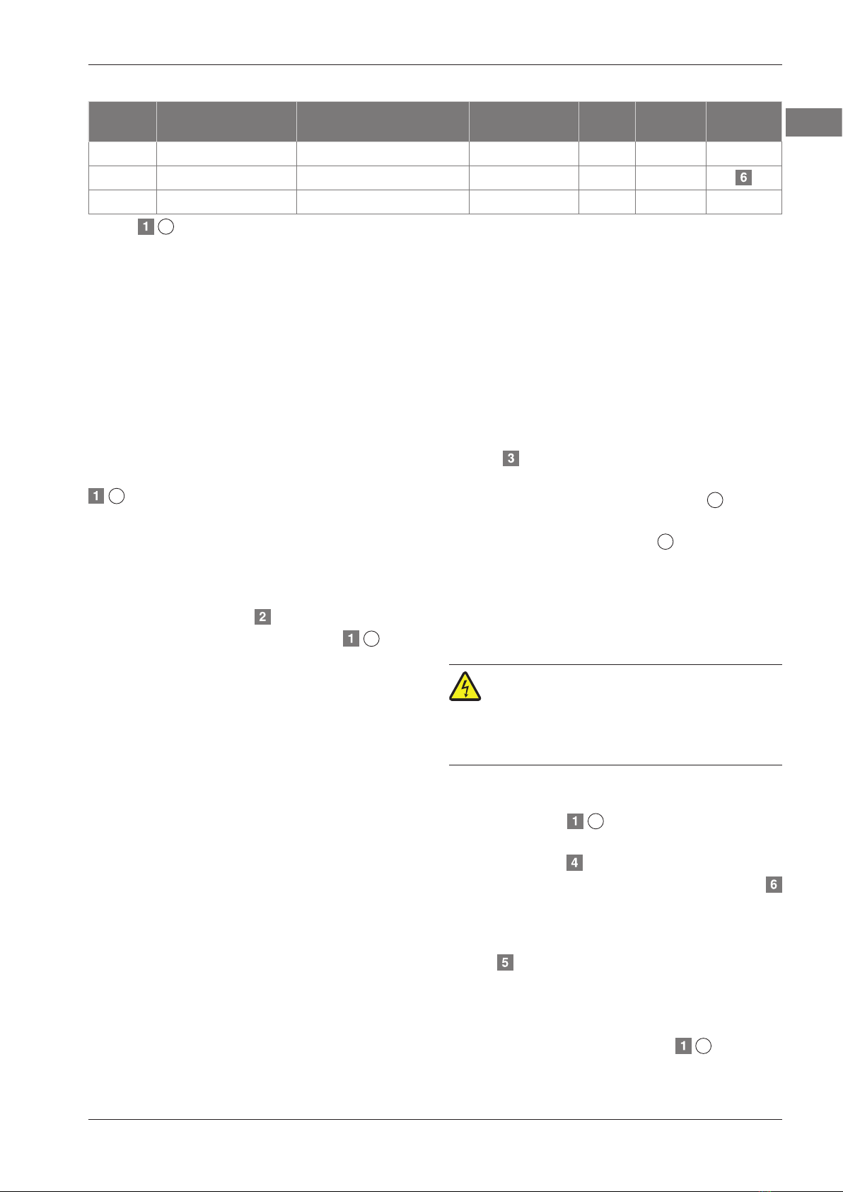
• Подключение следует производить соглас-
но электрической схеме (системы TN-C).
Демонтаж
Рис. :
• Разблокируйте и извлеките разрядник от
перенапряжений, как показано на рисунке.
• Откройте держатель монтажной шины шли-
цевой отверткой и введите в паз (см. также
рис. 2). Снимите устройство защиты от
перенапряжений.
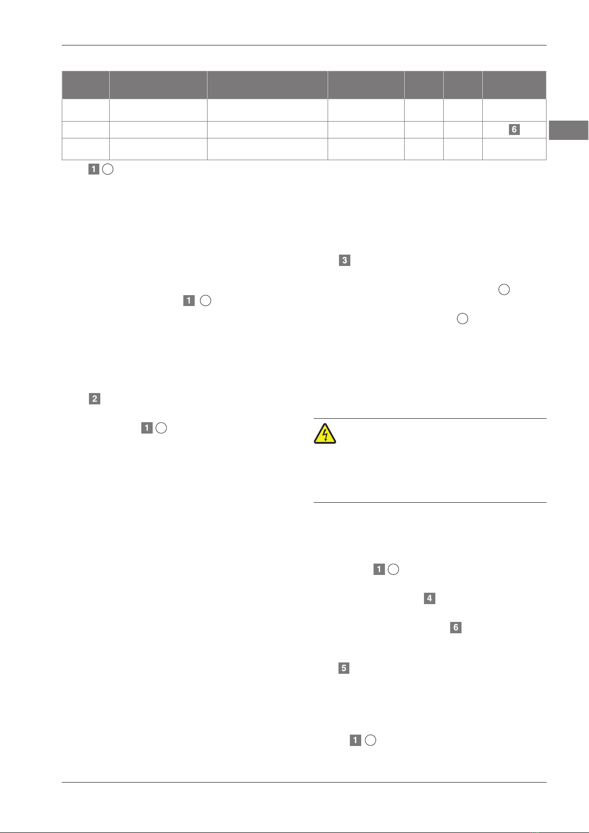
RU Surge Protective Device (Устройство защиты от перенапряжения)
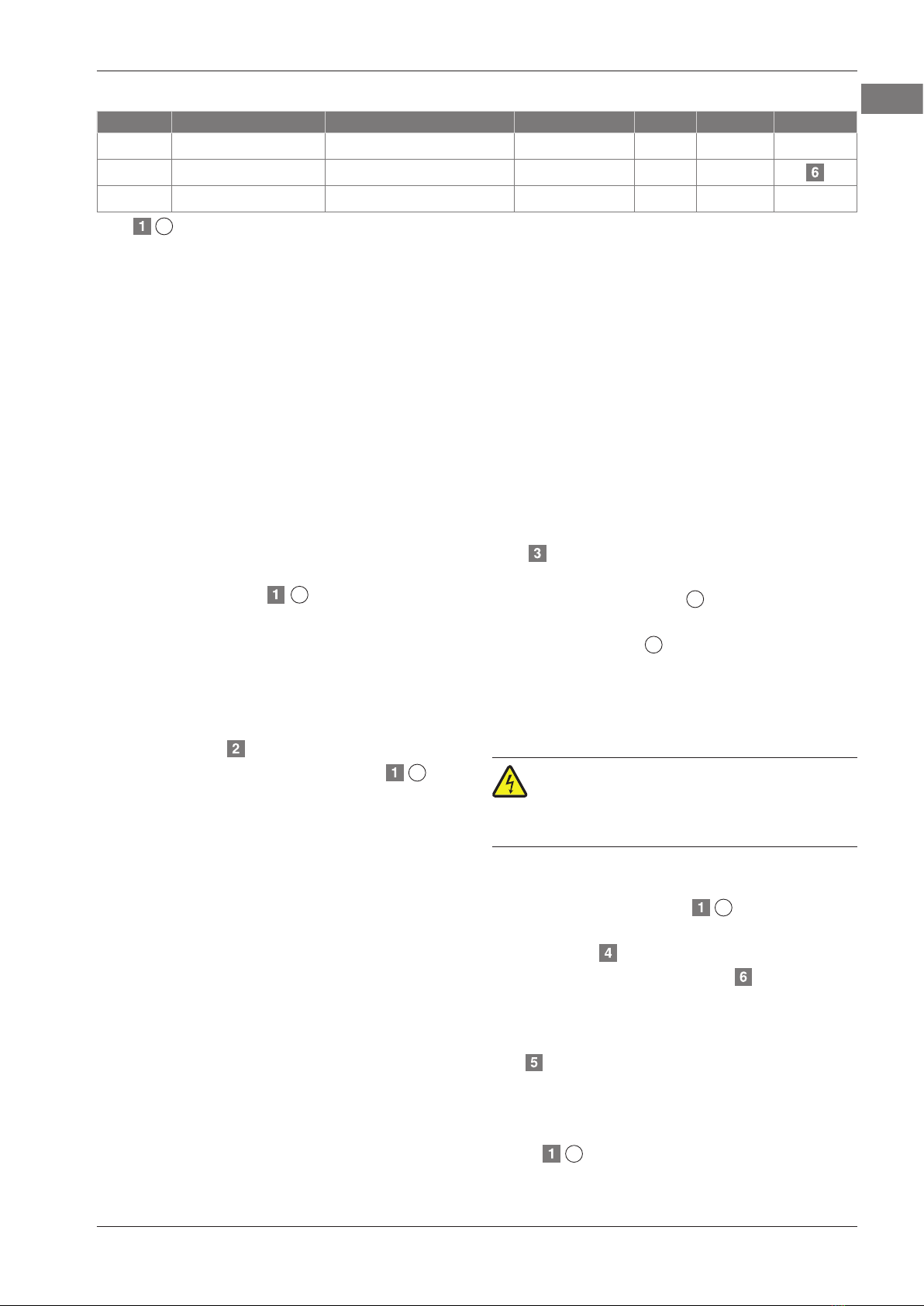
Арт. № Тип Изделие Цепь защиты ITotal IPE Электриче-
ская схема
5095 370 V20-0-440 отдельный разрядник от
перенапряжений* – – – –
5095 201 V20-1-440 однополюсный L – PE/N – –
5095 600 C20-0-255 отдельный разрядник от
перенапряжений* – – – –
*Рис. 1