OCEANAIRE 2OAC Series Manual

ENGINEERING, INSTALLATION AND SERVICE MANUAL
2OAC SERIES
Deluxe Portable Air-Cooled Spot Cooler
Form EISM-2OAC 01012019

TABLE OF CONTENTS
PAGE
GENERAL INFORMATION …................................ 1
PRODUCT DATA AND SPECIFICATIONS............ 2
UNIT DESCRIPTION
Standard Features.................................. 3
Applications / Operation.......................... 4
Electrical Configurations......................... 5
Use of Extension Cords…………………. 6
Condensate............................................ 7
Accessories………................................. 8 - 14
Inspection/Installation............................. 15
Deluxe Electronic Controller.................... 16-18
SERVICE
Replacement Parts Procedure................. 19
Troubleshooting Guide............................. 20
Preventive Maintenance........................... 21
Interior View............................................. 22
DIAGRAMS/SCHEMATICS
Piping Schematic…………………………. 23
Single Phase Wiring Diagrams................. 24 - 26
Three Phase Monitor................................ 27
Three Phase Wiring Diagrams................. 28 - 31
WARRANTY…......................................................... 32
END USER INFORMATION / TECH NOTES........... 33
FORWARD
This manual provides the user with basic details for the installation and operation of the
OceanAire 2OAC spot cooler. It is recommended to read and fully understand the
instructions outlined within this manual, before operating the 2OAC unit.
As with all commercial air conditioning equipment, it is recommended to have the 2OAC
sized and installed by a licensed specifying engineer and contractor, in accordance with
all local and state codes. The length of service received can be extended by following
the installation and preventive maintenance instructions.
NOTICE
In our ongoing process of continuous improvement, the items and procedures described
in this manual are subject to change without notice. Please note model and serial
number of the 2OAC unit when contacting the factory.

GENERAL INFORMATION
The OceanAire 2OAC is a portable air-cooled spot cooler designed for permanent or
temporary spot cooling applications. The entire unit has been built in a premium sheet
metal cabinet, equipped with heavy-duty casters for mobility. All 2OAC models come
standard with a 10-foot power cord for electrical connection and added mobility in
service. These units direct cool air to specific areas or objects through a discharge grille
located on the upper-front of the unit, while rejecting heat from the top of the unit. The
2OAC models range in capacities from 12,000 BTU/HR to 60,000 BTU/HR to satisfy
most space cooling requirements.
The 2OAC is a self-contained unit with the entire system (evaporator and condenser
blower assemblies, electrical and refrigeration components), neatly arranged in a gray
and blue polyester powder coated metal cabinet. When connected to the proper source
of electrical power, the 2OAC is controlled by a solid-state electronic controller, with
numerous options of temperature and airflow controls that will provide the desired level
of comfort when cooling.
A wide variety of accessories and factory installed options are available for the 2OAC
units allowing for improved performance and added versatility.
WARRANTY CARD
It is important that the warranty card be filled out completely and returned to the factory
within fourteen (14) days of installation of the unit in order to receive the benefits of the
warranty.
1
NOMENCLATURE
2O AC 60 1 2
DELUXE
PORTABLE VOLTAGE
AIR-COOLED PHASE (1 or 3)
NOMINAL
CAPACITY
CAPACITY RATING
12..........12,000 BTU/HR
18..........18,000 BTU/HR
24......... 24,000 BTU/HR
36......... 36,000 BTU/HR
60.……. 60,000 BTU/HR
NOT APPROVED FOR OUTDOOR USE
WARRANTY
ALL OCEANAIRE PRODUCTS ARE COVERED BY THE
OCEANAIRE LIMITED WARRANTY
1 YEAR ON THE FULL PRODUCT
PLUS, 4 ADDITIONAL YEARS FOR THE COMPRESSOR
(Restrictions Apply)

2
SPECIFICATIONS 2OAC
MODEL: 2OAC 1211 1811 2412 3612 3632 3634 6012 6032 6034
COOLING CAPACITY 11,800 16,800 24,020
VOLTAGE (V/Phase) at 60Hz 208-230/3 460/3 208-230/1 208-230/3 460/3
AMPS 10.4 14.1 14.9 19.6 17.2 8.7 32.0 20.4 14.8
TOTAL WATTS 1180 1670 2700
IN-RUSH CURRENT (AMPS) 60 75 68 113 93 60 178 162 87
PLUG TYPE 5-15P 5-20P 6-20P 6-30P L15-30P L16-20P 6-50P L15-30P L16-20P
EER 8.9
COMPRESSOR HP 1 1 1/2 2
COMPRESSOR RLA 9.5 12.3 10.5 13.6 8.8 5.0 27.6 18.1 9.0
COMPRESSOR LRA 50 63 48 83 77 35 158 137 62
EVAP CFM 400 600 810
EVAP MOTOR HP
CONDENSER CFM 580 930 1010
COND MOTOR HP 1/3
CONDENSATE
R-410A CHARGE (oz.) 18 40 37
(A) HEIGHT (in.) 37-3/4
(B) WIDTH (in.) 20
(C) DEPTH (in.) 25
NET WEIGHT (lb.) 180 400 520
SPECIFICATIONS SUBJECT TO CHANGE WITHOUT NOTICE 2OACSPECS010119
2200
1
1
1/8
1/3
1390
1/8
24
27-1/2
365
30
35
39-1/2
260
485
5 Gallon Condensate Tank - STANDARD (Pump Optional)
Pump - STANDARD (20 ft. Lift)
66
80
45-3/4
50-1/4
51-3/4
115/1
1200
1950
208-230/1
60,100
36,050
3620
6000
10.0
10.0
3
5
NOTES
* Dedicated Circuit and Time Delay fuse or Circuit Breaker are recommended
* Cooling Capacity is total BTUH at 80°DB/67°WB return air, with 95° DB Condenser Air
* CFM with free discharge
* Cooling EER is determined at high fan speed, with condenser air ducted into another area
* Sound Pressure, dB at 5 feet, commercial operation
* Amps and Watts at 208 Volts (208-230V Models)
COOLING AMBIENT OPERATING RANGE 65° TO 105°
May COOL down to 55° if equipped with hot gas bypass (factory installed)

STANDARD FEATURES
CABINET
The 2OAC Series spot cooler has a cabinet that is constructed of 18 gauge steel with a
polyester powder coated finish that will compliment any decor. The cool blue front
compliments any surrounding space, and is insulated with sound-absorbing insulation for
cool, quiet comfort. All units come equipped with handles and premium swivel casters
for portability and convenient set-up.
DELUXE ELECTRONIC CONTROLLER
Each 2OAC unit is equipped with a deluxe electronic controller. When power is
connected to the unit, the thermostat will control the unit to cool a space to the desired
temperature. The thermostat is also capable of controlling the fan to operate
automatically when needed, or continuously.
One additional feature of the Deluxe Electronic Controller is that it will display a condition
alarm “CON”. “CON” displays when a condensate alarm, or a high pressure reset
condition has been met. To protect the compressor from short-cycling, there is a built-in
time delay. In the event of a power outage, all thermostat settings are saved, and the
unit will re-start automatically.
FAN SPEED CONTROL
One of the features of the electronic controller is that the unit supply fan can be
controlled either automatically or manually. In AUTO mode, the indoor blower will adjust
air flow automatically for added comfort and performance. Or, if desired, the controller
can be set to MANUAL fan mode, and the indoor blower will run continuously at one of
six levels of fan speed.
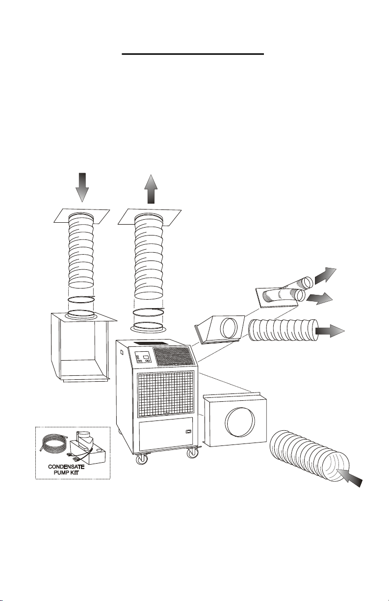
CONDENSATE TANK/PUMP
2OAC units come equipped with a means for handling the condensate generated
during the cooling process. All units, except the 5-ton models, come equipped with a
condensate tank. The tank can be easily removed from the unit and emptied as needed.
The 2OAC60 models come equipped with an automatic condensate pump. The pump
comes with a 20 foot long vinyl hose that allows for the removal of the condensate water
to a drain. The automatic pump is capable of a 20ft vertical lift, to handle almost any
installation requirement.
FILTERS
All 2OAC units are equipped with washable filters at the air intakes. Electrostatic mesh
air filters located behind the evaporator return air grille serve to filter the air before it is
cooled, and behind the condenser return air grille to prevent dust build-up. Both filters
can be easily removed and cleaned.
HIGH PRESSURE SAFETY SWITCH
Located on the back of the 2OAC unit is a manual re-set high pressure switch, used for
the protection of the compressor. If the condensing pressure exceeds the limit setting,
the switch will cycle the compressor off, while the evaporator fan remains running. The
display will indicate the default setting “CON”. The compressor can then be re-started,
once the condensing pressure has equalized, by depressing the “RESET” button.
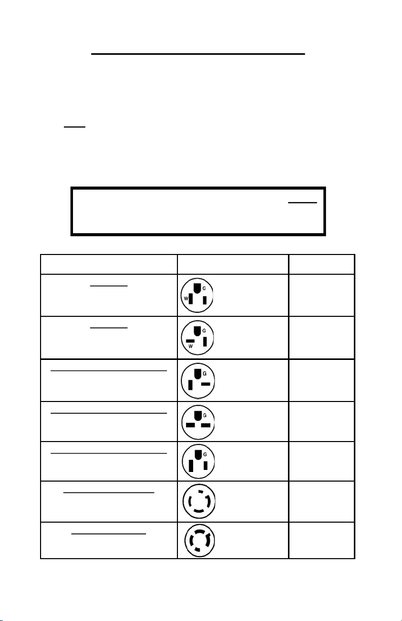
POWER CORDS
All 2OAC units come standard with a power cord for a convenient connection. All
models, except for the 3-phase units and 5-ton units, are equipped with a LCDI for
added safety features.
3

4
APPLICATIONS
COOLING MODE—SPOT COOLER
The 2OAC can be used in an open environment to cool specific objects or "spots". Spot
Cooling is a convenient and economical way to provide air conditioning, where cooling
the entire space is impractical. Cool air is discharged from the unit and is directed where
it is needed. Nozzle kits can be used for directional cooling.
AREA COOLER
When the 2OAC is installed in an open area, the condenser exhaust duct directs the
warm air away from the space, allowing the evaporator air to cool the specific area.
ROOM AIR CONDITIONER
When ducted properly, the 2OAC can be used as a room air conditioner to cool an
enclosed space. Using the condenser return air plenum, additional ceiling kit, the 2OAC
can then operate as a room air conditioner with the condenser air isolated from the
conditioned space.
CONDENSER AIR
INLET
(Back of Unit)
OUTDOOR FAN DISCHARGE
“HOT”
WASHABLE
GRILLE
AND FILTER
ELECTRONIC
CONTROLLER
INDOOR FAN
SUPPLY AIR
“COOL”
2OAC—COOLING MODE
2OAC—COOLING MODE OPERATION / DESCRIPTION
EVAPORATOR
RETURN

5
ELECTRICAL CONFIGURATION
All 2OAC-Series units are equipped with a standard 10-foot long service cord with plug
configurations and receptacle requirements as shown in this chart. 2OAC1211,
2OAC1811, 2OAC2412 and 2OAC3612 units come with LCDI (Leakage Current
Detection & Interruption) devices that serve as a means of electrical protection.
CAUTION
DO NOT USE THE LCDI AS AN ON/OFF SWITCH FOR THE UNIT
All 3-phase models are equipped with locking plugs for added connection reliability.
Refer to the chart below for plug and receptacle details for all 2OAC models.
A DAMAGED LCDI POWER SUPPLY CORD MUST
BE REPLACED WITH A NEW POWER SUPPLY
CORD AND NOT REPAIRED
UNIT/MODEL PLUG CONFIGURATION RECEPTACLE
115 VOLT
2OAC1211
NEMA 5-15R
115 VOLT
2OAC1811
NEMA 5-20R
208-230 VOLT SINGLE PHASE
2OAC2412
NEMA 6-20R
208-230 VOLT SINGLE PHASE
2OAC3612
NEMA 6-30R
208-230 VOLT SINGLE PHASE
2OAC6012
NEMA 6-50R
208-230 VOLT 3-PHASE
2OAC3632
2OAC6032
NEMA L15-30R
460 VOLT 3-PHASE
2OAC3634
2OAC6034
NEMA L16-20R
15A-125 VOLT
NEMA 5-15P
20A-125 VOLT
NEMA 5-20P
20A-250 VOLT
NEMA 6-20P
30A-250 VOLT
NEMA 6-30P
50A-250 VOLT
NEMA 6-50P
30A-250 VOLT
NEMA L15-30P
20A-460 VOLT
NEMA L16-20P

6
USE OF EXTENSION CORDS
CAUTION
FOR MODEL 2OAC1211 AN EXTENSION CORD CAN BE USED, PROVIDED
IT IS RATED AT LEAST 15 AMPS @ 115 VOLTS WITH GROUNDING-TYPE
ATTACHMENT PLUG AND GROUNDING TYPE CONNECTOR (LOAD FITTING)
FOR MODEL 2OAC1811 AN EXTENSION CORD CAN BE USED, PROVIDED
IT IS RATED AT LEAST 20 AMPS @ 115 VOLTS WITH GROUNDING-TYPE
ATTACHMENT PLUG AND GROUNDING TYPE CONNECTOR (LOAD FITTING)
FOR MODEL 2OAC2412 AN EXTENSION CORD CAN BE USED, PROVIDED
IT IS RATED AT LEAST 20 AMPS @ 250 VOLTS WITH GROUNDING-TYPE
ATTACHMENT PLUG AND GROUNDING TYPE CONNECTOR (LOAD FITTING)
FOR MODEL 2OAC3612 AN EXTENSION CORD CAN BE USED, PROVIDED
IT IS RATED AT LEAST 30 AMPS @ 250 VOLTS WITH GROUNDING-TYPE
ATTACHMENT PLUG AND GROUNDING TYPE CONNECTOR (LOAD FITTING)
FOR MODEL 2OAC6012 AN EXTENSION CORD CAN BE USED, PROVIDED
IT IS RATED AT LEAST 50 AMPS @ 250 VOLTS WITH GROUNDING-TYPE
ATTACHMENT PLUG AND GROUNDING TYPE CONNECTOR (LOAD FITTING)
FOR MODELS 2OAC3632 AND 2OAC6032 AN EXTENSION CORD CAN
BE USED, PROVIDED IT IS RATED AT LEAST 30 AMPS @ 250 VOLTS, 3 PHASE
FOR MODELS 2OAC3634 AND 2OAC6034 AN EXTENSION CORD CAN
BE USED, PROVIDED IT IS RATED AT LEAST 20 AMPS @ 600 VOLTS, 3 PHASE
SPECIAL NOTICE—THREE PHASE OPERATION
Models 2OAC3632, 2OAC3634, 2OAC6032 and 2OAC6034
All three-phase 2OAC models are equipped with a three-phase monitor for added com-
pressor protection. The phase monitor, located in the control box, has a multi-color
LED that reports status. The monitor protects the compressor from reverse operation,
phase loss, and low voltage situations. Further description of the three-phase monitor
is located in the electrical section of this manual.
NOTICE - DO NOT OPERATE ANY THREE-PHASE UNIT WHILE BYPASSING
THE MONITOR. THIS WILL VOID THE WARRANTY.

7
This Side Up
FRONT
CONDENSATE TANK
“FULL” SWITCH
SPRING
CAP
HANDLE
WATER LEVEL
ADJUSTMENT
SCREW
HINGE
CONDENSATE TRAY
TANK LEVEL ADJUSTMENT INSTRUCTIONS
An adjustment screw is provided to vary the cut-off level of
the tank full switch. If less water is desired, turn the adjusting
screw clockwise (CW).
Turning the screw clockwise (CW),
will make the tank easier to remove.
MAXIMUM WATER LEVEL
4” FROM TOP OF TANK
CAUTION
UNPLUG UNIT BEFORE REMOVING
TANK TO ADJUST THE SET SCREW.
CONDENSATE
SUMP
TOP OF TANK
(WHEN PLACED IN UNIT)
SUMP DRAIN HOLE
“CON” WILL BE
DISPLAYED
CONDENSATE
For Models 2OAC1211, 2OAC1811, 2OAC24 and 2OAC36, a 5-gallon polyethylene tank
is provided to collect condensate. The tank is located in the lower front section of the unit,
and can be accessed though the condensate tank door. When the high water level is
reached, a cut-out switch will AUTOMATICALLY cycle off the compressor/condenser fan.
MAXIMUM
WATER LEVEL
4” FROM TOP
OF TANK

8
NOTE - IT IS IMPORTANT TO SPECIFY MODEL NUMBER
AND SERIAL NUMBER WHEN ORDERING ACCESSORIES
2OAC ACCESSORIES
CONDENSER
DISCHARGE
CONDENSER
RETURN
NOZZLE KIT
ROUND FLEX-DUCT
(SOLD SEPARATELY)
ROUND FLEX-DUCT
(SOLD SEPARATELY)
EVAPORATOR
RETURN AIR
PLENUM
CONDENSER
RETURN AIR
PLENUM
DISCHARGE DUCT
ADAPTER
CEILING
PANEL
KIT
(CK)
CEILING
PANEL
KIT
(CK-PL)
*NOTE: 2OAC36 and 2OAC60 come with 16” duct flanges.
DUCT
FLANGE

9
2OAC ACCESSORIES
NOZZLE KIT
2NK-1 (2 X 4-Inch) 2OAC12
2NK-2 (2 X 6-Inch) 2OAC18, 24
2NK-3 (2 X 8-Inch) 2OAC36, 60
EVAPORATOR RETURN AIR PLENUM
DEP-10 (10-Inch Round) 2OAC12
2DEP-12 (12-Inch Round) 2OAC18, 24
DEP-16 (16-Inch Round) 2OAC36, 60
DISCHARGE DUCT ADAPTER
2DDA-6 (6-Inch Round) 2OAC12
2DDA-10 (10-Inch Round) 2OAC18, 24
2DDA-16 (16-Inch Round) 2OAC36, 60
CONDENSATE PUMP KIT *
2DPC-1115V Models
2DPC-2230V Models
* Not Required for 2OAC60’s
CEILING PANEL KIT
(Includes Panel, Duct, Strap and Flange)
CK-12 Kit for 2OAC12, 18, 24
CK-16 Kit for 2OAC36, 60
CK-12PL CK-12 without Duct Flange
CKP-12 2 X 2 Ceiling Panel only
CKP-16 2 X 2 Ceiling Panel only
DUCT FLANGE
DF-12 12-Inch Duct Flange
DF-16 16-Inch Duct Flange
NOTE: 2OAC36 and 2OAC60 units come with
16” duct flanges installed.
CONDENSER RETURN AIR PLENUM
2DCP-12OAC12
2DCP-22OAC18, 24
DCP-52OAC36, 60

ACCESSORIES
CEILING PANEL DUCT KIT
A ceiling panel kit is available for discharging the
condenser air above a drop ceiling. The ceiling
panel duct kits are furnished with a white vinyl
coated flexible duct that allows for convenient
installation. A 2ft X 2ft ceiling duct- panel is
included to replace a 2ft X 2ft drop-ceiling panel
where the connection is desired.
The CK-12 is available for 2OAC12, 18, and
24. The ceiling panel kit consists of 8 feet of
flexible duct, a 2' X 2' lay in ceiling panel and a
12 inch duct flange that attaches to the
condenser air discharge opening on the top of
the unit. The CK-16 (for 3 and 5-ton units)
consists of a ceiling duct-panel, and a 16 inch
flexible duct.
Note—Drop ceiling spaces should be
vented or large enough to handle the warm
condenser air. Check local codes to assure
compliance.
If longer runs of duct are required, table below
lists maximum duct run with no bends. For every
90° elbow, subtract 6 feet from the run.
Ceiling
Kit
Model
Flexible Duct
Diameter X
Length
Fits
2OAC12
Fits
2OAC18
Fits
2OAC24
Fits
2OAC36
Fits
2OAC60
CK-12 12 inch X 8 feet ✓✓✓No No
CK-16 16 Inch X 8 feet No No No ✓✓
25
(.20)
50
(.25)
50
(.25)
50
(.25)
100
(.50)
Maximum Equivalent
Feet (approx)
(ESP)
2 x 2 CEILING
DUCT-PANEL
VINYL COATED
FABRIC DUCT
DUCT FLANGE
DUCT STRAP
DUCT FLANGE
The optional duct flange allows for round flexible ducting to be
attached to the 2OAC condenser discharge. DF-12
(12-inch diameter) fits all units except the 3 ton/5 ton. The
DF-16 (16 inch diameter) fits the 3 ton model 2OAC36,
and 5 ton Model 2OAC60.
NOTE: 2OAC36 and 2OAC60 units come with
duct flange installed.
10

11
ACCESSORIES
DISCHARGE AIR NOZZLE KIT ASSEMBLY
The optional discharge nozzle kits are used to direct the
conditioned air to a specific target area. By concentrating the
airflow, the nozzles increase the air velocity towards production
lines to cool personnel and/or equipment. In server rooms, the
nozzles can be used to direct the airflow through the rack, and
remove the hot air from the equipment area.
2NK-1 for model 2OAC12, with (2) 4-inch diameter nozzles with
an approximate compressed length of 15 inches. The approximate
extended length is 21 inches.
2NK-2 for models 2OAC18 and 2OAC24 with (2) 6-inch
diameter nozzles with an approximate compressed length of 22
inches. The approximate extended length is 32 inches.
2NK-3 for 2OAC36 and 2OAC60, with (2) 8-inch diameter
nozzles with an approximate compressed length of 20 inches. The
extended length is approximately 29 inches.
The nozzle kits come pre-assembles with the nozzles secured to a
mounting plate, and with edge guards. By removing the
2OAC discharge grille, you can insert the nozzle kit into the
opening without the use of tools.
Nozzle Kits
Kit Voltage
2DPC-1 115V
2DPC-2 208-230V
(2OAC60 models come with
pump installed)
CONDENSATE PUMP KIT
A plug-in condensate pump kit is available for applications where emptying the 5 gallon
condensate tank is not practical. The pump kit consists of a condensate pump with
mounting hardware and electrical connections, along with the tubing required for the drain
and discharge of the condensate water.
PARTS LIST
(1) Condensate Pump with mounting hardware
(1) 3/8-inch drain hose, 20 ft
(2) Mounting screws
(1) Drain hose — black corrugated
(2) Hose clamps
The condensate pump provides for the automatic
removal of condensate water during the cooling
process. The pump is capable of pumping to a 20
foot height, allowing for the routing of the drain line
above the drop-ceiling to a nearby drain. The pump
is controlled by an internal float-switch/check valve,
which turns the pump on and off automatically. The
pump is also equipped with a condensate over-flow
safety switch, that will cycle the compressor off when
the pump is not working properly.

ACCESSORIES
CONDENSER RETURN AIR PLENUM
Condenser return air plenums are available for installations where it is required to duct air
to the inlet of the condenser. The plenum easily fits into place on the back of the unit,
and is provided with a flange for connecting 12-inch or 16-inch flexible ducting. A con-
denser return air plenum can substantially reduce air noise and allow the unit to operate
without drawing condenser air from the conditioned space. Refer to the table below for
configuration and application information.
NOTE — When installing the condenser return air plenum with a ceiling panel kit,
allow for a minimum separation distance of 2 feet between the unit discharge duct
and the return air duct. It is also recommended to direct the condenser discharge
air away from the condenser return air duct.
Plenum
Kit Duct
Flange
2OAC12 2OAC18 2OAC24 2OAC36 2OAC60
2DCP-1 12-inch ✓
2DCP-2 12-inch ✓ ✓
DCP-5 16-Inch ✓ ✓
Maximum Approximate
Equivalent Feet
25 50 50 50 100
Estimated External
Static Pressure (.20) (.25) (.25) (.25) (.50)
2DPC-1, 2DCP-2, DCP-5
To estimate the “equivalent feet” of condenser duct,
add the length of the condenser intake duct run and the length of the
condenser discharge duct run, and add 6 equivalent feet per bend in the
duct. Make sure that you do not exceed the rated E.S.P. to avoid shut
down due to the high pressure cut-out.
12

13
Plenum Kit
Duct/
Flange
2OAC12 2OAC18 2OAC24 2OAC36 2OAC60 FILTERS
DEP-10
10 inch ✓ (1) 10”X20”X1”
2DEP-12
12 inch ✓ ✓ (1) 16”X24”X1”
DEP-16
16 inch ✓ ✓ (1) 10”X30”X1”
(1)15”X30”X1”
Maximum
Equivalent
Feet
25 50 50 50 100
Estimated
External
Static
Pressure
(.20) (.25) (.25) (.25) (.50)
ACCESSORIES
EVAPORATOR RETURN AIR PLENUM
Evaporator return air plenums are available for installations where it is required to duct air
to the inlet of the evaporator. The evaporator return air plenums allow the user to connect
round duct (flexible or rigid) to the return air intake to reduce air noise and increase the
number of options for solving difficult application problems. The plenum attaches to the
front of the unit, replacing the return air grille. Refer to the table below for configuration
and application information.
DEP-10 for 2OAC12 transitions the return air opening to a 10-inch round duct.
2DEP-12 for 2OAC18 & 2OAC24 transitions the return opening to a 12-inch round
duct.
DEP-16 for 2OAC36, 60 transitions the return opening to a 16-inch round duct.
NOTE—When an evaporator return air plenum is installed, it is recommended to set
the evaporator blower speed to high, to avoid coil freeze-up.
FILTER(S)
EVAPORATOR
RETURN AIR PLENUM

ACCESSORIES
DISCHARGE DUCT ADAPTER
Discharge duct adapters are available for applications where ducted evaporator
discharge is required. The adapters can be easily installed on the unit without
fasteners, and can be used for either vertical or horizontal ducting. The standard
discharge grille is removed and the 2DDA is attached in the grille opening.
2DDA-6 for model 2OAC12, converts the evaporator discharge to a 6-inch
diameter round duct.
2DDA-10 for models 2OAC18 and 2OAC24, converts the evaporator
discharge to a 10-inch diameter round duct.
2DDA-16 for models 2OAC36 AND 2OAC60, converts the evaporator
discharge to a 16-inch round duct.
When used in conjunction with the evaporator return air plenum, the unit can provide a
closed-loop cooling solution for a given space without the influence of any outside air.
Adapter
Model
Round
Duct
Size
2OAC12 2OAC18 2OAC24 2OAC36 2OAC60
2DDA-66-inch ✓
2DDA-10 10-inch ✓✓
2DDA-16 16-inch ✓✓
Maximum
Approx.
Equivalent Feet
25 50 50 50 100
Maximum
E.S.P .15 .25 .25 .25 .50
14

15
INSTALLATION INSTRUCTIONS
RECEIVING—INSPECTION
Upon receiving your 2OAC unit, inspect the packaging for any damage. All units are
shipped on a skid, and packaged in a triple-wall carton for added protection.
BEFORE INSTALLING
Check the unit for any damage. All OceanAire products are thoroughly inspected at the
factory and carefully packaged. If any damage is evident, contact OceanAire
IMMEDIATELY.
ELECTRICAL REQUIREMENTS
Check the nameplate located on the back of the unit to confirm the proper power is
available for the unit. Refer to "Specifications" section for voltage and amperage
requirements. For proper NEMA receptacles, refer to "Electrical service plug
configuration". When using extension cords, use the proper gauge cord, and check cord
voltage to the unit.
TIME DELAY FUSES/CIRCUIT BREAKERS ARE RECOMMENDED
WARNING—OPERATING THE UNIT ON IMPROPER
VOLTAGE WILL VOID THE WARRANTY
ACCESSORIES
Verify that all accessories are correct for the model, and are installed in accordance with
all instructions.
START-UP
Install the unit in accordance with all local and state building codes, and install all
accessories. Allow for a clearance around the unit for future maintenance and/or service.
Level unit and lock casters, when available. Connect power and test the LCDI on the
power cord (if available). Power up unit, via thermostat and check for proper operation.
Refer to Thermostat Operation for more details.

16
OCEANAIRE DELUXE ELECTRONIC CONTROLLER
When power is connected, the controller will display “888” momentarily, and will then
disappear. Press the POWER button, then press the TEMP SELECT button until the
SET POINT is displayed. Adjust the SET POINT to the desired temperature, and the
unit will cool as programmed.
The systems controls temperature within +/- 2°
POWER—Turns the unit on/off when power is supplied
MODE - Select the Cool or Moisture Control
COOL - The system will operate in cooling mode, only
MOISTURE CONTROL - The system operates in the cooling mode to reduce
humidity within the conditioned space. Every 4 hours, the fan is started, circulating the
air, and the air temperature is recorded by the controller. The cooling cycle is started for
one hour, or until the room temperature drops 2°, which ever comes first. This cycle
repeats every four hours.
DELUXE ELECTRONIC CONTROLLER
The 2OAC controller is equipped with many features for a more precise level of cooling
and operation. Additionally, the controller can be removed from the unit and installed for
remote operation, if needed (accessory parts may be required).
POWER
button

17
CONTROLLER PROGRAMMING MENU
1) Make sure the unit has power .
2) Press the power button “OFF”.
3) Press the following buttons in sequence “S-U-D-S”
(Select—Up arrow — Down arrow — Select)
4) The display will begin flashing P1 and a number.
If there is no
display, repeat the sequence,
making sure the unit has power, but is turned OFF.
5) To adjust any program feature, press the ARROW UP▲ or ARROW DOWN ▼ button
until the desired value is displayed.
6) Use the “MODE” button to scroll through the programmable settings P1 through P16.
7) If no buttons are pressed, the display will then return to the “OFF” position after about
50 seconds.
PROGRAM SETTINGS
P1—High Fan Speed Limit Setting. 56 - 85
P2—Low Fan Speed Limit Setting, 30 - 55
P4—Temperature Sensor Calibration, +/- 10°
P10— Temperature Display, °F or °C
P13—Supply Fan Operation, Cycling or Continuous
P15—Fan Motor Type Setting, PSC or Shaded Pole
P1, P2 - To adjust fan speed settings, P1 represents the high fan speed parameter, while
P2 represents the low fan speed parameter. When using nozzle kits, discharge duct
adapters and evaporator plenums, setting P1 to 85 will help to avoid freeze ups.
P4 - Adjust the P4 setting to match the actual INSIDE room temperature, if needed.
P10 - Use this parameter to display temperatures in the desired units.
P13 - To cycle the evaporator fan with the compressor, access code P-13. Press the up
or down button to switch to “CYC”, which means cycle the fan with the compressor. The
factory default setting is “CON”, which means continuous fan operation.
P15 - Fan Motors are PSC type, SC - should be selected.
8) Press POWER — you should see an alphanumeric code.
Press POWER and the unit will start at the new settings
FAN SPEED—The operator can select between AUTO or MANUAL fan speed con-
trol. Pressing the FAN SPEED button, will switch speed from AUTO to MANUAL. In
MANUAL mode, pressing the FAN SPEED button will change fan speed from low to high.
In AUTO mode, the fan speed is controlled automatically. In cooling mode, the controller
automatically adjusts the fan speed to high, and as the inside temperature approaches
the set point, the fan speed will reduce.
TEMP SELECT— Allows the operator to view the controller temperatures
INSIDE = return air temperature, DISCHARGE = supply air temperature,
SET POINT can be seen and adjusted, by pressing ▲ or▼.

DISPLAY FAULTS
LAC……… Low AC line power
AAA……… Failed Air Sensor (unit will not run)
CON……… Empty Condensate Bucket—Units with a bucket
Condensate Pump Over-Flow Alarm—Units with pump
High Pressure Cut-Out—Restricted air flow
correct problem, and re-set unit at HP RESET
TO CHECK THE NUMBER OF HOURS ON THE UNIT
1) Disconnect unit power, and reconnect unit power.
2) When “888” appears in display, push and release the arrow down button
3) The first set of numbers displayed reads thousands of hours:
02 = 2000, 04 = 4000 hours, 00 means less than 1000 hours.
4) The second set of numbers read hours directly:
58 = 58 hours. 742 = 742 hours.
6) Add the 2 number sets together to get total hours.
03 and 486 = 3486 hours. 01 and 59 = 1059 hours.
TOTAL HOURS REPRESENTS COMPRESSOR “RUN” TIME
MODEL CODE SETTINGS
2OAC12 P1 = 65, P2 = 45
2OAC18 P1 = 80, P2 = 50
2OAC24 P1 = 70, P2 = 50
2OAC36 P1 = 85, P2 = 40
2OAC60 P1 = 85, P2 = 45
2OAC PROGRAM SETTINGS
NOTICE
Program Parameters are NOT controller default values.
They are OceanAire Factory Settings
18
This manual suits for next models
9
Table of contents
Other OCEANAIRE Accessories manuals
Popular Accessories manuals by other brands

Panasonic
Panasonic KX-HNS101 installation guide

HomeAware
HomeAware BLINK HA360B user guide

Sandberg
Sandberg 24000 quick guide

Panasonic
Panasonic MA3S132DG Specification sheet

Thule
Thule Rain Blocker G2 instructions

Ingenieurbüro Mencke & Tegtmeyer
Ingenieurbüro Mencke & Tegtmeyer Si-RS485TC-T-MT Quick reference guide