OCEANAIRE PWC Series User manual

ENGINEERING, INSTALLATION AND SERVICE MANUAL
PWC series
Portable Water-Cooled
Spot Cooler
EISM-PWC 10012021

FORWARD
This manual provides the user with basic details for the installation and operation
of the OceanAire PWC spot cooler. It is recommended to read and fully understand
the instructions outlined within this manual, before operating the PWC unit.
As with all commercial air conditioning equipment, it is recommended to have the
PWC sized and installed by a licensed specifying engineer and contractor, in ac-
cordance with all local and state codes. The length of service received can be
extended by following the installation and preventive maintenance instructions.
NOTICE
In our ongoing process of continuous improvement, the items and procedures de-
scribed in this manual are subject to change without notice. Please note model and
serial number of the PWC unit when contacting the factory.
TABLE OF CONTENTS
PAGE
GENERAL INFORMATION….................................... 1
PRODUCT DATA AND SPECIFICATIONS............ 2
UNIT DESCRIPTION
Standard Features.................................. 3
Applications / Operation...................... 4
Electrical Configurations..................... 5
Use of Extension Cords......................... 6
Accessories………...................................... 7 - 11
Options / Special Order........................ 12
Installation............................................... 13
Thermostat…………..................................... 14
SERVICE
Water Valve Adjustment………………...... 15
Unit Interior………………………………………….. 16
Replacement Parts Procedure............ 17
Troubleshooting Guide......................... 18
Preventive Maintenance...................... 19-20
DIAGRAMS
Piping Schematic..................................... 21
Single Phase Wiring Diagrams………….. 22-23
Three Phase Monitor............................... 24
Three Phase Wiring Diagrams.............. 25 - 27
WARRANTY…………………………………………………………..….. 28
TECH NOTES…………………………………….…………………….... 29
END USER INFORMATION …………………………………... Back Page

GENERAL INFORMATION
The OceanAire PWC is a portable water-cooled air conditioner designed for perma-
nent or temporary spot cooling applications. The entire air conditioning unit has
been built in an attractive sheet metal cabinet, equipped with heavy-duty casters
for mobility. All PWC models come with a 10-foot power cord for electrical connec-
tion and added mobility in service. These spot-coolers are designed to direct air to
specific areas or objects through a discharge grille located on the upper-front of the
unit. The PWC models range in cooling capacities from 12,000 BTU/HR to 60,000
BTU/HR to satisfy most space cooling requirements.
The PWC is a self-contained unit with the entire cooling system (blower assembly,
electrical, refrigerant, and waterside components), neatly arranged in a gray
polyester powder coated metal cabinet. When connected to the proper source of
electrical power, a 24-volt thermostat controls the PWC unit to provide the desired
level of comfort and cooling.
A wide variety of accessories and factory installed options are available for the
PWC units allowing for improved performance and versatility.
1
NOMENCLATURE
P WC 36 1 2
PORTABLE VOLTAGE
(1—115v; 2—230v; 4-460v)
WATER-COOLED
PHASE (1 or 3)
NOMINAL CAPACITY
CAPACITY RATING
12..........12,000 BTU/HR
18..........18,000 BTU/HR
24.........24,000 BTU/HR
36.........36,000 BTU/HR
60….…...60,000 BTU/HR
NOT APPROVED FOR OUTDOOR USE
WARRANTY
All Oceanaire Products are covered
by the Oceanaire Limited Warranty
1 YEAR ON THE FULL PRODUCT
Plus, 4 additional years for the compressor
(Restrictions Apply)
WARRANTY CARD
It is important that the warranty card be filled out completely and returned to the
factory within fourteen (14) days of installation of the unit in order to receive the
benefits of the warranty.

PWC
SPECIFICATIONS
2
MODEL: PWC 1211 1811 2412 3612 3632 3634 6012 6032 6034
COOLING CAPACITY 12,000 18,000 23,950
VOLTAGE (V/Phase) at 60Hz 208-230/3 460/3 208-230/1 208-230/3 460/3
UNIT AMPS 8.1 11.3 9.9 12.0 9.3 4.7 23.7 16.5 6.3
UNIT WATTS 930 1300 2100
IN-RUSH CURRENT (AMPS) 56 69 55 100 80 48 165 149 75
PLUG TYPE 5-15P 5-15P 6-20P 6-20P L15-20P L16-20P 6-30P L15-30P L16-20P
EER 12.9 13.8 11.4
COMPRESSOR HP 1 1 1/2 2
COMPRESSOR LRA 50 63 48 83 77 35 158 137 62
EVAP CFM 400 600 810
EVAP MOTOR HP
COND GPM @ EWT, 60°F INLET 0.75 1.1 1.55
COND GPM @ EWT, 85°F INLET 3 4.5 6
WATER VALVE CONNECTION
DRAIN (RETURN) CONNECTION
CONDENSATE PUMP (ALL UNITS)
R-410A CHARGE (oz.) 14 18 20
HEIGHT (in.) 33.8
WIDTH (in.) 20.1
DEPTH (in.) 13.1
NET WEIGHT (lb.) 125 155 170 310 410
PWCSPECS10012021
44.8
16.0
275
2.2
3.8
375
29.1
19.5
28.1
52.5
52
24
27.1
50.2
20 FT LIFT - 3/8 MF CONNECTION ON UNIT - DRAIN
20.6
60,100
36,100
2700
5000
3
5
13.4
12.0
115/1
1200
1950
208-230/1
3/8 MF
5/8 MF
5/8 MF
3/8 MF
15
9
1/8
1/3
1
SPECIFICATIONS SUBJECT TO CHANGE WITHOUT NOTICE
Cooling capacity is total BTUH at 80ºDB/67ºWB return air,
High fan speed, with 85ºEWT to 95ºLWT (4.5 GPM)
Time delay fuses/circuit breakers are recommended
EER is determined at High fan speed
CFM with free discharge
Amps and Watts at 115/208/460 volts
COOLING AMBIENT OPERATING RANGE 65º to 105º
NOT APPROVED FOR OUTDOOR USE

STANDARD FEATURES
CABINET
The PWC-Series cabinet is constructed of 18 gauge steel with a gray
polyester powder coated finish that will compliment any decor. The entire cabinet is
insulated with sound- absorbing insulation for cool, quiet comfort. All units come
equipped with handles and swivel casters for portability and convenient set-up.
ELECTRONIC THERMOSTAT
All PWC units are equipped with a non-
programmable electronic thermostat. When power is connected to the unit, the thermo-
stat will control the unit to cool a space to the desired temperature. The thermostat is
also capable of controlling the fan to operate automatically (when needed) or continuous-
ly. To protect the compressor from short-cycling, there is a built-in time delay in the
thermostat. In the event of a power outage, all thermostat settings are saved, and the unit
will re-start automatically.
FAN SPEED CONTROL
A two position rocker switch, located near the thermostat,
provides the user with the option of running the evaporator fan at high-speed or
low-speed.
CONDENSATE PUMP
All PWC units come equipped with an Automatic Condensate
Pump that removes the condensate. The pump discharges through a check valve located
on top of the condensate pump assembly. The vinyl tubing exits through a 3/8” male flare
fitting, located in the recessed area of the unit. The pump has capabilities up to a 20’ lift,
to handle almost any installation requirement. If a failure occurs with the operation of
the pump circuit, the NC overflow switch will open, and the CONDENSATE ALARM warn-
ing light will energize. When the failure has been corrected, or the condensate line block-
age/kink has been resolved, the alarm light will clear, and the unit will restart.
CONDENSATE ALARM LIGHT
On the front of all PWC models, there is a Conden-
sate Alarm Light (RED) located near the thermostat. The light indicates a condensate
pump over-flow condition where the pump is either disabled, or incapable of removing
the condensate water, and must be serviced.
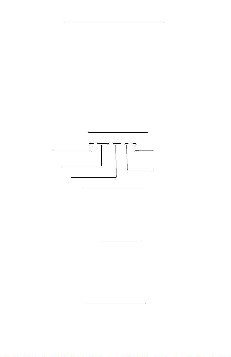
FILTERS
All PWC units are equipped with a washable filter at the air intake. An elec-
trostatic mesh air filter is located behind the evaporator return air grille to filter the air
before it is cooled, keeping the coil free from debris. The filter can be easily removed and
cleaned.
HIGH PRESSURE SAFETY SWITCH
Located near the hose fittings of the PWC
unit is a manual re-set high pressure switch, used for the protection of the compressor in
the event that the condenser water supply is turned off. If the condensing pressure
exceeds the limit setting, the switch cycles off the compressor, while the evaporator fan
continues to operate. Once the water interruption has been corrected, turn the unit off,
RESET THE RED BUTTON by pushing down on the rubber boot in the recessed area of the
unit, listening for the click, and restart the unit.
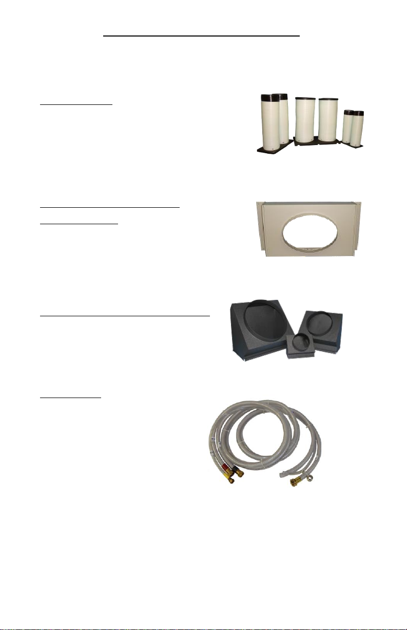
POWER CORDS
All PWC units come with power cords, convenient connection and
portability. All models, except for the 3-phase and 5-ton units, are equipped with LCDI for
added safety devices.
3

4
RETURN
AIR
INLET
EVAPORATOR FAN
DISCHARGE
“COOL”
GRILLE
AND WASHABLE
FILTER
THERMOSTAT
DRAIN
WATER IN
WATER OUT
FAN SPEED
SWITCH
APPLICATIONS
SPOT COOLER
The PWC can be used in an open environment to cool specific objects or "spots".
Spot Cooling is a convenient and economical way to provide air conditioning
where cooling the entire space is impractical. Cool air is discharged from the unit
and is directed where it is needed. Nozzle kits can be used to improve direction of
the cooling airflow.
ROOM AIR CONDITIONER
One feature of the PWC is it operates as a room air conditioner because water is
used as the means for heat rejection. The major advantage of water-cooled air
conditioning is the convenience of connecting water hoses, or lines, as compared
to the installation of condenser air ducts used for air-cooled portables. A variety of
hose kit lengths are available that can be used for connecting to a water supply and
drain, while providing portability within the conditioned space.
PWC—OPERATION / DESCRIPTION

ELECTRICAL CONFIGURATION
All PWC Series units are equipped with a standard 10-foot long service cord with
plug configurations and receptacle requirements as shown in this chart. PWC1211,
PWC1811, PWC2412 and PWC3612 units come with LCDI (Leakage Current Detection
& Interruption) devices that serve as a means of electrical protection.
CAUTION
DO NOT USE THE LCDI AS AN ON/OFF SWITCH FOR THE UNIT
All 3-phase models are equipped with locking plugs for added connection reliabil-
ity. Refer to the chart below for plug and receptacle details for all PWC models.
A DAMAGED POWER SUPPLY CORD MUST BE REPLACED WITH A
NEW POWER SUPPLY CORD OBTAINED FROM
OCEANAIRE, AND NOT REPAIRED
5
UNIT/MODEL PLUG CONFIGURATION RECEPTACLE
115 VOLT
PWC1211
PWC1811
NEMA 5-15R
208-230 VOLT SINGLE PHASE
PWC2412
PWC3612
NEMA 6-20R
208-230 VOLT SINGLE PHASE
PWC6012
NEMA 6-30R
208-230 VOLT 3-PHASE
PWC3632
NEMA L15-20R
208-230 VOLT 3-PHASE
PWC6032
NEMA L15-30R
460 VOLT 3-PHASE
PWC3634
PWC6034
NEMA L16-20R
15A-125 VOLT
NEMA 5-15P
20A-250 VOLT
NEMA 6-20P
30A-250 VOLT
NEMA 6-30P
20A-250 VOLT
NEMA L15-20P
30A-250 VOLT
NEMA L15-30P
20A-460 VOLT
NEMA L16-20P

6
USE OF EXTENSION CORDS
CAUTION
FOR MODELS PWC1211 AND PWC1811 AN EXTENSION CORD CAN BE
USED PROVIDED IT IS RATED AT LEAST 15 AMPS @ 115 VOLTS WITH GROUND-
ING-TYPE ATTACHMENT PLUG AND GROUNDING TYPE
CONNECTOR (LOAD FITTING)
FOR MODELS PWC2412 AND PWC3612 AN EXTENSION CORD CAN BE
USED PROVIDED IT IS RATED AT LEAST 20 AMPS @ 250 VOLTS WITH GROUND-
ING-TYPE ATTACHMENT PLUG AND GROUNDING TYPE CONNECTOR (LOAD
FITTING)
FOR MODEL PWC6012 AN EXTENSION CORD CAN BE USED PROVIDED IT IS
RATED AT LEAST 30 AMPS @ 250 VOLTS WITH GROUNDING-TYPE ATTACH-
MENT PLUG AND GROUNDING TYPE CONNECTOR (LOAD FITTING)
FOR MODEL PWC3632 AN EXTENSION CORD CAN BE USED PROVIDED IT
IS RATED AT LEAST 20 AMPS @ 250 VOLTS, 3 PHASE
FOR MODEL PWC6032 AN EXTENSION CORD CAN BE USED PROVIDED IT
IS RATED AT LEAST 30 AMPS @ 250 VOLTS, 3 PHASE
FOR MODELS PWC3634 AND PWC6034 AN EXTENSION CORD CAN BE
USED PROVIDED IT IS RATED AT LEAST 20 AMPS @ 600 VOLTS, 3 PHASE
SPECIAL NOTICE—THREE PHASE OPERATION
Models PWC3632, PWC3634, PWC6032 and PWC6034
All three-phase models are equipped with a three-phase monitor for added com-
pressor protection. The phase monitor, located in the control box, has multi-
color LED that reports status. The monitor protects the compressor from reverse
operation, phase loss and low voltage situations. Further description of the three
-phase monitor is located in the electrical section of the manual.
NOTICE - DO NOT BYPASS THE THREE PHASE MONITOR. THIS
WILL VOID THE WARRANTY.

NOZZLE KIT
NK-1 (2 X 4-Inch) PWC12
2NK-2 (2 X 6-Inch) PWC18, 24
2NK-3 (2 x 8-Inch) PWC36, PWC60
EVAPORATOR RETURN
AIR PLENUM
DEP-10 (10-Inch Round) PWC12
2DEP-12 (12-Inch Round) PWC18, 24
DEP-16 (16-Inch Round) PWC36, 60
DISCHARGE DUCT ADAPTER
DDA-6 (6-Inch Round) PWC12
2DDA-10 (10-Inch Round) PWC18, 24
2DDA-16 (16-inch Round) PWC36, PWC60
HOSE KIT
HK-1 10FT PWC 12, 18, 24
HK-2 25FT PWC 12, 18, 24
HK-5 40FT PWC 12, 18, 24
HK-3 10FT PWC 36, 60
HK-4 25FT PWC 36, 60
HK-6 40FT PWC 36, 60
PWC Optional ACCESSORIES
7

8
ACCESSORIES
DISCHARGE AIR NOZZLE KIT ASSEMBLY
The optional discharge nozzle kits are used to direct the conditioned air to a
specific target area. By concentrating the airflow, the nozzles increase the air ve-
locity towards production lines to cool personnel and/or equipment. In server
rooms, the nozzles can be used to direct the airflow through the rack to remove the
hot air from the area of the equipment.
NK-1 for model PWC12, with (2) 4-inch diameter nozzles with an approximate
compressed length of 15 inches. The approximate extended length is 21 inches.
2NK-2 for models PWC18, PWC24 with (2) 6-inch diameter nozzles with an
approximate compressed length of 22 inches. The approximate extended length is
32 inches.
2NK-3 for model PWC36 , PWC60 with (2) 8-inch diameter nozzles with an
approximate compressed length of 20 inches. The approximate extended length is
29 inches.
The nozzle kits come pre-assembles with the nozzles secured to a mounting plate,
and with edge guards. By removing the PWC discharge grille, one can insert the
nozzle kit into the opening without the use of tools.
Nozzle Kits

9
ACCESSORIES
EVAPORATOR RETURN AIR PLENUM
Evaporator return air plenums are available for installations where it is required to duct
air to the inlet of the evaporator. The evaporator return air plenums allow the user to
connect round duct (flexible or rigid) to the return air intake to reduce air noise and
increase the number of options for solving difficult cooling problems. The plenum
attaches to the front of the unit, replacing the return air grille. Refer to the table below
for configuration and application information
DEP-10 for PWC12 transitions the return air opening to a 10-inch round duct.
2DEP-12 for PWC18 and PWC24 transitions the return opening to a 12-inch round duct.
DEP-16 for PWC36 and PWC60 transitions the return opening to a 16-inch round duct.
NOTE—When a DEP/2DEP is installed, it is recommended to set the evaporator blower
speed to high, to avoid evaporator coil freeze-up
.
Plenum Kit
Duct/
Flange
PWC12 PWC18 PWC24 PWC36 PWC60 FILTERS
DEP-10
10 inch ✓ (1) 10”x 20”x 1”
2DEP-12
12 inch
✓ ✓ (1) 16”x 24”x 1”
DEP-16
16 inch
✓ ✓ (1) 12”x 30”x 1”
(1) 10”x 30”x 1”
Maximum
Equivalent
Feet
25 50 60 70 80
Est. External
Static
Pressure
(.20) (.25) (.25) (.25) (.50)
FILTER(S)
EVAPORATOR RETURN
AIR PLENUM

10
ACCESSORIES
Discharge Duct Adapter
Discharge duct adapters are available for applications where ducted evaporator
discharge is required. The adapters can be easily installed on the unit without fas-
teners, and be installed for either vertical or horizontal ducting. The standard dis-
charge grille is removed and the DDA is attached in the grille opening.
DDA-6 for PWC12, converts the evaporator discharge to a 6-inch diameter round
duct.
2DDA-10 for PWC18 and PWC24, converts the evaporator discharge to a 10-inch
diameter round duct.
2DDA-16 for PWC36 and PWC60, converts the evaporator discharge to a 16-inch
diameter round duct.
When used in conjunction with the evaporator return air plenum, DEP, the unit can
provide closed-loop cooling to and from a given space without the influence of any
outside air.
NOTE—When a DDA/2DDA is installed, it is recommended to set the evaporator
blower speed to high, to avoid evaporator coil freeze-up
.
Adapter
Model
Round
Duct
Size
PWC12 PWC18 PWC24 PWC36 PWC60
DDA-6 6-inch ✓
2DDA-10 10-inch ✓✓
2DDA-16 16-inch ✓✓
Maximum Approx
Equivalent Feet 25 50 60 70 80
Maximum
E.S.P .15 .25 .25 .25 .50

11
ACCESSORIES
Hose Kit
Hose kits are available in lengths of 10, 25, and 40 feet. Each hose kit allows for
convenient installation of the PWC, while allowing for portability within the allow-
able space.
NOTE —When using these hoses in applications with water
pressures exceeding 50 PSIG, a water pressure reducing valve
must be installed in the water supply line prior to the hose kit;
otherwise warranty on the hose kits will be void.
All hose kits have FEMALE flare connectors to match the MALE flare fittings on the
units (see chart below). The WATER IN connector consists of a garden hose
connection. WATER OUT and DRAIN (condensate) have no fittings, and can be fed
to a sink or permanent drain. When using a hose kit, avoid sharp corners, hot water
pipes and kinking to assure proper water flow of the supply, return, and drain lines.
Hose
Kit Length
Flare Conn
IN-OUT-
DRAIN
PWC12 PWC18 PWC24 PWC36 PWC60
HK-1 10 ft 3/8 3/8 3/8 ✓✓✓
HK-2 25 ft 3/8 3/8 3/8 ✓✓✓
HK-5 40 ft 3/8 3/8 3/8 ✓✓✓
HK-3 10 ft 5/8 5/8 3/8 ✓✓
HK-4 25 ft 5/8 5/8 3/8 ✓✓
HK-6 40 ft 5/8 5/8 3/8 ✓✓
Included with the hose kit is a sink/faucet adapter

12
SPECIAL ORDER ITEMS
In some applications, units can be manufactured with optional components for
added performance and longevity. Below are a few of the PWC options that are
available.
Consult your distributor for pricing and availability.
CUPRO-NICKEL CONDENSER
When chemically treated water, salt water or brine, is used in the condenser coil, it
is recommended that the PWC be equipped with a 90/10 Cupro-Nickel condenser
coil.
HIGH PRESSURE WATER VALVE
For applications where water supply pressures exceed 150 psig, a high pressure
water regulating valve can be installed in the PWC. Valves designed for use with up
to 350 psig water inlet pressure are available.
HERESITE TREATED EVAPORATOR COIL
For use in chemically corrosive environments, the PWC can be manufactured with a
Heresite® dipped evaporator coil for improved coil life.
HOT GAS BYPASS VALVE
In applications where low evaporator temperatures may occur, an optional hot gas
bypass valve can be installed to regulate the evaporator temperature. The bypass
valve feeds refrigerant (hot gas) into the evaporator to avoid low ambient freeze-ups.
MARITIME WATER VALVE
Cast naval bronze body with MONEL parts. MONEL is a “natural alloy” and is highly
resistant to corrosion.
TOWER UNITS
In applications where the PWC is connected to a closed-loop condenser water cir-
cuit, a unit can be built for direct water connection WITHOUT a water valve.

13
INSTALLATION INSTRUCTIONS
RECEIVING—INSPECTION
Upon receiving your unit, inspect the packaging for any damage. All units are
shipped on a skid, and packaged in a triple-wall carton for added protection.
BEFORE INSTALLING
Check the unit for any damage. All OceanAire products are thoroughly inspected at
the factory and carefully packaged. If any damage is evident, contact OceanAire
IMMEDIATELY.
ELECTRICAL REQUIREMENTS
Check the nameplate located on the back of the unit to confirm the proper power is
available for the unit. Refer to "Specifications" section for voltage and amperage
requirements. For proper NEMA receptacles, refer to "Electrical service plug
configuration". When using extension cords, use the proper gauge cord, and check
cord voltage to the unit.
TIME DELAY FUSES/CIRCUIT BREAKERS ARE RECOMMENDED
WARNING—OPERATING THE UNIT ON IMPROPER
VOLTAGE WILL VOID THE WARRANTY
ACCESSORIES
Verify that all accessories are correct for the model, and are installed in
accordance with all instructions.
START-UP
Install the unit in accordance with all local and state building codes, and install all
accessories. Allow for a clearance around the unit for future maintenance and/or
service. Level unit and lock casters, when applicable. Connect power and test the
LCDI on the power cord (if equipped). Power up unit, via thermostat and check for
proper operation. Refer to Thermostat Operation for more details.

14
THERMOSTAT OPERATION
FAN SLIDE SWITCH
The FAN Slide Switch allow you to set the fan mode from ON (fan is on all the time)
to AUTO (fan cycles under thermostat control)
MODE SLIDE SWITCH
To turn the unit ON, slide the Mode Slide Switch down to the COOL position. To
turn the unit OFF, slide the Mode Slide Switch to the OFF Position.
TEMPERATURE BUTTONS
Once the MODE switch has been put into the COOL mode, push the corresponding
arrow button to lower or raise the set point to the desired temperature. The display
will show the set-point temperature with the word “SET” and will blink for 5
seconds. Then it will return to display the room temperature. After the delay has
timed out, the fan motor and compressor will start, beginning the cooling cycle.
Remember, the set-point must be lower than the room temperature for the unit to
start.
AUTO
ON
COOL
OFF
TEMPERATURE
CHANGE
BUTTONS
FAN
SLIDE
SWITCH
MODE
SLIDE
SWITCH
TEMPERATURE
DISPLAY
DIGITAL, NON-PROGRAMMABLE THERMOSTAT
This is a cooling only thermostat *. Select the temperature you want by pressing the
▲or ▼buttons.
No batteries are required. If there is a power failure, the thermostat will start up at the
last known set point, when the power is restored.
Compressor short cycle protection is a built-in feature of the thermostat. A 4-minute
time delay will occur on start-up or when power has been restored after a power
interruption.

15
WATER VALVE ADJUSTMENT
Each OCEANAIRE WATER-COOLED unit is equipped with an automatic water
regulating valve to control the condenser water flow rate. The water valve will open
when the unit is in the cooling mode and adjust the gallon per minute flow rate
based on the entering water temperature (EWT).
The water valve operates independently from the water system, and regulates flow
based on the systems refrigerant head pressure.
Under certain conditions, entering water temperatures can cause the valve to
rapidly open and close, causing a “harmonic” pitch in the water supply line. In these
cases, it is recommended that the water valve be adjusted.
1. Disconnect the unit power.
2. Remove water valve cover plate or back panel (depending on model) to
locate the water valve.
3. At the top of the valve, there is a square shaped adjustment screw. Using a
standard service wrench or flat blade screwdriver, adjust the valve using
quarter turns, allowing the unit to operate approximately 5 minutes after
each new setting.
• CLOCKWISE (CW) opens the valve, which lowers HIGH side pressure, and
lowers the valve’s set point to open.
• COUNTER-CLOCKWISE (CCW) closes the valve, which raises HIGH side
pressure, and raises the valve’s set point to open.
4. Re-install cover plate (or back panel) when finished.
Water Valve
Adjustment
Screw
Water Valve
Cover Plate

PWC INTERIOR
16
24v Electronic
Thermostat
Fan Speed
Rocker Switch
Hi/Lo
Condensate
Alert Light
Return Air Grille
Evaporator Filter
Front Locking
Casters
Compressor Run
Capacitor
High Pressure
Switch
Metal Strain
Relief
Water
Connections
Recessed Cubby
Rear Swivel
Casters
Evaporator
Blower Motor
Evaporator Coil
Compressor
Condensate
Pump
Evaporator
Discharge Grille

REPLACEMENT PROCEDURE FOR PARTS
IT IS RECOMMENDED THAT ALL OCEANAIRE UNITS BE SERVICED
BY A LICENSED TECHNICIAN
WARNING—TO AVOID INJURY, DISCONNECT UNIT POWER PRIOR
TO SERVICING
A. FAN MOTOR
1. Remove cabinet left-side panel (when looking at the front of the unit).
2. Evaporator fan motor—disconnect evaporator motor wires from evaporator fan
Contactor, fan speed rocker switch and run capacitor.
3.
For all model sizes 12, 18, 24, and 36
, remove the screws securing motor and
inlet-ring to blower housing (all screws are external and visible), and remove blower
wheel-motor assembly. Remove the blower wheel set screw and disassemble the
blower wheel from the motor shaft and remove the motor.
For model size 60
—loosen blower wheel shaft set screw, and remove the screws
securing the motor mount to the blower housing.
4. Install new motor/motor mount assembly, reversing the removal procedure for above
models.
5. For Model size 60, confirm motor is wired for proper rotation.
B. THERMOSTAT (NO BATTERIES REQUIRED)
1. Along both sides of the thermostat, insert a small flat blade screwdriver in the groove.
With a twisting motion, remove the cover plate from the sub base. Make sure the small
thermistor located near the top of the casing for temperature sensing, is not bent or
damaged.
2. To remove the thermostat sub-base, remove the 2 mounting screws and the 4 wires
(black, red, white, green). Make sure the 4 wires do not fall into the cabinet. Install
sub-base by reversing removal procedure.
C. CONDENSATE ALARM LIGHT
To replace the Condensate Alarm Light, disconnect the wires from the lamp and bend
the tinnerman clip retaining light and pull out. Install new light, reversing the
procedure.
D. CONDENSATE PUMP
1. Remove brackets securing condensate pump in base pan.
2. Disconnect pump wire leads at Molex connectors. Remove retainer clamp and tubing.
3. Replace pump, install by reversing procedure.
E. HIGH PRESSURE SAFETY SWITCH
While facing unit, to access high pressure switch.
1. Size 18 and 24, remove rear panel. All other sizes, remove right side panel.
2. Remove flare nut that secures capillary to the refrigeration system high pressure
side. A Schrader valve is located in the discharge port, which allows removal without
losing the refrigerant charge.
3. Remove two screws that secure high pressure switch.
4. Disconnect wire leads from compressor contactor and condensate pump safety
switch.
5. Install new High Pressure Switch, and splice in new wire leads with existing control
wires. Then reverse in order to complete procedure.
To gain access to compressor and compressor run capacitor, remove left side panel.
17

18
TROUBLESHOOTING GUIDE
The following steps and procedures are recommended for correcting the problems
indicated. In the event that the problem can not be corrected, service may be required.
SERVICE SHOULD BE PERFORMED BY A QUALIFIED AIR
CONDITIONING SERVICE TECHNICIAN
PROBLEM: UNIT DOES NOT POWER UP
CAUSE: Power interruption
REMEDY: Check LCDI (if equipped) and reset. Check external power supply making sure
that the disconnect is ON. Check for blown fuses or tripped circuit breakers. Reset or
replace (as needed).
PROBLEM: NO DISPLAY ON THERMOSTAT AFTER POWER “ON”
CAUSE: Loose thermostat wires, faulty thermostat or transformer/contactor.
REMEDY: Check connections, re-seat connectors. Thermostat may be defective...remove
and replace. Check transformer and/or contactor(s)...remove and replace.
PROBLEM: EVAPORATOR FAN RUNS BUT COMPRESSOR DOES NOT
START
CAUSE: Thermostat —set point is too high.
REMEDY: Make sure set-point is lower than room temperature.
Note—there is a time delay for the compressor
CAUSE: Thermostat—Loose thermostat wires
REMEDY: Examine the thermostat sub-base for corrosion, and/or loose thermostat wires.
CAUSE: Condensate Alarm Light
REMEDY: Check condensate pump and make sure pump is working properly and that
there is no kink in the drain line from the pump.
CAUSE: High Pressure Cut-Out. Inadequate/turned off condenser water supply.
REMEDY: Verify condenser water supply. Check High Pressure Cut-Out Switch.
Press Reset (RED Button, near hose connections). Re-start unit.
CAUSE: Supply Voltage. Check power supply for voltage outside the range
• 115 volt units (106-126)
• 208/230 volt units (187-253)
• 460 volt units (414-506)
REMEDY: Have power checked by electrician and repaired.
CAUSE: Transformer shows open coil circuit failure.
REMEDY: Replace line voltage/low voltage transformer.
CAUSE: Compressor Contactor failure
REMEDY: Replace compressor contactor.
CAUSE: Fan Contactor Failure
REMEDY: Replace fan contactor
This manual suits for next models
9
Table of contents
Other OCEANAIRE Accessories manuals
Popular Accessories manuals by other brands

Byron
Byron SX-14 Installation and operation instruction

air sniper
air sniper Induct 300W Standard instruction manual

natus
natus Jelly Tab Instructions for use

netvox
netvox RB11E user manual

PCB Piezotronics
PCB Piezotronics 208A22 Installation and operating manual

Panasonic
Panasonic MA3X787 (MA787) Specification sheet