Octagon 5420 User manual

NOTICE
The drivers and utilities for Octagon products, previously provided
on a CD, are now in a self-extracting zip file located at the Octagon
Systems web site on the product-specific page. Download this file to a
separate directory on your hard drive, then double click on it to extract
the files. All references in this manual to files and directories on the CD
now refer to files in the Utilities zip file.

5420 Super5420 Super
5420 SuperVV
VV
VGAGA
GAGA
GA Video CarVideo Car
Video CarVideo Car
Video Cardd
dd
d
COPYRIGHTCOPYRIGHT
COPYRIGHTCOPYRIGHT
COPYRIGHT
Copyright 1993–95, 1998—Octagon Systems Corporation. All
rights reserved. However, any part of this document may be
reproduced provided that Octagon Systems Corporation is cited as
the source. The contents of this document and the specifications
herein may change without notice.
TRADEMARKSTRADEMARKS
TRADEMARKS
Octagon Systems Corporation®, the Octagon logo, and Micro PC
are trademarks of Octagon Systems Corporation.
NOTICE TO USERNOTICE TO USER
NOTICE TO USER
The information contained in this document is believed to be
correct. However, Octagon assumes no responsibility for any of the
circuits described herein, conveys no license under any patent or
other right and makes no representations that the circuits are free
from patent infringement. Octagon makes no representation or
warranty that such applications will be suitable for the use
specified without further testing or modification.
Octagon Systems Corporation general policy does not recommend
the use of its products in life support applications where the
failure or malfunction of a component may directly threaten life or
injury. It is a Condition of Sale that the user of Octagon products
in life support applications assumes all the risk of such use and
indemnifies Octagon against all damages.
6510 W. 91st Avenue Doc. Order #03583 Rev 1198
Westminster, CO 80030 Tech. Support: 303–426–4521
OCTAGON SYSTEMS®

IMPORIMPOR
IMPORIMPOR
IMPORTT
TT
TANT!ANT!
ANT!ANT!
ANT!
Please read before installing your product.
Octagon's products are designed to be high in performance while
consuming very little power. In order to maintain this advantage,
CMOS circuitry is used.
CMOS chips have specific needs and some special requirements
that the user must be aware of. Read the following to help avoid
damage to your card from the use of CMOS chips.

Using CMOS Circuitry in Industrial Control
Industrial computers originally used LSTTL circuits. Because
many PC components are used in laptop computers, IC manufac-
turers are exclusively using CMOS technology. Both TTL and
CMOS have failure mechanisms, but they are different. This
section describes some of the common failures which are common
to all manufacturers of CMOS equipment. However, much of the
information has been put in the context of the Micro PC.
Octagon has developed a reliable database of customer-induced,
field failures. The average MTBF of Micro PC cards exceeds
11 years, yet there are failures. Most failures have been identified
as customer-induced, but there is a small percentage that cannot
be identified. As expected, virtually all the failures occur when
bringing up the first system. On subsequent systems, the failure
rate drops dramatically.
■Approximately 20% of the returned cards are problem-free.
These cards, typically, have the wrong jumper settings or the
customer has problems with the software. This causes
frustration for the customer and incurs a testing charge from
Octagon.
■Of the remaining 80% of the cards, 90% of these cards fail due
to customer misuse and accident. Customers often cannot
pinpoint the cause of the misuse.
■Therefore, 72% of the returned cards are damaged through
some type of misuse. Of the remaining 8%, Octagon is unable
to determine the cause of the failure and repairs these cards at
no charge if they are under warranty.
The most common failures on CPU cards are over voltage of the
power supply, static discharge, and damage to the serial and
parallel ports. On expansion cards, the most common failures are
static discharge, over voltage of inputs, over current of outputs,
and misuse of the CMOS circuitry with regards to power supply
sequencing. In the case of the video cards, the most common
failure is to miswire the card to the flat panel display. Miswiring
can damage both the card and an expensive display.
■Multiple component failures - The chance of a random
component failure is very rare since the average MTBF of an
Octagon card is greater than 11 years. In a 7 year study,

Octagon has never found a single case where multiple IC
failures were not caused by misuse or accident. It is very
probable that multiple component failures indicate that they
were user-induced.
■Testing “dead” cards - For a card that is “completely
nonfunctional”, there is a simple test to determine accidental
over voltage, reverse voltage or other “forced” current
situations. Unplug the card from the bus and remove all
cables. Using an ordinary digital ohmmeter on the 2,000 ohm
scale, measure the resistance between power and ground.
Record this number. Reverse the ohmmeter leads and
measure the resistance again. If the ratio of the resistances is
2:1 or greater, fault conditions most likely have occurred. A
common cause is miswiring the power supply.
■Improper power causes catastrophic failure - If a card
has had reverse polarity or high voltage applied, replacing a
failed component is not an adequate fix. Other components
probably have been partially damaged or a failure mechanism
has been induced. Therefore, a failure will probably occur in
the future. For such cards, Octagon highly recommends that
these cards be replaced.
■Other over-voltage symptoms - In over-voltage situations,
the programmable logic devices, EPROMs and CPU chips,
usually fail in this order. The failed device may be hot to the
touch. It is usually the case that only one IC will be
overheated at a time.
■Power sequencing - The major failure of I/O chips is caused
by the external application of input voltage while the Micro PC
power is off. If you apply 5V to the input of a TTL chip with
the power off, nothing will happen. Applying a 5V input to a
CMOS card will cause the current to flow through the input
and out the 5V power pin. This current attempts to power up
the card. Most inputs are rated at 25 mA maximum. When
this is exceeded, the chip may be damaged.
■Failure on power-up - Even when there is not enough
current to destroy an input described above, the chip may be
destroyed when the power to the card is applied. This is due
to the fact that the input current biases the IC so that it acts
as a forward biased diode on power-up. This type of failure is
typical on serial interface chips.

■Serial and parallel - Customers sometimes connect the serial
and printer devices to the Micro PC while the power is off.
This can cause the failure mentioned in the above section,
Failure upon power-up. Even if they are connected with the
Micro PC on, there can be another failure mechanism. Some
serial and printer devices do not share the same power (AC)
grounding. The leakage can cause the serial or parallel signals
to be 20-40V above the Micro PC ground, thus, damaging the
ports as they are plugged in. This would not be a problem if
the ground pin is connected first, but there is no guarantee of
this. Damage to the printer port chip will cause the serial
ports to fail as they share the same chip.
■Hot insertion - Plugging cards into the card cage with the
power on will usually not cause a problem. (Octagon urges
that you do not do this!) However, the card may be dam-
aged if the right sequence of pins contacts as the card is
pushed into the socket. This usually damages bus driver chips
and they may become hot when the power is applied. This is
one of the most common failures of expansion cards.
■Using desktop PC power supplies - Occasionally, a cus-
tomer will use a regular desktop PC power supply when
bringing up a system. Most of these are rated at 5V at 20A or
more. Switching supplies usually require a 20% load to
operate properly. This means 4A or more. Since a typical
Micro PC system takes less than 2A, the supply does not
regulate properly. Customers have reported that the output
can drift up to 7V and/or with 7-8V voltage spikes. Unless a
scope is connected, you may not see these transients.
■Terminated backplanes - Some customers try to use Micro
PC cards in backplanes that have resistor/capacitor termina-
tion networks. CMOS cards cannot be used with termination
networks. Generally, the cards will function erratically or the
bus drivers may fail due to excessive output currents.
■Excessive signal lead lengths - Another source of failure
that was identified years ago at Octagon was excessive lead
lengths on digital inputs. Long leads act as an antenna to pick
up noise. They can also act as unterminated transmission
lines. When 5V is switch onto a line, it creates a transient
waveform. Octagon has seen submicrosecond pulses of 8V or
more. The solution is to place a capacitor, for example 0.1 µF,
across the switch contact. This will also eliminate radio
frequency and other high frequency pickup.
This page intentionally left blank.

DESCRIPTIONDESCRIPTION
DESCRIPTION
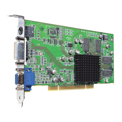
The 5420 VGA Card is a small, low power, video card that supports
a wide variety of CRT and flat panel displays for high performance
applications. The 5420 has 512K of video memory and 1 MB of
VRAM for frame buffering when using simultaneous displays, or
for accelerated performance when using one display.
The 5420 interfaces easily with standard VGA monitors with
analog inputs using a DB–15 connector. Flat panel displays are
connected to the 5420 using a 50–position IDC connector.
MAJOR FEATURESMAJOR FEATURES
MAJOR FEATURES
• Fully VGA, EGA, CGA, MDA and Hercules compatible
• Supports analog CRT monitors, interlaced and non–interlaced,
up to 800 x 600 x 256 colors, or 1024 x 768 x 16 colors
• Supports monochrome LCD, EL and plasma flat panels up to
1280 x 1024 with 67 gray scales
• Supports TFT LCD panels with 185,193 color palette
• Supports single drive and dual drive color STN LCD panels
with 226,981 color palette
• Drives CRT and flat panel displays simultaneously
• Adjustable Vee Bias supply for LCD panel
• 5V operation
• –40° to 70° C
HARDWARE INSTALLATIONHARDWARE INSTALLATION
HARDWARE INSTALLATION
The 5420 SVGA Video Card requires one slot in a Micro PC card
cage. Any slot in the card cage will work. The card plugs directly
into the backplane.
Octagon assumes no responsibility for any damage
caused to flat panel displays and/or Micro PC
video cards if the display is connected incorrectly.
WARNING:
5420 Super VGA Video Card – 1

Equipment
You will need the following equipment (or equivalent):
• 5420 SVGA Video Card and utility disk
• Octagon PC Control Card
• Micro PC Card Cage
• Power Module
• IBM compatible monitor w/cable or flat panel display w/cable
• PC SmartLINK
• Your PC
To install the 5420:
1. Please refer to Figure 1 for the location of various connectors
and option jumpers before installing the 5420.
(
c
)
Figure 1—5420 Component Diagram
5420 Super VGA Video Card – 2

The 5420 SVGA Video Card contains static–
sensitive CMOS components. The card is most
susceptible to damage when it is plugged into a card
cage. The 5420 card becomes charged by the user,
and the static discharges to the backplane from the
pin closest to the card connector. If that pin
happens to be an input pin, even TTL inputs may be
damaged. To avoid damaging your card and its
components:
1. Ground yourself before handling the 5420 card.
2. Disconnect power before removing or inserting
the card.
Take care to correctly position the 5420 card in the
card cage. The Vcc and ground signals must match
those on the backplane. Figure 2 shows the relative
position of the 5420 card as it is installed in the
card cage.
A31 B31 Card Edge Pins
A31 & B31
Card Edge Pins
A1 & B1
Micro-PC
Motherboard
A1 B1
5420 SVGA
Card
Figure 2—Edge Connector Orientation
2. The 5420 is factory configured and programmed for a VGA
analog monitor and a 640 x 480 STN color dual drive LCD flat
panel. Make sure the W2 BIOS enable jumper is in the enable
position, W2[1–2]. If you are using a different monitor or flat
panel display, you must reprogram the video BIOS for the
appropriate display. See “Programming the 5420 Video BIOS.”
WARNING:
5420 Super VGA Video Card – 3

3. Slide the 5420 into the Octagon card cage. The components on
the card should face to the left or upward depending on the
type of card cage.
4. Power on your system.
5. Refer to Figure 3 for a functional diagram of the 5420 card:
PC Bus
65530 SVGA
Controller
82C404
Clock
Decode
29C256
Ext
BIOS
DC-DC
Converter
50-position IDC
J1
DB-15
J2
Y1
14-318
MHz
R6 DC
Adj
Flat Panel Data
Analog VGA
Data
Address
Display
Memory
Filter
W2 W4
DC Polarity
See, page 9
W3
Figure 3—5420 Functional Diagram
5420 Super VGA Video Card – 4

PROGRAMMING THE 5420 VIDEO BIOSPROGRAMMING THE 5420 VIDEO BIOS
PROGRAMMING THE 5420 VIDEO BIOS
The 5420 is factory configured and programmed to support a
standard VGA monitor and a 640 x 480 STN color dual drive LCD
flat panel. If you are using the default monitor and/or flat panel
video BIOS, skip to the “Connecting the Monitor/Display” section.
If you are using a monitor/display other than the default settings,
please read the following instructions. Programming the 5420
requires a serial communications link between your PC and the
Octagon Control Card.
Micro PC Control Systems
• If you are installing your Micro PCControl Card for the first
time, follow the instructions in the Control Card user’s
manual for using a video card and continue with the steps in
the section “To program the 5420”.
or
• If you have already installed the Control Card to boot from a
flash EPROM or static RAM, reconfigure your Control Card to
boot from the BIOS drive (refer to your user’s manual).
Establish a serial communications link between your PC and
Control Card with COM1 as the main console. Continue with
the steps in “To program the 5420”.
To Program the 5420
NOTE: The following instructions assume you are using the 5420
in a Micro PC system.
1. Power off the 5420.
2. Make sure W4[3–4] is installed.
BIOS Video Write Enable: W4
Pins Jumpered Description
[1-2]* On* = use 32K BIOS;
Off = use 64K BIOS
[3-4]* BIOS Write Enable
* = default
3. Set jumper W2[2–3] on the 5420. This disables the 5420 and
allows you to use the serial port on your Control Card for
terminal emulation.
5420 Super VGA Video Card – 5

BIOS Enable/Disable: W2
Pins Jumpered Description
[1-2]* Enables the video BIOS
[2-3] Disables the video BIOS
* = default
4. Start PC SmartLINK on your desktop PC.
5. Power on the Micro PC system. The Control Card logon
message should display on your PC monitor.
6. Download the file, PGMVIDEO.EXE, and the *.DAT file for
your display (e.g. EL640.DAT) to your Control Card. Refer to
your Control Card user’s manual for detailed information on
downloading files to the Control Card using the TRANSFER
program.
NOTE: For previous users, the PGM5420.EXE has been
enhanced and renamed to PGMVIDEO.EXE.
NOTE: If you are using a flat panel display, refer to the
README.DOC file on the 5420 Utility Disk for a list of the
supported displays. Refer also to Octagon's web site,
www.octagonsystems.com, for the latest listing of supported
flat panels. If your particular display is not currently listed,
please contact Technical Support for assistance. The direct
line to Technical Support is 303–426–4521 and the
7. Change the W2 jumper to W2[1–2]. This enables the 5420
BIOS.
NOTE: Do not power off the 5420 when changing the jumper
setting at W2.
8. To program the 5420 for the appropriate monitor/display, type
the following:
<drive>:PGMVIDEO <drive>:Flatpanel.DAT
NOTE: “Flat panel” is the generic name. To obtain the correct
flat panel name specific to your model, refer to your 5420
Utility Diskette.
5420 Super VGA Video Card – 6

The <drive> designator is the RAMDISK where you trans-
ferred the files from your PC. The *.DAT file will change
depending on the type of display you are using. The following
message will be displayed:
VIDEO BIOS programming utility
------------------------------------------------------
PGMVIDEO Vers. x.xx Copyright (c) Octagon Systems Corp
------------------------------------------------------
You must reboot after running this program.
Make sure the jumper labeled EN-DIS is at the EN
position.
Do you want to continue? (Y/[N])
9. Enter 'Y' when asked if you want to proceed. The program
PGMVIDEO then updates the video BIOS on the 5420. The
system displays the following message:
Programming ... Please wait ...
Verifying ... Please wait ...
PGMVIDEO completed.
If verification errors occur, confirm that the CPU shadowing is
disabled for the C000-C800 memory range; then retry pro-
gramming.
10. Power off the 5420 and connect your monitor/display.
NOTE: Removing W4[3–4] disables the video BIOS write enable.
This prevents unintentional programming of the video BIOS.
INVERTED SHIFT CLOCK: W4INVERTED SHIFT CLOCK: W4
INVERTED SHIFT CLOCK: W4
The 5420 provides a shift clock signal for flat panels. For some
panels, such as EL (electroluminescent), which may require the
shift clock to be inverted, W4[9-10] can be moved to W4[7-8].
Shift Clock: W4
Pins Jumpered Description
[7-8] Inverted Shift Clock
[9-10]* Shift Clock
* = default
5420 Super VGA Video Card – 7

CONNECTING THE MONITOR/DISPLAYCONNECTING THE MONITOR/DISPLAY
CONNECTING THE MONITOR/DISPLAY
The 5420 supports both a CRT monitor and a flat panel display.
The programs CT.COM and FP.COM allow you to toggle between
displaying the monitor and the flat panel. The program SM.COM
allows you to display from the monitor and the flat panel simulta-
neously. However, this option is video BIOS/flat panel dependent
and may not work with every flat panel. These programs are
found on the 5420 Utility Disk along with other diagnostic and
configuration utilities.
Analog Monitor
1. The DB–15 connector at J2 supports an analog VGA color or
monochrome monitor. Plug the cable supplied with your
monitor directly into J2.
Analog Connector: J2
Pin# Function
1Red
2 Green
3Blue
4NC
5 Digital Gnd
6AnalogGnd
7AnalogGnd
8AnalogGnd
9+5Vsafe
10 Digital Gnd
11 NC
12 NC
13 HSync
14 V Sync
15 NC
2. Make sure the video BIOS jumper is enabled — W2[1–2].
3. Configure and program your Micro PC Control Card for use
with a video card and monitor. Refer to your Control Card’s
manual.
4. Boot your Micro PC system.
5420 Super VGA Video Card – 8

5. A BIOS and DOS message similar to the following should
appear on your video monitor:
Octagon 50xx BIOS vers x.xx
Copyright (c) 1992-1995, Octagon Systems Corp.
All Right Reserved.
Flat Panel Display
Some panels require a BIAS voltage for contrast control. This
voltage is available on J1, pins 24 and 25. Refer to the data sheet
that comes with your flat panel. Steps 1, 2, 3, and 8 only apply to
panels that require a BIAS voltage.
1. Configure jumper block W3 for the polarity of the voltage
required and voltage positive/negative select:
BIAS Polarity
Pins Jumpered Description
W1[1-2] Vee +/- to J1, pins 22 & 23; pins 24 &25
W3[1-2]* Positive DC output to J1,pins 24 & 25
W3[2-4] Negative DC output to J1, pins 24 & 25
* = default
2. Verify that W3(7-8) is installed.
Range Adjustment Select: W3
Pins Jumpered Description
7-8 Adjustable ± 12 to± 31
No jumper Disable bias Vee adjustability
* = default
3. Power on the 5420 and measure Vee at J1, pin 24 and adjust
R6 to the correct voltage for your display. Refer to the “Pro-
gramming the 5420 Video BIOS” section.
To avoid damage to your panel, initially set the
voltage low and adjust to the specifications of your
panel.
5420 Super VGA Video Card – 9
WARNING:

NOTE: Without a flat panel BIOS programmed into the
EEPROM and W2[1-2] installed, Vee will not come up.
4. Power off the 5420 and connect the flat panel display to the
5420 using a 50–position IDC connector.
Improperly attaching a flat panel to the 5420
SVGA card could damage the Chips & Technolo-
gies video chip. The problem is due to flat panels
having connector pins that are not clearly marked
and assumptions are made as to the location of
pin 1. For example, Sharp LM32008F and other
Sharp Quarter VGA panels have this problem.
The silk-screen for CN1 on these panels is placed
next pin 12. This causes the user to assume that
pin 12 is pin 1 and as a result, the panel is wired
backwards. This in turn causes damage to the
video chip.
Carefully read the flat panel documentation and
diagrams, which clearly identify the placement of
pin 1, so that damage to the 5420 can be avoided.
Octagon assumes no responsibility for any
damage caused to flat panel displays and/or Micro
PC video cards if the display is connected
incorrectly.
CN1
This is PIN 1
Figure 4—LM32008F Quarter VGA Panel
WARNING:
5420 Super VGA Video Card – 10
WARNING:

The following table lists the pin number and function for the
flat panel connector at J1:
Flat Panel Connector: J1
Pin # Function Pin # Function
1ACDCLK 2 Gnd
3FLM 4 Gnd
5LP 6 Gnd
7BLANK* 8 Gnd
9SHFCLK 10 Gnd
11 ENAVDD* 12 Gnd
13 PNL0 14 Gnd
15 PNL1 16 Gnd
17 PNL2 18 Gnd
19 PNL3 20 Vdd (+5V)
21 Vdd (+5V) 22 Vee2
23 Vee2 24 Vee, +/-BIAS
25 Vee, +/-BIAS 26 PNL4
27 Gnd 28 PNL5
29 Gnd 30 PNL6
31 Gnd 32 PNL7
33 Gnd 34 PNL8
35 Gnd 36 PNL9
37 Gnd 38 PNL10
39 Gnd 40 PNL11
41 Gnd 42 PNL12
43 Gnd 44 PNL13
45 P8 46 PNL14
47 P9 48 PNL15
49 P10 50 P11
* = active low
NOTE: Several of these pins are multifunctional
and change depending on the BIOS loaded. Refer
to the README file on the 5420 Utility Disk for
more information.
5420 Super VGA Video Card – 11

5. Make sure the BIOS jumper is enabled — W2[1–2].
6. Power on your Micro PC System.
7. A BIOS and DOS message similar to the following should
appear on your display:
Octagon 50xx BIOS vers x.xx
Copyright (c) 1992-1995, Octagon Systems Corp.
All Rights Reserved.
8. Due to loading of the Vee source, the Vee voltage will probably
require additional adjustments at this time in order to obtain
proper contrast. With the power on, remeasure Vee at J1
pin 24 and adjust R6 for the correct voltage.
USING THE 5420 IN A DESKTOP PC WITH A FLAT PANELUSING THE 5420 IN A DESKTOP PC WITH A FLAT PANEL
USING THE 5420 IN A DESKTOP PC WITH A FLAT PANEL
Programming the 5420 video BIOS while in a desktop PC is
possible to do, but certain cautions must be heeded. Memory
manager software, such as HIMEM.SYS, QEMM, and 386MAX, for
example, must NOT be running, and any memory shadowing, as
well as CPU cache, must be disabled. If these situations exist
while programming the video BIOS, the video BIOS will become
corrupted and the desktop system will lock up with NO way to
reprogram the 5420 without using an Octagon Micro PC Control
Card.
To program a 5420 video BIOS in a desktop PC:
1. Disable all memory shadowing and CPU cache in the desktop
PC configuration setup.
2. Power off and disable the video in the desktop PC. Install the
5420 SVGA card and attach the PC monitor to the 5420 DB-15
connector.
3. Boot the desktop PC with a SYSed DOS diskette without a
CONFIG.SYS or AUTOEXEC.BAT file. This diskette will also
need the file PGMVIDEO.EXE and the .DAT file to be pro-
grammed into the 5420 card.
5420 Super VGA Video Card – 12

4. To program the 5420 for the appropriate flat panel display,
type the following:
A:PGMVIDEO <file>.DAT
The .DAT file will change depending on the type of display you
are using. The following message will be displayed:
VIDEO BIOS programming utility
------------------------------------------------------
PGMVIDEO Vers. x.xx Copyright (c) Octagon Systems Corp
------------------------------------------------------
You must reboot after running this program.
Make sure the jumper labeled EN-DIS is at the EN
position.
Do you want to continue? (Y/[N])
5. Enter 'Y' when asked if you want to proceed. The program
PGMVIDEO then updates the video BIOS on the 5420. The
system displays the following message:
Programming ... Please wait ...
Verifying ... Please wait ...
PGMVIDEO completed.
If verification errors occur, confirm that the CPU shadowing is
disabled for the C000-C800 memory range and that CPU
caching is disabled as well; then retry programming.
6. Power off the CPU, connect the flat panel display and power
on the desktop PC again.
EMI NOISE REDUCTIONEMI NOISE REDUCTION
EMI NOISE REDUCTION
If EMI noise generation becomes a consideration, EMI noise can be
reduced by grounding the metal VGA connector to chassis ground
by using braided wire and wire lugs.
5420 Super VGA Video Card – 13
Table of contents
Other Octagon Video Card manuals