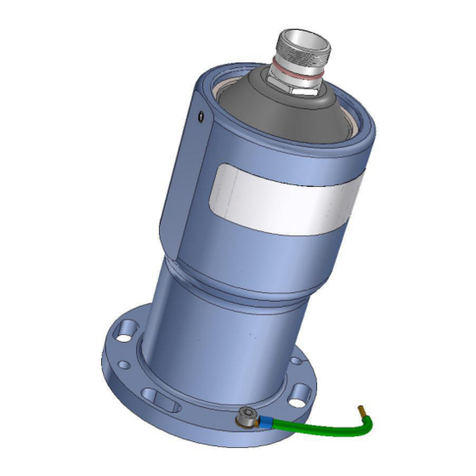
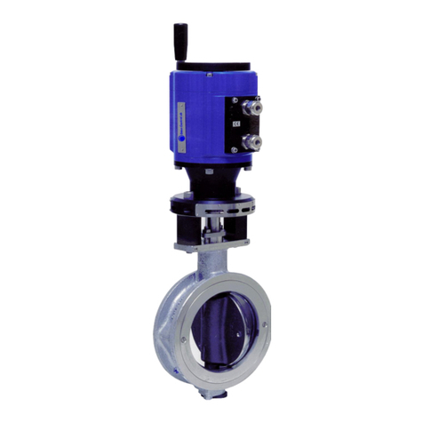
Oden Control P30R1 User manual

Version GR 2003-10-26
ODEN
® ELECTRIC ACTUATORS
P30R1 P30R2 P30H P30L1 P30L2
USER´SGUIDE
INSTALLATION AND MAINTENANCE MANUAL

Version GR 2003-10-26
DOWNLOAD FROM: WWW.ODENCONTROL.SE
PAGE 2
CONTENTS
1.0 General information
1.1 The Oden®family
1.2 Operation and safety instructions
2.0 Technical description
2.1 P30 Basic Unit
2.2.1 Turning module 30R1
2.2.2 Turning module 30R2
2.3.1 Linear module 30L1
2.3.2 Linear module 30L2
2.4 High torque module 30H
2.51 Cable A
2.52 Cable B
2.61 Connection board A
2.62 Connection board B
2.63 Connection board C
2.7 High temperature version—W
3.0 Mechanical installation
3.1 Acceptance control
3.2 Tools
3.3 Installation
4. Electric connections
5. The calibration system PC/PC
5.1 Power Calibration
5.1.1 Automatic Power Calibration
5.1.2 Manual Power Calibration
5.2 Position Calibration
5.3 Summing up of the PC / PC - Calibration System
6. Maintenance and service
7. Trouble shooting
Drawings and product data See www.odencontrol.se

Version GR 2003-10-26
COPYRIGHT ODEN CONTROL AB (PUBL) PAGE 3
1. GENERAL INFORMATION
1.1 The Oden®family
The Oden®family of Electric Actuators are
made specifically for the process industry.
The family consists of rotary, linear and
on/off actuators designed for the most de-
manding environment in the industry.
The following four models are basic units,
which can be combined with several types
of modules producing actuators meeting
different demands.
• P30 Basic Unit with 30 Nm max. control
torque
• P50 Basic Unit with 50 Nm max. control
torque
• P220 Basic Unit with 190 Nm max.
control torque
• P500 Basic Unit with 400 Nm max.
control torque
These units can be combined with either
rotary modules:
• 30R1 - 30R2
• 50R - 220R - 500R
• 30H (Type A 1,500 Nm and Type B
2,000 Nm max. control torque resp.)
or linear modules:
• 30L1 with 12 kN max control force
• 30L2 for valves with threaded spindle
• 50L with 12 kN max control force
• 220L with 50 kN max control force
• 500L with 100 kN max control force
The rotary actuators are 900actuators, but
can also be used as multi turns actuators
with a maximum working range of 160 turns
(57.600 degrees) at the output shaft.
All the Oden®Electric Actuators are pro-
grammable by the OVP (Oden®Valve Pro-
gram) software – Ref. Appendix for the OVP
Manual.
The Oden®Electric Actuator is pre-
programmed with default data, unless set by
the customer prior to shipment. We kindly
ask our customers to use the Internet and
the Customer Data Input on:
www:odencontrol.se for easy access.
Later, the User can modify his input data
(and any default data). Just connect a com-
puter (laptop) to the RS 232-interface and
make the necessary changes — Ref. The
OVP Manual.
Always check for latest versions of the
manuals at Oden’s web site
www:odencontrol.se .
1.2 Operation and safety
— instructions -
The actuator must only be used for controlling valves
and similar applications. Incorrect use may cause dan-
ger. Hence, functions and safety of the actuator can-
not be guaranteed.
Authorised personnel only must carry out the me-
chanical and electrical installation. Unauthorised per-
sonnel must be kept out of the working area.
Local regulations concerning technical equipment
must be observed when installing and/or maintaining
the actuator. Necessary steps to prevent any accidents
must be taken.
This manual deals with:
P30R1, P30R2, P30H ,P30L1 and
P30L2 models
2. TECHNICAL DESCRIPTION

Version GR 2003-10-26
Type Basic Unit Module Cable Connection
Board
Remarks
P30R1 P30 30R1 A = 10 m
B = 25 m
A, B or C Max. 160 turns,
Spindle adapter type
30R1
P30R2 P30 30R2 A = 10 m
B = 25 m
A, B or C Max. 160 turns,
Spindle adapter type
30R2
P30L1 P30 30L1 A = 10 m
B = 25 m
A, B or C Linear actuator,
Standard stroke 40 mm
P30H P30 30H+30R2 A = 10 m
B = 25 m
A, B or C High torque
Max. angle 900
P30L2 P30 30L2 A = 10 m
B = 25 m
A, B or C Linear actuator,
Max. stroke 20 mm
D
OWNLOAD
FROM
:
WWW
.
ODENCONTROL
.
SE
PAGE 4
2.1 P30 Basic Unit
The unit consists of a sealed aluminium housing
which includes a brushless servomotor, a reduc-
tion gearbox, electronics and a connector
24 V DC feeds the servo system.
The control signal is normally the standard 4-20
mA , adigital signal or a field bus communication.
The electronics with all the power and logical
components are placed inside the unit, close to
the motor. A connector is fitted and grounded to
the rear end of the unit.
All parameters as torque, speed, working range
are programmed by a special software — the
OVP (Oden®Valve Program) Software (See App.
B).
NB
The parameter settings in the software are saved
in a permanent memory and cannot be lost even
during an extended power break.
The current position will be automatically saved in
a permanent memory during a power break. If the
valve has changed its position, the electronics will
detect the motion (if the break is less than 8 hrs).
After more than 8 hours power break an auto-
matic Power Calibration will be performed, as
soon as the power has returned (this function can
be disabled in the software).
To make sure that the valve is sealing tightly in
closed position, an automatic new Power Calibra-
tion will be performed every time the valve
reaches the closed position.
To avoid that a jamming of the valve occurs in
closed position depending on thermal expan-
sions, an automatic calibration will occur every 20
minutes. (This function can be disabled in the
software).
See also 5. The Calibration system PC/PC.
No batteries or potentiometers, limit switches
or other sensitive electro-mechanical compo-
nents are used.
If the valve is blocked and cannot reach its posi-
tion, Oden®P30 will make 10 starting efforts. The
Actuator will then stop, and a mA-error signal is
sent as return signal. (The level of the signal can
be set in the software).
Another 10 starting efforts can be performed by
changing the control signal more than 2.5 mA.
This starting sequence prevents the actuator
making several attempts for an extended time
and thus damaging the valve or the actuator itself.
Temperature sensors protect the motor and the
electronics.
The reduction gearbox is based on the patent
protected Oden®principle and has a reduction
ratio of 63:1.
2.2.1 Turning module 30R1
This module is normally used for a 900valve
movement but can also be used as a multi turn
actuator with max. 160 turns.
This module (see drawing) consists of:
Shaft unit
The shaft unit should be fitted to P30 Basic Unit
with the two M5 screws.
The Oden®P30 should be fitted by four M8
screws to the valve flange adapter. (Not included
in this module)
(A common valve flange adapter design is a bent
steel plate with its outer surface provided with
four holes for the M8 screws and nuts)
The shaft, going throw the flange plate with a little
clearance , has a bow gear coupling at one end
and two slots with different width at the other end.
Also a radial sealing is included.
Slitted cage
The slitted cage is made in different versions with
internal diameters fitting normal valve spindles.
Clamp collar
The clamp collar has two M10 stop screws which
create clamping forces to the valve spindle by the
shaft and the slitted cage. To this friction torque a
key can also be added. (See drawing).
.
At a power break a threaded pin can be put into
one of the two not used M10 threads in the clamp

Version GR 2003-10-26
COPYRIGHT ODEN CONTROL AB (PUBL) PAGE 5
collar, as a handle for controlling the valve manu-
ally.

Version GR 2003-10-26
D
OWNLOAD
FROM
:
WWW
.
ODENCONTROL
.
SE
PAGE 6
2.22 Turning module 30R2
This module is normally used for multi-turns appli-
cations. (Combined with the P30 Basic Unit it is
called P30R2).
This module (see drawing) consists of:
Shaft unit
This shaft unit is almost the same as the unit in
module 30R1, and has no clamp collar system
but a shaft with a hole with a keyway fitting the
valve spindle.
2.3.1 Linear module 30L1
This module has a max standard stroke of 40
mm. However, special application designs with
longer strokes can be offered on request. (See
drawing).
(Combined with the P30 Basic Unit it is called
P30L1).
This module consists of :
Ball screw unit
The unit has a surface which fits against the
flange at P30 Basic Unit. It has also two rods,
which will be fitted to the valve flange adapter.
Valve flange adapter
This flange should be made to fit the actual valve
flange.
Spindle adapter
The spindle adapter should be machined to the
proper hole/thread for the actual valve. The spin-
dle adapter is slitted in two clamping parts and
are also guiding the spindle along one of the rods.
2.3.2 Linear module 30L2
This module has a max stroke of 20 mm. . (See
drawing).
(Combined with the P30 Basic Unit it is called
P30L2).
This module is used for valves with threaded
valve spindles, i.e. when the valve spindle is
turned it is making an linear movement.
This module consists of :
Spindle adapter
The spindle adapter, looking like a gear wheel,
should be machined to the proper hole/thread for
the actual valve spindle. Secure it by drilling a ra-
dial hole for a cylindrical pin.
Plastic window
This plastic ring has two purposes, to be a axial
support for the plastic gear wheel in the actuator
and to make it possible to see the valve position.
Valve adapter unit
The adapter unit consists of two pillars and a
valve flange adapter. This flange should be made
to fit the actual valve flange.
2.4 High torque turning module 30H
This module consists of a ball-screw system act-
ing on an lever fitted to the valve spindle by a
coupling. The module is enclosed in a flush tight
housing (see drawing).
Max. control torque 2,000 Nm
2.51 Cable A
The length of the cable is 10 meters.
2.52 Cable B
The length of the cable is 30 meters.
There is a connector in one end of the cable. The
cable has 9 different coloured conductors. The
shield in the cable must be grounded.
2.61 Connection board A
The connection board A is used for analogue con-
trol and is placed in a plastic box which fits to a
standard DIN-rack system in a protecting switch
cabinet.
The connecting board has 9 screw terminals with
the cable conductors colour text as follows:
2.62 Connection board B
The connection board B is used for digital control.
(Contact Oden Control for separate instructions).

Version GR 2003-10-26
Red Power + 24 V DC
Black Power - 0 V DC
White Control IN +
Brown Control IN -
Green Position OUT +
Yellow Position OUT -
Grey Computer TD/RS 232
Blue Computer RD/RS 232
Violet Computer GND/RS 232
COPYRIGHT ODEN CONTROL AB (PUBL) PAGE 7
2.63 Connection board C
The connection board C is used for on/off control.
(Contact Oden Control for separate instructions).
2.7 High temperature version — W
Oden® Basic Unit can also be delivered as a high
temperature actuator. This Basic Unit is called
P30W.
The surrounding temperature range is increased
(-400C — +900C).
The internal electronic boards are placed in a
separate tight box, which is connected to the P30
Basic Unit by a shielded cable (with a connector).
Max. cable length is 30 meters.
——————————————-
3. Mechanical installation
The examples in this chapter should be re-
garded as a guidance only. Actual installa-
tions may vary depending on the type of valve
used. Some adapter consoles and screws
might differ from those described below.
NB. The manufacturer’s warranty will
be void, if the cover including the con-
nector is dismantled.
NB. If the 24 V DC is connected during
the assembly or function control, the
valve might move.
3.1 Acceptance control
Please, check that the shipment is complete and
in accordance to the order:
• Delivery certificate
• P30 Basic Unit
• Alternative modules:
a. 30R1
b. 30R2
c. 30H + 30R2
d. 30L1
e. 30L2
• Cable with connector
• Connection board with DIN-rack box
• This manual
• OVP (Oden®Valve Program) Software
• Computer cable (RS232-computer connec-
tor)
• Valve flange adapter for actual valve (may
be enclosed in the delivery on request as an
option)
3.2 Tools
For an easy installation, the following tools are
necessary:
• Insex key (M8)
• Insex key (M5)
• Spanner for M8-nuts
• Blade screwdriver, width 2.5 mm
• Loctite, blue
3.3 Installation
P30R1:
Fit the valve flange adapter to the valve. Put the
valve spindle to closed position. (Some valve
spindles are changing their axial position in
closed position).
The 30R1 turning module should be fitted to the
P30 Basic Unit by the two M5 screws. Use Loctite
in the threads.
Put the slitted cage in place on the valve spindle
(the cage should be matched to the actual spindle
diameter).
Put P30 Basic Unit in place using the four M8 with

Version GR 2003-10-26
D
OWNLOAD
FROM
:
WWW
.
ODENCONTROL
.
SE
PAGE 8
washers and Loctite.
The axial play between the locking ring and the
flange plate of the 30R1 should be 1 mm (+/- 0.8
mm).
Add Loctite at the threads of the two M10 stop
screws at the clamp collar and tight them firmly.
Check that the valve/actuator is running smoothly
by adding a threaded pin to the M10 thread in the
clamp collar and then rotate the valve.
P30R2:
Machine the spindle adapter to a close fitting to
the valve spindle shaft and its key.
Then make the installation in accordance to the
instruction for P30R1 above.
P30L1:
Check that the spindle adapter has the same
thread as the valve spindle. Put the flange
adapter to the valve flange.
Put the linear module 30L1 with its rods to the
flange adapter.
Put the valve spindle in max. opened position.
Fit the valve spindle to the ball-screw by the spin-
dle adapter.
Check by rotating the gear coupling in the P30L1
that it runs smoothly, and there is a small play
between the spindle adapter and the rod.
NB Check that the working range is within the
working range of the P30L1.
Put P30 Basic Unit to the P30L1 by the four
screws M8 x70 and washers.
In a dirty or corrosive environment use a rub-
ber bellow to protect the free surface of the
ball-screw. (May be enclosed to the delivery)
P30L2:
The spindle adapter, looking like a gear wheel,
should be machined to the proper hole/thread for
the actual valve spindle. Secure it by drilling a ra-
dial hole for a cylindrical pin.
Fit the valve adapter unit to the valve.
(The adapter unit consists of two pillars and a
valve flange adapter. This flange should be made
to fit the actual valve flange)
Put the plastic ring in place.
(This ring has two purposes, to be a axial support
for the plastic gear wheel in the actuator and to
make it possible to see the valve position)
Turn the valve spindle in max. opened position.
NB Check that the working range is within the
working range of the P30L2.
Put P30 Basic Unit to the 30L2 by the two M8
screws and washers.
P30H: High Torque model
(For installation, please consult the appropriate
drawings).
There is a DIN-standard concerning valve moun-
ting flanges. Many valve manufacturers still have
their own internal standards, and Oden Control
has designed adapters to the most common
valves on the market.
It is not necessary to use shims to aligne the
Oden® Actuator to the valve.
For other types of actuators this alignment proc-
ess is difficult, and you can easily get an uncon-
trolled load to the valve spindle bushings and the
gland sealing. Hence, the Oden®Actuators im-
prove significantly the lifetime of the valve itself.
4. ELECTRIC CONNECTIONS
Place the connection board with the DIN-rack box
in your cabinet.
Connect the cable conductors to the connection
board in accordance to the colour text markings.
(See 2.61 Connection board A alt. 2.62 Connec-
tion board B alt. 2.63 Connection board C).
Connect the cable shield to ground.
Check once more that the voltage is 24 V DC,
and that the conductors are correctly connected
to the terminals.

Version GR 2003-10-26
COPYRIGHT ODEN CONTROL AB (PUBL) PAGE 9
5. THE CALIBRATION SYSTEM
- PC/PC
The electronic calibration system will automati-
cally find the closed valve position.
The calibration system PC/PC means Power Cali-
bration/Position Calibration.
There are different kinds of calibration system de-
pending on actual application.
5.1 Power Calibrations
5.1.1 Automatic Power Calibration
An automatic calibration will be carried out when
the 24 V DC is powered on. After that the valve
will go to the position the control signal repre-
sents.
The calibration will last about 5 seconds. The
maximum opening angle, starting from this closed
position, is either set by default value, by Cus-
tomer Data Input or from the setting in the OVP
software.
The Power Calibration will be carried out with 50
% of the programmed control torque.
An automatic Power Calibration is carried out
every time the valve reaches its closed position. If
the valve remains in closed position, this se-
quence will be repeated every 20 minutes.
The reason for this routine is to be certain that the
valve is tight in closed position without the risk of
being jammed. Jamming might occur depending
on a change in the ambient temperature distri-
bution (thermal expansion forces in the valve).
The automatic 20-minutes calibration will avoid
such occurrence.
The electronics will remember the calibration po-
sition at a power break.
During 8 hours power break all valve movements
will be detected.
After more than 8 hours power break a new auto-
matic calibration (Power Calibration) will be car-
ried out automatically to correct for any spindle
movement.
This automatic function as well as the 20-minutes
calibration routine can be disabled in the software
5.1.2 Manual Power Calibration
If you for some reason want to make a new cali-
bration within 8 hours after a power break,
please do as follows:
1. Short-circuit the pins TD and RD at the RS
232-connector.
2. Then, put the power 24 V DC on. Oden®
Actuator will now make a calibration. (It will
last for some seconds). When ready the
Oden®Actuator is moving to the control
signal position.
3. Remove the short-circuit of TD and RD.
Similar to Automatic Power Calibration, the maxi-
mum opening angle, starting from this position, is
set by either default, Customer Data Input or from
the OVP software.
A manual Power Calibration can also be done
from the OVP.
5.2 Position Calibration
If the valve has no mechanical stop (as a ball
valve normally does not have) or if the valve is
too sensitive for the calibration torque/force (for
example the valve will jam at closed position), but
yet you require the programmed control
torque/force, then we recommend using Position
Calibration.
You are manually setting the calibration position
and the max. opened position with the Position
Calibration
Please do as follows:
NB No computer connection to the RS232
connector.
1. Move the valve manually to closed position.
2. Remove any connections to terminal num-
ber 3 and 5 at the terminal cover. Short-
circuit terminal number 3 and 5.
3. Then, put the 24 V DC power on.
4. Oden®Actuator will remember this position

Version GR 2003-10-26
D
OWNLOAD
FROM
:
WWW
.
ODENCONTROL
.
SE
PAGE 10
as the calibration position and starts open-
ing the valve.
5. When the valve has reached the requested
max. opened angle position, quickly remove
the terminal short-circuit.
6. Oden® will immediately stop and remember
this position as the max. opened angle
value.
7. Connect the control and position signal con-
ductors (terminal 3 – 5).
The calibration values are stored in a permanent
memory in the electronics.
No automatic new calibration will be done after >8
hours power failure. Hence, Oden® will not react
on the control signal until a new Position Calibra-
tion (or a Power Calibration) is carried out.
No automatic calibration or 20-minutes calibration
will occur in closed position.
It is possible to make adjustments of the working
range in the OVP software after a Position Cali-
bration.
5.3 Summing up of the
PC / PC – calibration system
The position value will never be lost even dur-
ing a long period of a power break.
The position value will be automatically saved to
a permanent memory at a power break.
During 8 hours power break all valve movements
will be detected.
Using Power Calibration:
After more than 8 hours power break a new auto-
matic calibration (Power Calibration) will be car-
ried out automatically to correct for any spindle
movement.
Using Position Calibration:
After more than 8 hours power break a new cali-
bration had to be carried out manually to correct
for any spindle movement.
The automatic Power Calibration after >8 hours
power failure is possible to disable in the OVP
software.
6.0 Maintenance
Control and preventive maintenance should be
carried out only in every three years. In case of
heavy loads of the Actuator (and the valve) the
intervals should be shorter.
The Oden® Actuator gears and the bearings are
lifetime greased and need no service.
Control points:
Calibration control:
Make a new PC/PC -calibration (see instructions
above).
Positioning control:
Position the valve near the middle of the working
range. Increase the control signal very slowly until
the valve spindle starts to move. Read the mA-
value. Decrease the control signal very slowly un-
til the valve spindle starts to move in the other
direction. Read the mA-value. The signal differ-
ence is a measure of the backlash of the system
(positioning accuracy).
To indicate the motion of the valve spindle,
fix an indicator pin to it.
A common cause for backlash is that the spindle
adapter is not properly fixed to the valve spindle.
Compare the motion to a indicator pin at the spin-
dle adapter.
NB Most of the backlash is normally eliminated by
the media in the pipe system when it is forcing the
valve spindle.
Hence, this test should be made during a normal
pressurised system.
Electronic contact control:
Control and clean the surfaces in the terminal
blocks at the connection board.
Torque control:
With OVP software it is possible to control the
condition of the valve. By slowly increasing the
control torque until Oden® starts to move you can
notice a change in valve bearing condition.
NB This test must be done with the gland nuts
slightly released, because these will affect the
torque.

Version GR 2003-10-26
These controls can be written down in the
notepad when saving the OVP data file.
7. TROUBLE SHOOTING
7.1 Mechanical troubles
The interface between the actuator and the
valve can cause problems depending on
the lack of valve flange and spindle stan-
dards accepted by the valve manufacturer.
Oden® has designed many different adapt-
ers to the most common valve types. It is
important to check that the right adapters
are used. (See 3.3.Installation).
Check in the Order Confirmation that the
proper valve closing direction, torque,
speed and working range have been cho-
sen.
7.2 Control or calibration troubles
If the actuator is not possible to control or
calibrate, please make the following test:
Please, check your 24 V DC.
Please, check your control signal.
The reason for the blocking may be a too
hard preloading of the valve gland sealing,
bad valve bushings, corroded valve spin-
dle, some type of interference or that the
necessary torque is higher than the chosen
control torque in the OVP software.
The electronics in P30 is protected by tem-
perature sensors. If P30 is blocked it will
continuously deliver the highest torque it is
programmed to. The temperature will then
increase until it reach about 70 degrees
(default setting) surrounding temperature.
At this temperature it breaks the torque and
the temperature starts to decrease until I
reaches 60 degrees (default settings).
Then the control power automatically starts
up again.
During the cooling period the position will
be kept even if there is an outer torque.
Connect the computer to RS232 and check
that the right parameters have been cho-
sen in the OVP Software .
Carry out a new Power Calibration (refer to
the OVP Manual for further instructions).
If you still have problems, please contact
your Oden®representative
————————————————-
COPYRIGHT ODEN CONTROL AB (PUBL) PAGE 11

Version GR 2003-10-26
D
OWNLOAD
FROM
:
WWW
.
ODENCONTROL
.
SE
PAGE 12
Oden P30R2

Version GR 2003-10-26
D
OWNLOAD
FROM
:
WWW
.
ODENCONTROL
.
SE
PAGE 13
Oden Control AB (publ.)
Nilstorpsvägen 53
181 47 LIDINGÖ
Sweden
Phone: (+46) 08 767 76 57
Fax: (+46) 08 767 47 18
E-mail: sales@odencontrol.se
Patent protected in all major countries.
US patent 5,913,744
Copyright
Oden Control AB (publ.)
This manual suits for next models
4
Table of contents
Other Oden Control Controllers manuals
Popular Controllers manuals by other brands

CLIVET
CLIVET ELFOControl2 Installation, configuration and use manual

Spirax Sarco
Spirax Sarco 600 Series Installation and maintenance instructions

Siemens
Siemens OZS164 series installation instructions

Honeywell
Honeywell VK41 R Series instruction sheet

EUROSTER
EUROSTER 11WB user manual

Danfoss
Danfoss AMV 410 installation guide

NatComm
NatComm DS2 user guide

Ingersoll-Rand
Ingersoll-Rand 150BMG Series Installation and maintenance information

Intersil
Intersil ISL6446ADEMO1Z user guide

Power integrations
Power integrations InnoSwitch 3-Pro Toggle Board user guide

Malmbergs
Malmbergs PJA003 instruction manual

Fortinet
Fortinet FortiADC 400F quick start guide