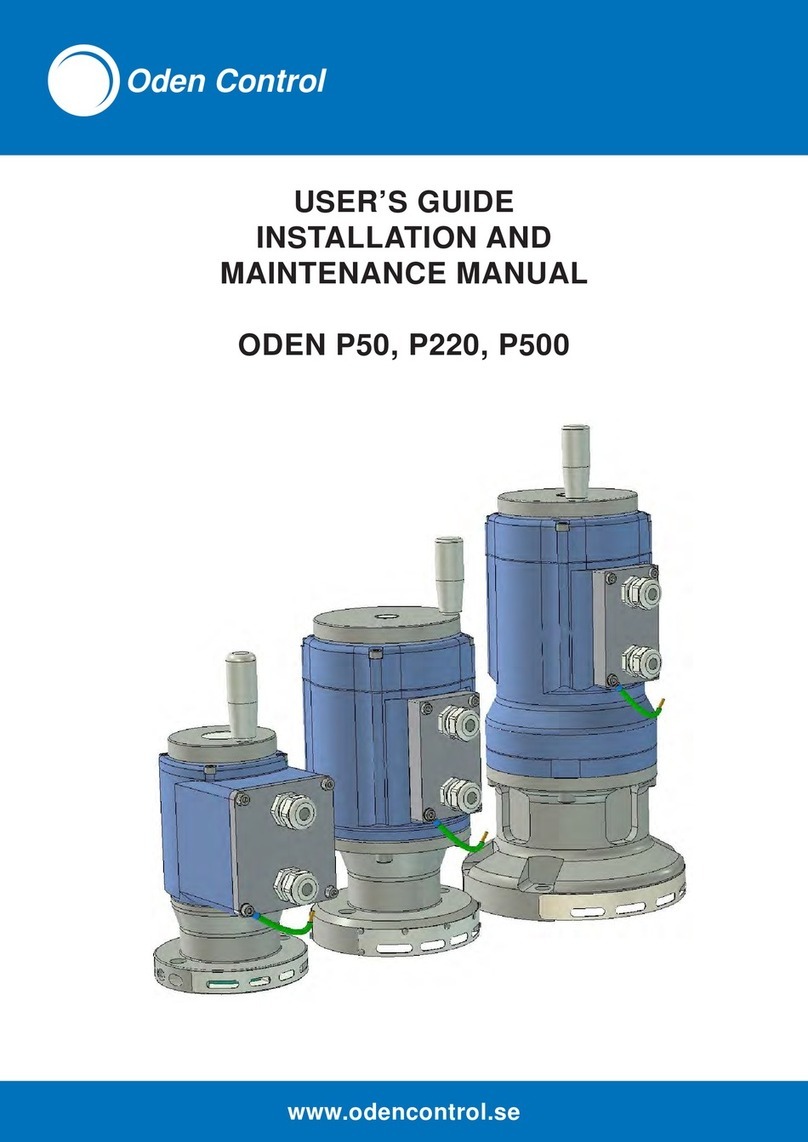
Oden Control P50R Manual

Version GR 2003-10-26
ODEN
® ELECTRIC ACTUATORS
P50R P220R And P500R
USER´SGUIDE
INSTALLATION AND MAINTENANCE MANUAL
Oden P50R
Copyright
Oden Control AB (publ.)

2
Content:
1.0 General information
1.1 The
Oden®family
1.2 Operation and safety instructions
2.0 Technical description
2.1 Basic Unit
2.2 Spindle Adapter
2.3 Adapter consoles and screws
2.4.1 Connection board A
2.4.2 Connection board B
2.4.3 Connection board C
2.5 High temperature version—W
3.0 Mechanical installation
3.1 Acceptance control
3.2 Tools
3.3 Installation
3.3.1 Installation of the spindle adapter
3.3.2 Installation of the actuator
3.3.3 Mechanical control
4. Electric connections and installation
5. The calibration system PC/PC
5.1 Power Calibration
5.1.1 Automatic Power Calibration
5.1.2 Manual Power Calibration
5.2 Position Calibration
6. Maintenance and service
7. Trouble shooting
Drawings and Performance data see ==> www.odencontrol.se

3
Version GR 2003-10-26
1. GENERAL INFORMATION
1.1 The Oden®family
The Oden®family of Electric Actuators are
made specifically for the process industry.
The family consists of rotary, linear and
on/off actuators designed for the most
demanding environment in the industry.
This manual deals with the Oden® rotary
positioning actuator group, which consists of
four basic units:
• P30R with a maximum control torque
of 30 Nm
• P50R with a maximum control torque
of 50 Nm.
• P220R with a maximum control torque
of 190 Nm.
• P500R with a maximum control torque
of 400 Nm.
The P30 is a high speed positioner, which is
mainly used as a fast rotary actuator, but
also as a linear actuator. One of the models
in the P30 family is the P30H—a high
torque actuator with 2,000 Nm maximum
control torque.
(See separate manual concerning the P30
family of Actuators).
The P50R, P220R and P500R range are
900actuators. but can also be used as multi
turns actuators with a maximum working
range of 160 turns (57.6000) at the output
shaft.
When working with a range larger than 900
the two indicator pins - which also are used
as mechanical stops - should be replaced
by two stainless stop screws.
All the Oden®Electric Actuators are
programmable by the OVP (Oden®Valve
Program) software – (Ref. Appendix for the
OVP Manual).
The Oden®Electric Actuator is pre-
programmed with default data, unless set by
the customer prior to shipment. We kindly
ask our customers to use the Internet and
the Customer Data Input on:
www:odencontrol.se for easy access.
Later, the User can modify his input data
(and any default data). Just connect a
computer (laptop) to the RS 232-interface
and make the necessary changes — Ref.
The OVP Manual in the Appendix.
Always check for new versions of the
manuals on the Internet using the Oden
Control AB homepage. The latest – updated
– versions are always available to download
on the Internet. Look for the version number
on the right down corner on the front page!
1.2 Operation and safety
— instructions -
The actuator must only be used for controlling valves
and similar applications. Incorrect use may cause
danger. Hence, functions and safety of the actuator
cannot be guaranteed.
Authorised personnel only must carry out the
mechanical and electrical installation. Unauthorised
personnel must be kept out of the working area.
Local regulations concerning technical equipment
must be observed when installing and/or maintaining
the actuator. Necessary steps to prevent any accidents
must be taken.
This manual deals with:
P50R, P220R and
P500R models
2. TECHNICAL DESCRIPTION

4
The Oden®actuator consists of :
2.1 Basic Unit
The unit consists of a sealed aluminium
housing with a step-motor, a reduction gear-
box, electronics and terminal blocks.
At the top of the unit there is a hand wheel,
actuated by pulling it out. On the wheel there
is a warning sign: “Excessive torque may
damage either the valve or the actuator”.
The step-motor is fed by 24 V DC.
The control signal is normally the standard
signal 4 - 20 mA, a digital signal or a field bus
communication. (The most actual drawings
can be downloaded from:
www.odencontrol.se).
The electronics, with all the power and logical
components, is inside the unit, close to the
motor.
The power and control signal cables are
connected through the cable inlets to the
terminal blocks inside a removable terminal lid
at the side of the housing. These cables are
not supplied, and we kindly ask our customers
to use one (with a minimum of 9 different
conductors) or two shielded cables
All parameter values as torque, speed,
working range are set in a special software —
the OVP (Oden®Valve Program) Software -
Ref. Appendix.
The current position will be automatically
saved in a permanent memory during a power
break. Even if the hand wheel is used during
this time, the actuator remembers the original
calibration value (if the failure is < 8 hrs).
After more than 8 hours power break an
automatic calibration is performed, when the
24 volts returns (this function can be disabled
in the OVP). (See also 5. The Calibration
system PC/PC).
No potentiometer or battery are used to
remember this position value, nor limit
switches or other sensitive electro-mecha-
nical components.
The reduction gearbox is based on the patent
protected Oden®principle and has a reduction
ratio of 100:1.
2.2 Spindle adapter
The adapter has to be machined to fit to the
actual valve spindle. Normally it should have a
round hole with a key groove, but also square
or splined holes are common. All depends on
the type of valve spindle.
The unit has two indicating pins also serving
as mechanical stops.
A steel plate resting on the adapter consoles
will protect from finger damage.
2.3 Adapter consoles and screws
The adapter consoles will have different sha-
pes depending on which type of valve Oden®
will be adapted to.
For the types P50 and P220, the most
common adapter consoles are just two long
M12 screws going throw the flange of the
Actuator and throw two round bars with holes.
The screws are fitted to the threads in the
valve flange.
(See 3D-drawings of P50 with modules which
show the design principle).
Available options:
2.4 Connection boards
There are 4 types of connection boards:
• Connection board A1 is used for
analogue control signals (default unit)

5
Version GR 2003-10-26
• Connection board A2, similar to A1,
but has potentional free control and
position signal terminals.
• Connection board B is used for digital
control signal.
• Connection board C is used for on/off
control.
2.6 High temperature version—W
A high temperature version (-400C — +900C)
is also available. This Basic Unit is called
P50W/P220W or P500W.
The internal electronic is protected in a
separate tight box, which is connected to the
Basic Unit by a shielded cable. The cable has
a length of 25 meters and is included.
3. MECHANICAL INSTALLATION
The examples in this chapter are just a
guidance and may vary depending on the
different types of valves. Some adapter
consoles and screws can differ from those
described below.
NB The manufacturers warranty will be
void if the top cover (with the hand wheel)
is dismantled.
NB If the 24 V DC is connected during
assembling or function control, the valve
may move.
NB The valve spindle moves in the
opposite direction to the hand-wheel.
3.1 Acceptance control
Please check that the delivery is complete
according to the delivery documents (and that
it is adapted to the correct valve, if applicable).
• Delivery certificate
• Basic Unit—P50, P220 or P500
• Spindle adapter
• (Cable—only W-versions)
• This manual
• OVP (Oden®Valve Program)
• Computer cable (RS232-computer
connector)
3.2 Tools
For the mechanical installation, the following
tools are necessary:
P50R:
Spanner, 24 mm (cable inlets)
Hexagon key, M5 (terminal lid)
Hexagon key, M10 and M12
Blade screwdriver, width ca. 2.5 mm
Loctite blue
Hexagon key , for valve flange screws
P220R and P500R:
Spanner, 24 mm (cable inlets)
Hexagon key, M5 (terminal lid)
Hexagon key, M12
Blade screwdriver, width ca. 2.5 mm
Loctite blue
Hexagon key , for valve flange screws
3.3 Installation
3.3.1 Installation of the spindle adapter
The spindle adapter consists of a gear wheel,
which is the inner part of a gear coupling and
two indicator pins (firmly fitted and locked by
Loctite) which are used both as coarse visual
valve position indicators and as mechanical
stops.
A protection plate is placed on the adapter
consoles to eliminate the risk for finger clamp
injuries.
Machine the spindle adapter (together with the
pins) to a close fitting to the valve spindle
shaft and its key.

6
Clean the top surface of the spindle adapter,
put some Loctite to the inside edge and place
the washer with the convex surface turned up.
With a strike from a hammer or with a hand
press the washer should be deformed and
seal the fitting.
NB. The washer must be mounted in accor-
dance to this instruction to meet IP67
regulations (Warranty condition).
Put the adapter consoles to the valve flange.
Move the valve to closed position. (Some val-
ve shafts change the axial position in the
closed valve position). Put the protection plate
at the adapter consoles.
Use a hand press or a similar tool to push the
spindle adapter in position. The indicator pins
should now be in 450to the valve.
A max and A min are max/min permitted
length of the valve spindle above the upper
surfaces of the adapter consoles.
It is important that the spindle adapter has
the right axial position. The bottom surface
of the spindle adapter should have the
same position as the top surface of the
protection plate, when positioned on the
adapter console. The tolerance should be 0
- +1.5 mm (above the protection plate
surface).
It is important having a tight fitting to the
spindle and its key in order to benefit of the
high accuracy of the Actuator.
Do not use a hammer, this can damage the
valve spindle.
3.3.2 Installation of the actuator
The drawings show one type of adapter
consoles, two cylindrical bars with holes.
Remove the protection tape around the gear
teeth of the spindle adapter and put some
grease at the gear from the enclosed plastic
bag.
Put the two long screws in the flange of the
Actuator, through the protection plate and the
bars.
Put the Actuator carefully in position by
slightly turning it in both directions to get the
gears in the spindle coupling in correct
position to each other. An air cushion effect
might prevent the mounting, but the air
disappears after a while.
Use the hand wheel smoothly to turn the
Actuator to the right position for the screws in
relation to the valve flange threads.
When the valve is closed, check that there is a
clearance of minimum 2 mm between the
indicator pins and the mechanical stops in the
Oden actuator. For ball valves with no
mechanical stops in the valve, the closed
position will of course be when the indicator
pins hit the mechanical stops in the actuator.
There are threads in the mechanical stops in
the actuator. If it is necessary stop screws
can be used as adjustable stops. It is
important that these stop screws will hit
the indicator pins at the same time. (one
stop pin cannot take the full load (it will be
destroyed) and a dangerous tilting load can
harm the reduction gear in the actuator.
There is a DIN-standard concerning valve
mounting flanges. But in spite of that many
valve manufacturers still have their own
standards, and Oden®has designed adapters
to the most common valves on the market.
3.3.3 Mechanical control
The hand-wheel is actuated by pulling it out.
It is not recommended using the hand-
wheel, when the power is on. However, it
A max A min
Oden P50R 52 mm 20 mm
Oden P220R 79 mm 30 mm
Oden P500R 114 mm 50 mm

7
Version GR 2003-10-26
will in any case not damage the actuator.
Notice the warning label on the hand-wheel.
Careless handling will damage the valve or
the actuator.
As an extra protection against overloading the
P50 can be delivered with a slipping coupling.
NB. The hand-wheel moves in the opposite
direction to the valve.
Please, check that the actuator can be
operated easily by hand within the whole
working range. The valve must be closing
completely. It should be running smoothly.
If not: loose the adapter screws and let the
unit centre itself, then alternately tighten the
screws. If the actuator is horizontal, relieve the
weight of the actuator manually during
alternately tightening of the screws.
The Oden®actuator must not be aligned to
the valve spindle by using shims.
For other types of actuators this alignment
process is difficult and you easily get an
uncontrolled loading to the valve spindle
bushings and the gland sealing, hence the
Oden®actuator significantly improves the
lifetime of the valve.
4. ELECTRIC CONNECTION
Remove the M5-screws on the terminal lid.
Disconnect the ribbon cable connector.
Put the shielded cables through the cable
inlets and connect the conductors to the
terminal block at the connection board. The
cable shield will then be connected to the
connector which is grounded.
Connect the ribbon cable connector.
Check once more that the voltage is 24 V DC,
and that the conductors are correctly
connected to the terminals.
NB. If only one cable inlets is used, the
other one must be plugged by the
enclosed rubber washer. (Warranty
condition)
5. THE CALIBRATION
SYSTEM - PC/PC
To calibrate the actuator/valve -system means
to find the closed valve position which
correspond to the closed position of the
control signal , normally 4 mA.
The calibration system PC/PC means Power
Calibration / Position Calibration.
Which type of the two calibration system you
will use depends on the actual application.
5.1 Power Calibrations
5.1.1 Automatic Power Calibration
An automatic calibration will be carried out
when the 24 V DC is powered on. After that
the valve will go to the position the control
signal represents.
The calibration will last about 5 seconds. The
maximum opening angle, starting from this
closed position, is either set by default value,
by Customer Data Input or from the setting in
the OVP software.
The Power Calibration will be carried out with
50 % of the programmed control torque
(default).
An automatic Power Calibration is carried out
every time the valve reaches its closed
position. If the valve remains in closed
position, this sequence will be repeated every
20 minutes.
The reason for this routine is to be certain that
the valve is tight in closed position without the
risk of being jammed. Jamming might occur
depending on a change in the ambient
temperature distribution (thermal expansion

8
forces in the valve). The automatic 20-minutes
calibration will avoid such occurrence.
The electronics will remember the calibration
position at a power break.
During 8 hours power break all valve
movements will be detected.
After more than 8 hours power break a new
calibration (Power Calibration) will be carried
out automatically to correct for any spindle
movement.
An automatic new calibration will be carried
out when reaching closed position and then
every 20 minutes if remaining in closed
position.
This automatic function as well as the 20-
minutes calibration routine can be disabled in
the software
5.1.2 Manual Power Calibration
If you for some reason want to make a new
calibration within 8 hours after a power break,
please do as follows:
1. Short-circuit the pins TD and RD at the
RS 232-connector.
2. Then, put the power 24 V DC on. Oden®
Actuator will now make a calibration. (It
will last for some seconds). When ready
the Oden®Actuator is moving to the
control signal position.
3. Remove the short-circuit of TD and RD.
Similar to Automatic Power Calibration, the
maximum opening angle, starting from this
position, is set by either default, Customer
Data Input or from the OVP software.
A manual Power Calibration can also be done
from the OVP.
5.2 Position Calibration
If the valve has no mechanical stop (as a ball
valve normally does not have) or if the valve is
too sensitive for the calibration torque/force
(for example the valve will jam at closed
position), but yet you require the programmed
control torque/force, then we recommend
using Position Calibration.
You are manually setting the calibration
position and the max. opened position with the
Position Calibration
Please do as follows:
NB No computer connection to the RS232
connector.
1. Move the valve manually to closed
position.
2. Remove any connections to terminal
number 3 and 5 at the terminal cover.
Short-circuit terminal number 3 and 5.
3. Then, put the 24 V DC power on.
4. Oden®Actuator will remember this
position as the calibration position and
starts opening the valve.
5. When the valve has reached the
requested max. opened angle position,
quickly remove the terminal short-circuit.
6. Oden® will immediately stop and
remember this position as the max.
opened angle value.
7. Connect the control and position signal
conductors (terminal 3 – 5) again.
The calibration values are stored in a per-
manent memory in the electronics.
No automatic new calibration will be done
after >8 hours power break. Hence, Oden®
will not react on the control signal until a new
Position Calibration (or a Power Calibration) is
carried out.
No automatic calibration or 20-minutes
calibration will occur in closed position.
It is possible to make adjustments of the
working range in the OVP software after a

9
Version GR 2003-10-26
Position Calibration.
5.3 Summing up of the
PC / PC – calibration system
Using Power Calibration:
During 8 hours power break all valve
movements will be detected.
After more than 8 hours power break a new
calibration (Power Calibration) will be carried
out automatically to correct for any spindle
movement.
An automatic new calibration will be carried
out when reaching closed position and then
every 20 minutes remaining in closed position.
(Can be disabled In OVP)
Using Position Calibration:
During 8 hours power break all valve
movements will be detected.
After more than 8 hours power break a new
calibration had to be carried out manually to
correct for any spindle movement.
Option:
A permanent memory saving function of the
position at a power break even in more than 8
hours. This is achieved by an electronic
hardware addition.
NB This function will not detect any
mechanical spindle movement after >8 hours.
6. MAINTENANCE
Control and preventive maintenance should
be carried out only in every three years. In
case of heavy loads of the Actuator (and the
valve) the intervals should be shorter.
The Oden® Actuator gears and the bearings
are lifetime greased and need no service.
Calibration control:
Make a new PC/PC-calibration (see instruc-
tions above).
Positioning control:
Position the valve near the middle of the
working range. Increase the control signal
very slowly until the valve spindle starts to
move. Read the mA-value. Decrease the
control signal very slowly until the valve
spindle starts to move in the other direction.
Read the mA-value. The signal difference is a
measure of the system backlash (positioning
accuracy).
To indicate the movement of the valve
spindle, connect a indicating pin to it.
A common cause for backlash is that the
spindle adapter is not properly fixed to the
valve spindle. For that reason compare the
movement of this pin with the indicator pins at
the spindle adapter.
NB Normally most of the backlash is
eliminated by the media pressure torque on
the valve spindle. The test should therefore be
made during a normal pressurised system.
Electronic contact control:
Control and clean the surfaces in the terminal
block.
Sealing control:
Control the surface of the inner surface of the
servo house. If it is dry and clean these will
indicate that the unit is properly sealed.
Torque control:
With the OVP Software it is possible to control
the condition of the valve by slowly increasing
the control torque until the Actuator starts
moving you can notice a change in valve
bearing condition.
NB. This test must be done with the gland
nuts slightly released, because these will
affect the torque.
The results of these controls can be written
down in the notepad in the saved OVP data
file.
7.TROUBLE SHOOTING
7.1 Mechanical troubles
The interface between the actuator and the

10
valve can cause problems depending on the
lack of valve flange and spindle standards
accepted by the valve manufacturer.
Oden®has designed many different adapters
to the most common valve types. It is impor-
tant to check that the right adapters are used.
(See 3.3. Installation).
Check in your order that the right valve closing
direction, torque, speed and working range
have been chosen.
7.2 Control or calibration troubles
If the actuator is not possible to control or
calibrate, please make the following test:
Remove the terminal lid. Inside the actuator
you can see two LED-indicators, one green
and one red.
If neither the green nor red LED are activated,
please check the 24 V DC power supply
If the red LED is activated, break the 24 V and
power on again. If you get red LED again,
break the 24 V, and contact your Oden®
representative.
If the green LED is activated, check that there
is a control signal.
If the green LED is activated and a control
signal of about 10 mA is sent and nothing
happens, please change the control signal
level to 7 mA and then 13 mA. If the Actuator
starts vibrating some seconds and then stops,
this indicates a blocked valve. The return
(position) signal has now changed to about 2
mA or 22 mA as an error indication.
The reason for the blocking may be a too hard
preloading of the valve gland sealing, bad
valve bushings, corroded valve spindle, some
type of interference or that the necessary
torque is higher than the chosen control
torque in the OVP Software
The Actuator will make about 10 starting
attempts, and then stops. To get another 10
attempts, change the control signal at least
2.5 mA.
This start algorithm prevents the Actuator
making starting attempts continuously during
a long time period, which may cause fatigue
damages to the valve or to the Actuator.
If the green LED is activated and the points 1
– 4 above are OK, but nothing happens,
connect the computer to the RS 232
connector, start the OVP Software and:
• check that the OVP Software is in
contact with the Actuator (red flashing
warning).
• check in the menu that the right type of
Actuator is chosen.
• open the sub menu and check the
parameter settings.
• calibrate by activating Power Calibration
(a warning pops up if the last calibration
was a Position Calibration).
• If nothing happens, check if the OVP
Software still has contact with the
Actuator (red flashing warning). If so
press the Default button for Default
settings. If the OVP Software has lost
contact with the Actuator (green flashing
warning), leave the program and then
recall the OVP Software
If you are not able to control the actuator and
get no contact with the OVP program, the
actuator may be in a not finished calibration
routine.
Please make a new manual calibration by
breaking the power, make a short circuit over
TD and RD at the connection board and then
power up.
If there still are problems, please contact Your
Oden®representative

11
Version GR 2003-10-26
Oden Control AB (publ.)
Nilstorpsvägen 53
181 47 LIDINGÖ
Sweden
Phone: (+46) 08 767 76 57
Fax: (+46) 08 767 47 18
E-mail: sales@odencontrol.se
Patent protected in all major countries.
US patent 5,913,744
This manual suits for next models
2
Table of contents
Other Oden Control Controllers manuals
Popular Controllers manuals by other brands

Schnick-Schnack-Systems
Schnick-Schnack-Systems Long Distance Controller user guide

adept technology
adept technology MV Instruction handbook

Unitronics
Unitronics Vision OPLC V130-33-TA24 installation guide

Xantech
Xantech MRKP2E installation instructions

Honeywell
Honeywell V7335A 2000 Series instruction sheet

Sentiotec
Sentiotec home.com4 Instructions for installation and use