B212 - ST1
1.
2.
3.
4.
5.
6.
7.
8.
9.
10.
11.
12.
13.
14.
15.
16.
17.
18.
19.
20.
B100 - ST3
1.
2.
3.
4.
5.
6.
7.
8.
9.
10.
Page 2 of 3
For Reference Only
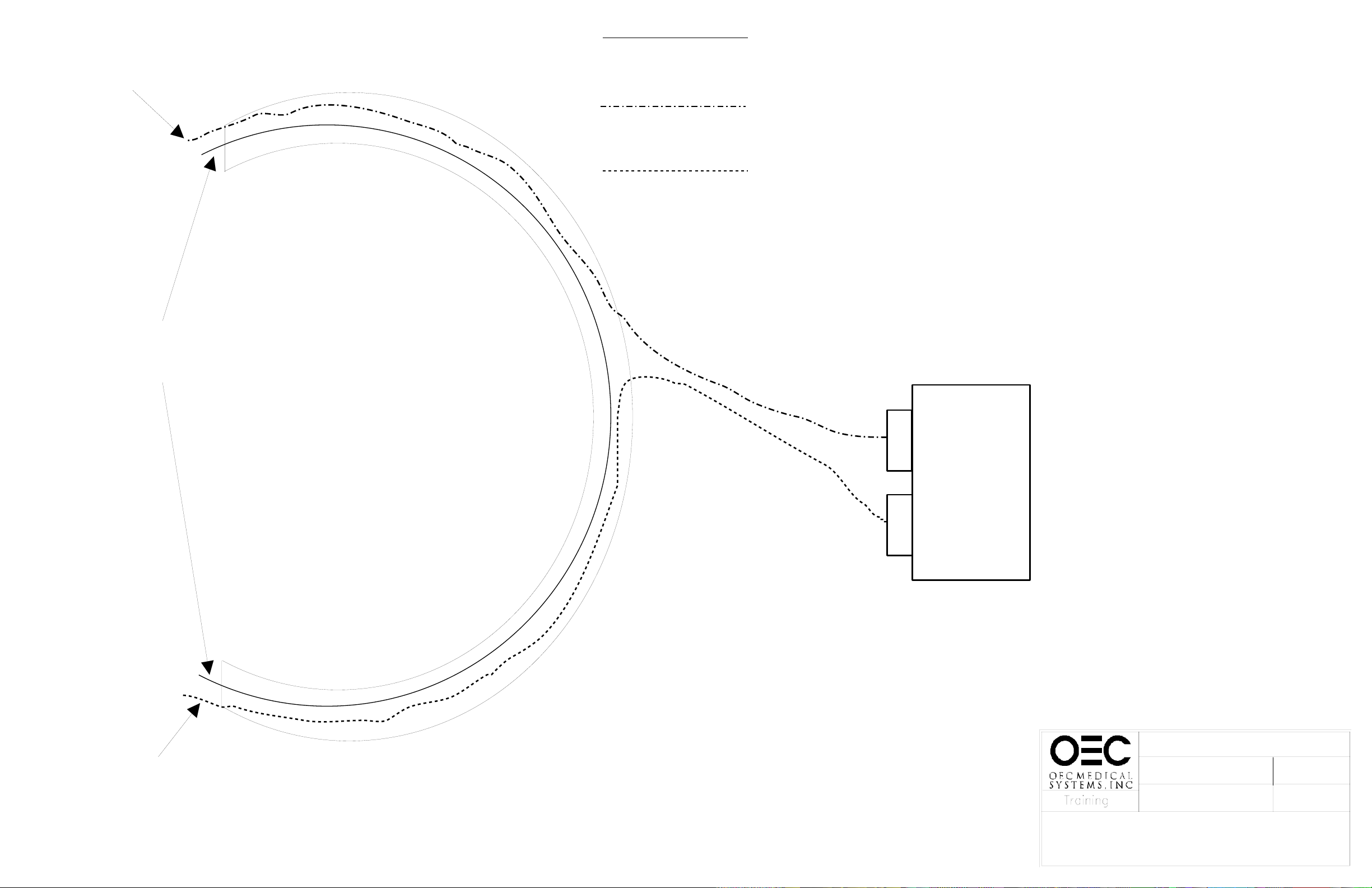
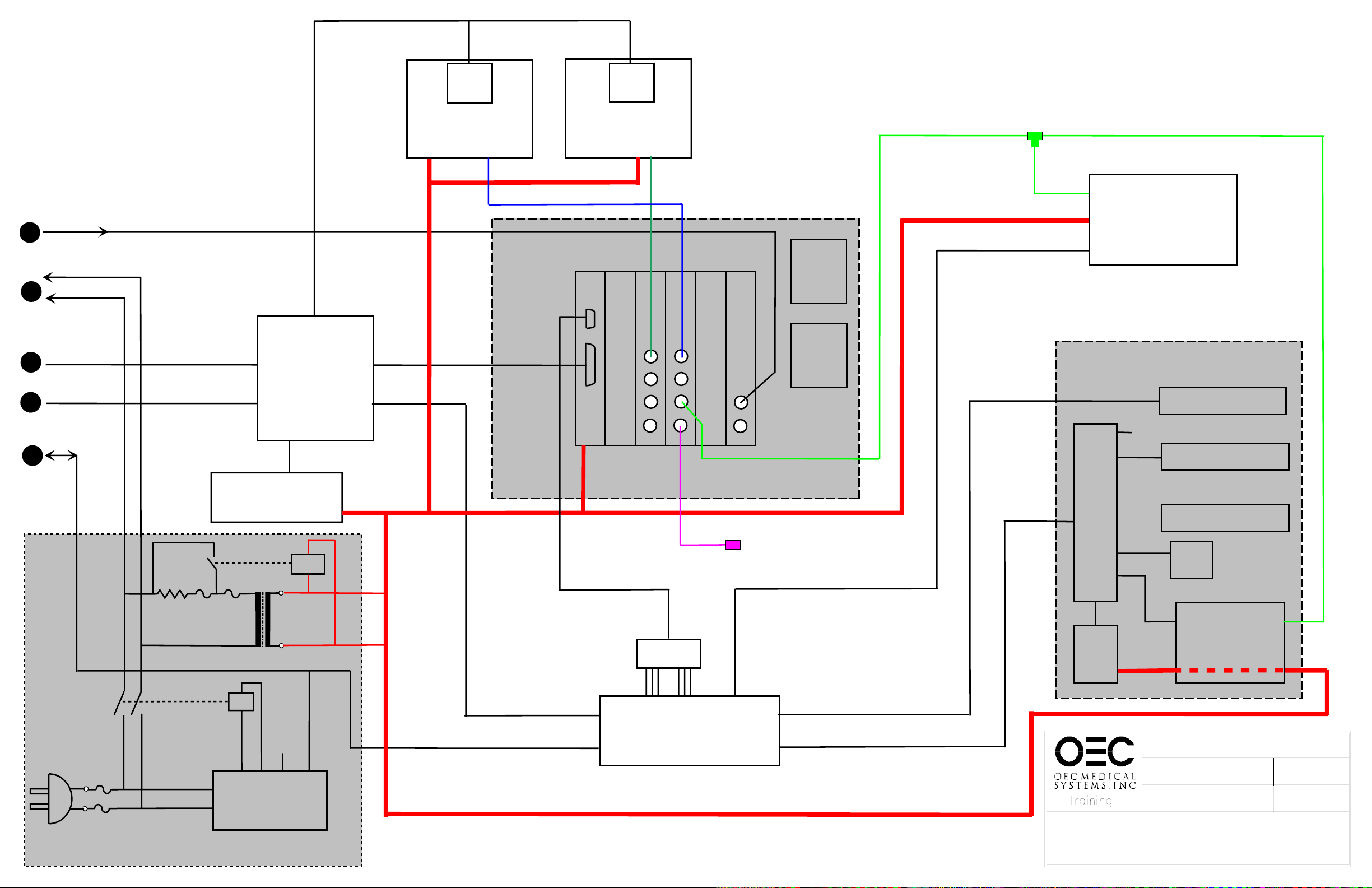
C-ARM CABLE
ROUTING/REPAIR
7/29/97C_CABLE.DS4
COMPACT / SERIES 7600
NOT USED, NO WIRES
WIRES AVAILABLE
FOR JUMPERING
20 PIN
CONNECTOR 10 PIN
CONNECTOR
-MAG*
DLIST
DA
-HAFDOS
The purpose of this procedure is to re-route an open signal line using available spare
wires in the cables already in the C-Arm. Read and understand the instructions before
performing this procedure.
1. Ohm out the ribbon cable in
question to isolate the problem signal.
2. If the broken wire is in the ribbon cable from the
B100 ST3 to the B212 ST1, use one of the spare
wires in that cable to replace the defective wire.
3. If the broken wire is in the ribbon cable from the
B100 ST4 to the Filter Board X3 you will need to use
one of the wires in the unused ribbon cable. Follow steps
4 through 9.
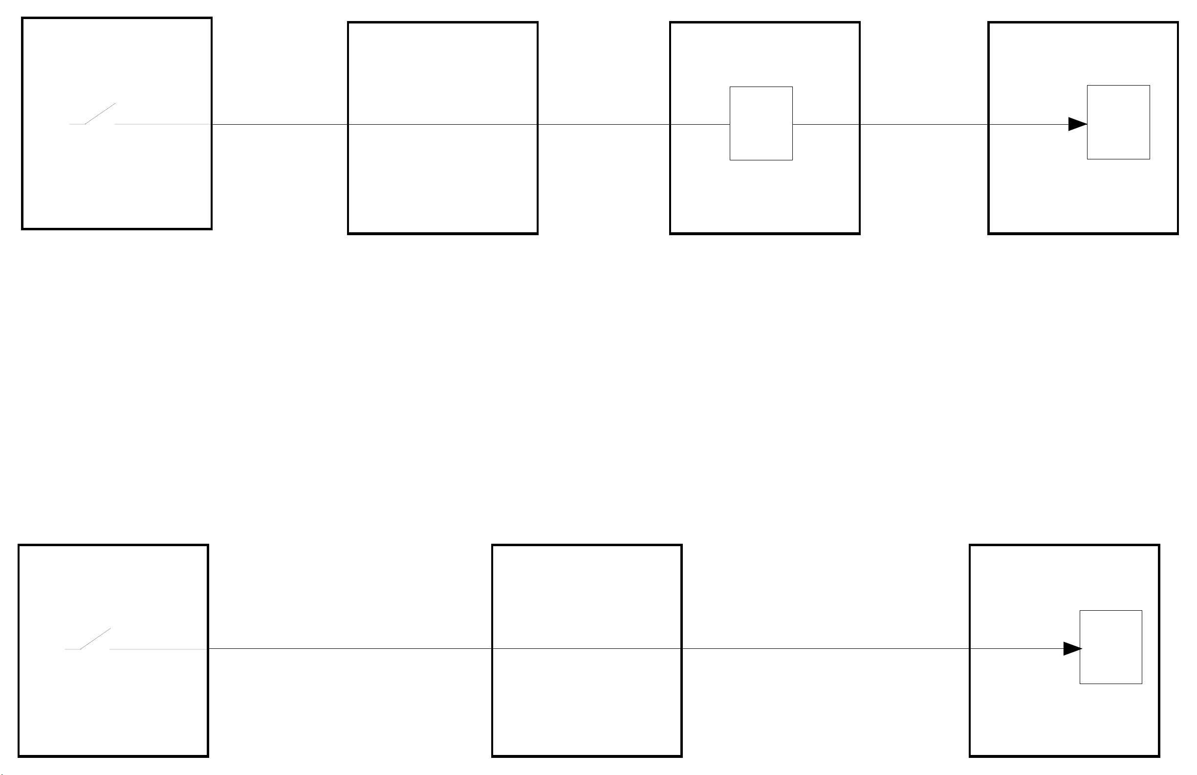
4. Disconnect the defective wire at X3 connection on the
Filter Board end of the cable and at the ST4 connection on
the B100 board end of the cable.
5. Carefully peel back one of the wires in the spare ribbon cable at the monoblock
end and install it in the X3 connector where the defective wire was removed (see A on sheet 3).
6. Carefully remove one of the spare wires (15-20) from the ST1 connector
on the B212 board.end of the ribbon cable between B212 ST1 and B100 ST3.(see B on sheet 3)
7. Connect the other end of the wire used in step 5 to the wire selected in step 6.
This connection should be soldered and covered with heat shrink tubing.
.
8. Disconnect the appropriate wire at the ST3 connector on the B100 board end and
install it into the empty location on the B100 ST4 connector of the cable. (see C on sheet 3).
9. Ohm out the new signal path to ensure a good connection..
Used and Refurbished C-Arms are Available from www.SharpMedical.com - Call us at 800-969-9800
An Independent C-Arm Service Provider. This PDF provided for research / historical purposes only.