OEL CTS-M20 User manual

M-20 Operation AndMaintenanceManual
83550-003-001 Revision C2008-01-03
1
Configuration:
(Usersettingsaresetto defaultsettings, unless otherwiseindicated below)
DefaultSetting UserSetting
J3 toLeftJ3 toRight
1Gas sensed Carbon Dioxide (CO2)
2Signal mode 2-10VLinear 4-20mA Linear
3Signal “CO2From” point 0ppm
4Signal “CO2To” point 2500 ppm
5Signal “SigFrom” at
“CO2From” point 2.0V 4.0mA
6Signal “SigTo” at
“CO2To” point 10.0V 20.0mA
7Output signal clipping Disabled
8Auto Zero No
9Altitude 300 feet
10
Password 0017
11
Relay Enabled
12
RelayOn1000ppm
13
RelayOff 950ppm
14
RelayOnDelay 0minutes
15
RelayOff Delay 0minutes
16
Global Average 360ppm
Specifications:
(Themanufacturerreservestheright to change theseatanytime)
Input Power(Nominal) 24 VACor24 VDC(Isolated)
Input PowerRange 18-40VACor18-40VDC
SensorType Non-DispersiveInfraRed (NDIR)
Thermo compensated aluminum block
EnclosureMaterials Polycarbonate/ABS blend,FireRetardant
Output Signal 0-20 mA,4-20mA,0-10Vor2-10 VorUserRange linear.
Temperature 5ºCto 40ºC
Humidity 0to 99%RH,non-condensing
Pressure Atmospheric±10%
SensorResponseTime Less than45 secondsfor90%of step change
Accuracy±2%of range
Repeatability ±10 ppm
Range Default0to 2500 ppm(4.0–20.0mA)
UserProgrammable0to 5000 ppm(0-10Vor0-20mA)
Display Alphanumeric2-lineX8-digitLCD
RelayOutput OneSinglePoleDoubleThrow(SPDT),FormC,1ampdrycontact
(CSA 1500 V,FCC Part68)
RelayTimeDelays Actuation –0to 60 minutesin5-minuteincrements.
De-actuation –0to 60 minutesin5-minuteincrements.
Mounting Screwmountsto astandard2” X4” electrical junction box.
Software Version 3.00 Revision A(orlater)

M-20 Operation AndMaintenanceManual
83550-003-001 Revision C2008-01-03
2
Special Features Signal output optionsinclude negativeslope.
Signal end-points:adjustableppm,0-10V,0-20mA.
Adjustablerelaydead-band.
Relaycanactivatefordecreasingppm.
Simulation mode to simulateanyppmvaluefrom 0to 5000.
Auto Zeroto global average over8-dayperiod.
Passwordprotection forusersettings.

M-20 Operation AndMaintenanceManual
83550-003-001 Revision C2008-01-03
3
TableofContents
1. INTRODUCTION......................................................................................4
1.1 Principleof Operation.............................................................................4
1.2 Display.................................................................................................5
1.3 Keypad.................................................................................................5
1.4 Output Signal........................................................................................5
1.5 SignalRange.........................................................................................5
1.6 Relay....................................................................................................7
1.7 Power...................................................................................................7
2. OPERATION............................................................................................8
3. FAULTINDICATION................................................................................8
4. CONFIGURATION....................................................................................9
4.1 User Interface.......................................................................................9
4.2 Menu Activation.....................................................................................9
4.3 Menu Item Selection............................................................................10
4.4 Menu Item Alteration...........................................................................10
4.5 Menu Tree...........................................................................................10
5. CALIBRATION.......................................................................................20
5.1 Equipment Required.............................................................................20
5.2 Gain Check..........................................................................................20
5.3 ZeroCalibration...................................................................................21
5.4 SpanCalibration..................................................................................21
6. TROUBLESHOOTING.............................................................................22
6.1 TroubleshootingTips............................................................................22
6.2 Fault Codes.........................................................................................24
7. DUCTMOUNT ADAPTER(CTS-M2000X-D00000)..................................25
8. WIRINGANDPOWERSUPPLY..............................................................26
WARRANTYSTATEMENT.............................................................................28
TableofFigures
Figure 1 -InternalViewandFeatures................................................................4
Figure 2 -SignalModeJumper (J3)....................................................................5
Figure 3 -DuctMount Configuration................................................................25
Figure 4 -DuctCutout....................................................................................25
Figure 5 -24VACFloatingSupply (4-Wire Installation)......................................26
Figure 6 -24 VACwith SeparateGrounds(4-Wire Installation)...........................26
Figure 7 -24VACwith CommonGrounds(3-Wire Installation)............................26
Figure 8 -24VDC Supply with CommonGround(3-Wire Installation)..................27
Figure 9 -24VDC Supply with SeparateGround(4-Wire Installation)..................27
Figure 10 -24VDC UngroundedSupply (4-Wire Installation)..............................27
Figure 11 -24VDC UngroundedSupply (3-Wire Installation)..............................27

M-20 Operation AndMaintenanceManual
83550-003-001 Revision C2008-01-03
4
1. Introduction
Thismanualappliesto M-20 unitswith softwareVersion 3.01 andlater(released 2008-01-
03).Ifyou haveaproductwith softwareVersion 1.XX,pleasecontactthefactoryto obtaina
copyof thecorrectmanual.
1.1 PrincipleofOperation
TheM-20 isamicroprocessorcontrolled CO2Sensor/Transmitterusinginfrared sensing
technology.Theconcentration ofCO2ismeasured bydeterminingtheamount ofabsorption
of light inaspecificfrequencyband.
An analogsignaloutput isprovided,as well as arelaywith adjustablesetpoints. New
featuresforVersion 3.01 softwareare;extension ofthesignaloutput range downto 0V(or
0mA)andaSimulation Mode to assistintestingtheinstallation beforecommissioning.The
fieldcalibration featuresof theunitareextended as well.
Theunitoperatesfrom nominal24VACor24VDCandincorporatesanisolated switching
powersupply.
Figure1 -Internal View andFeatures

M-20 Operation AndMaintenanceManual
83550-003-001 Revision C2008-01-03
5
1.2Display
Thedisplaymoduleisa2-lineby8-characterLCD.Thegas concentration displayformatin
measurement mode isas follows:
CO2ppm
XXXX
Wherexxxx isconcentration ofCO2,shownfrom -999 to 9999.Thedisplayed number
includesleadingzerosif below1000.Negativeconcentrationsindicatethattheunitrequires
calibration.Theconcentration isupdated every10 seconds.
NOTE: Thedisplayrange isnot thesameas theanalogoutput signalrange.Ifthe
signalrange issetto 2500 ppm,theconcentration will be displayed above
thesignalrange,eventhoughthesignalhas alreadystopped at20 mA or
10V.Theconcentration displayislinearupto 5000 ppm.Above5000ppm,
themeasurement becomesnon-linear.Thedisplayhas amaximum reading
of9999 ppm,inwhichcasetheactualconcentration maybe above
9999ppm.
1.3 Keypad
Thekeypadisasetofthree buttonsrecessed alongtheupperright side oftheenclosure.It
isnot necessaryto openthecoverforuse.Access to themenu systemispassword
protected.Press anykeyfor3secondsto enterthemenu system(see belowfordetails).
1.4 OutputSignal
Optionsfortheanalogoutput signalare:4-20 mA linear(default)or2-10Vlinear.Theoutput
mode canbe chosenmovingtheJ3jumper.Foroverrange concentrationsthesignalcan
exceed therange slightly(above20mA or10V)if clippingisdisabled (see belowfordetails).
Jumper3(J3)islocated inthetop-right handcornerof thecircuitcard.
1.5 Signal Range
Signalrange assignmentsallowtheuserto choosehowtheanalogoutput signaliscalculated
from thegas concentration.Thisallowsdirectoperation of louversandfanspeeds.
Thedefaultsettingsare0ppmCO2=4.0mA and2500 ppmCO2=20.0mA,with linearsignal
betweenthetwopoints. Thesesettingswill cover90%ormoreofapplicationsforindoorair
qualitycontrol.
Theusermayassignanygas concentration between0and5000 ppmto eachrange point in
stepsof50 ppm.Thelowerconcentration point iscalled the“CO2From”point andtheupper
concentration point iscalled the“CO2 To”point.Thesoftwarewill limittheminimum range
(differencebetweenthetwopoints)to 500ppm.
NOTE: The“CO2To” point cannot be setsmallerthanthe“CO2From” point.
Figure2 -Signal ModeJumper(J3)

M-20 Operation AndMaintenanceManual
83550-003-001 Revision C2008-01-03
6
ThecorrespondingVoltage orCurrent pointscanbe adjusted between0Vand10V(for
voltage output mode)or0mA to 20mA (forcurrent output mode).
Thecurrent (orVoltage)pointscanbe setto anyrelation,meaningthe“SigFrom”point and
“SigTo”point canbe swapped to obtainanoutput responsewith anegativeslope.Fora
negativeslope theoutput Voltage (orcurrent)will decreaseas theconcentration increases.
NOTE: Alwayssetthe“JumperJ3”settingto matchJ3on theunit.It isadvisableto
maintainatleast4Vor(8mA)betweenthetwo“Sig”points. Thesoftware
doesnot performcheckingon thesesettings. Whileinthemenu system,or
beforethefirstmeasurement,thesignal issetto “SigFrom”.
When“Clipping”isenabled,thesignaloutput will not gobeyondeitherofthetwocurrent (or
Voltage)end-points. When“Clipping”isdisabled,thesignaloutput will goto 0Vor0mA
minimum to about 10.75V(21.5mA)maximum.
Signal OutputOptions
“JumperJ3”
Setting “Clipping”
Setting Jumper
J3 AnalogOutput
SignalRange
“LeftVDC” “Disable”
0.0V – 10.75V
(default)
“LeftVDC” “Enable”
“SigFrom”– “Sig
To”
in Volt
“RightMA” “Disable”
0.0mA – 21.5mA
“RightMA” “Enable”
“SigFrom”– “Sig
To”
in mA
Signal SettingExamples
Example Settings Jumper
J3 AnalogOutput
Signal Range
500-1500ppm
2.5V–8.5V
“JumperJ3” =“LeftVDC”
“CO2From” =“0500ppm”
“CO2To” =“1500ppm”
“SigFrom” =“02.50V”
“SigTo” =“08.50V”
“Clipping” =“Disable”
0.0V–10.75V
500-1500ppm
2.5V–8.5V
“JumperJ3” =“LeftVDC”
“CO2From” =“0500ppm”
“CO2To” =“1500ppm”
“SigFrom” =“02.50V”
“SigTo” =“08.50V”
“Clipping” =“Enable”
2.5V–8.5V
0-2500ppm
1.0V–5.0V
“JumperJ3” =“LeftVDC”
“CO2From” =“0000ppm”
“CO2To” =“2500ppm”
“SigFrom” =“01.00V”
“SigTo” =“05.00V”
“Clipping” =“Disable”
1.0V–10.0V

M-20 Operation AndMaintenanceManual
83550-003-001 Revision C2008-01-03
7
Example Settings Jumper
J3 AnalogOutput
Signal Range
0-2500ppm
1.0V–5.0V
“JumperJ3” =“LeftVDC”
“CO2From” =“0000ppm”
“CO2To” =“2500ppm”
“SigFrom” =“01.00V”
“SigTo” =“05.00V”
“Clipping” =“Enable”
1.0V–5.0V
0-2500ppm
4.0mA –20.0mA
(default)
“JumperJ3” =“RightMA”
“CO2From” =“0000ppm”
“CO2To” =“2500ppm”
“SigFrom” =“04.00mA”
“SigTo” =“20.00mA”
“Clipping” =“Disable”
4.0mA –21.5mA
0-2500ppm
4.0mA –20.0mA
(defaultwith clipping
enabled byuser)
“JumperJ3” =“RightMA”
“CO2From” =“0000ppm”
“CO2To” =“2500ppm”
“SigFrom” =“04.00mA”
“SigTo” =“20.00mA”
“Clipping” =“Enable”
4.0mA –20.0mA
0-5000ppm
0.0mA –20.0mA
“JumperJ3” =“RightMA”
“CO2From” =“0000ppm”
“CO2To” =“5000ppm”
“SigFrom” =“00.00mA”
“SigTo” =“20.00mA”
“Clipping” =“Enable”
0.0mA –20.0mA
IMPORTANT: TheSignalRange istheapplied range of theanalogoutput signal.The
DisplayRange isindependent ofthesignalrange andisdefined from
0ppmto 5000 ppm.It isnon-linearabove5000 ppmto amaximum of
9999ppm.Negativeconcentrationsmaybe shown,but indicatethat
theunitneedscalibration.Theglobalaverage forCO2isintheorder
of360ppmandshouldbe thelowestconcentration measured under
mostconditions.
1.6Relay
Onesinglepoledoublethrow(SPDT;FormC,Drycontacts)with 1Ampereratingisstandard.
Configuration allowsadjustment foractuation point,deadband,anddelays. Therelay
settingshavethesamerange as thedisplay(0-5000ppm),andareindependent ofthe
analogoutput signal range.
NOTE: Therelaysetpointsmaybe setto operateon declininggas concentrations
simplybysettingthede-actuation setpoint (“RelayOff”)to agreater
concentration thantheactuation setpoint (“RelayOn”).
1.7 Power
TheM-20 canbe powered from anACorDCpowersourcewith nominalvoltage of24V.The
powersupplyisisolated andthereforefewrestrictionsexistinthenumberofwiring
configurations.
NOTE: Thepowerinput isisolated from theinternalpoweroftheunit,but the
analogsignaloutput isnot isolated from theinternalpoweroftheunit.For
installationswhereisolation isrequired forthesignal,thepowersupply
isolation will be sufficient.Theuserneedsto bearinmindthattheanalog
output signalisreferenced to thesecondaryside oftheisolated power
supply.

M-20 Operation AndMaintenanceManual
83550-003-001 Revision C2008-01-03
8
2. Operation
Whentheunitispowered up,itdisplaysasoftwarerevision string,followed bythegas
identification stringas shownbelow:
Thedisplayshowsthesoftwarerevision for3seconds:
QEL M-20
V3.01 RA
Where“V3.01” indicatesthesoftwareVersion and“RA” thesoftwareRevision number.
Therevision stringisfollowed by:
CO2ppm
----
Where“----” indicatethatthefirstmeasurement isinprocess.
After10 seconds, thebottom displaylinewill showtheconcentration ofCO2inppm.The
measurement isupdated every10 seconds.
3.FaultIndication
Shouldaninternal faultoccur,theunitwill display:
FAULT 0X
WhereXisafaultcode,rangingfrom 0to 9.Pleasereferto the Troubleshooting section fora
listof faultcodes.
NOTE: Pleasereferto thetroubleshootingsection if you noticeanyunexpected
message indications(e.g.:DefaultsLoaded).Afaultcode will be
displayed for10 seconds, afterwhichtheunitwill restartandattemptto
resumenormal operation.

M-20 Operation AndMaintenanceManual
83550-003-001 Revision C2008-01-03
9
4. Configuration
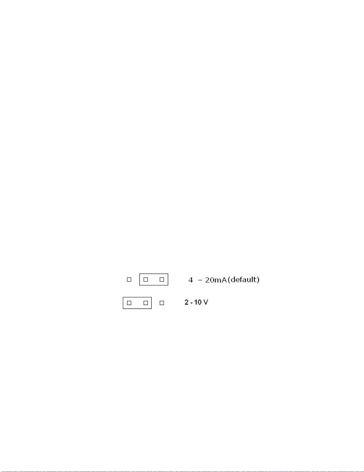
All configuration oftheunit,exceptthesignaloutput mode (setwith J3)isdonethrougha
softwareusermenu system.Themenu systemisprotected byapassword.Toprovide
protection to certainsensitiveparameters, somemenu itemsarehiddenandneed to be
enabled beforetheycanbe accessed.
TheM-20 entersitsmeasurement mode automaticallyafterpowerup.Thefirstconcentration
readingisavailableafter10 seconds. Ifthedefaultconfiguration matchestherequirements
oftheinstallation,thepowerandanalogoutput signalcanbe connected,afterwhichtheunit
will enterservicewhenpowered up.
Iftheinstallation requiresanyofthedefaultsettingsto be altered,itcanbe donethrougha
user-friendlymenu system.Theusersettingsaresaved innon-volatileRAM andwill be
preserved,shouldpowerbe removed duringoperation.
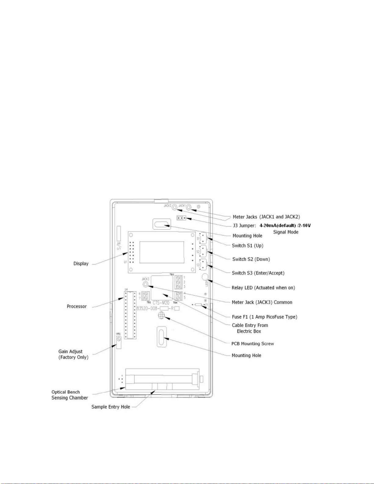
NOTE: It isnot necessaryto opentheenclosureto performcalibration orto change
thedefaultsettings. The‘keypad’switchesarelocated intheupperright side
of theenclosure,andthegas portsarelocated atthebottom (see Figure1).
4.1 UserInterface
TheM-20 userinterfaceconsistsofa2-lineby8-characteralphanumericLCDandathree-
button keypad.
ThetopLCDlineisused to indicatethesettingandthesecondLCD linecontainsthevaluefor
thesetting.Mostsettingsuseanumericvalue(e.g.:0500ppm)andsomeuseatogglestring
(e.g.:“Disable” or“Enable”).
Thekeypadconsistsofthree pushbutton switches. Thepushbutton switchesaremarked S1,
S2andS3.Eachbutton performsaspecificfunction as follows:
S1=Scroll UporIncrement value(topbutton)
S2=Scroll downorDecrement value(middlebutton)
S3=EnterAlteration Mode orAcceptvalue(bottom button)
Thethree switcheswill be referred to as Up(Top),Dn(Middle)andEnter(Bottom).
NOTE: Thepushbutton switchesarerecessed to discourage tamperingwith theunit.
Asmall screwdriver,penorsimilarobjectisrequired to reachtheswitches.
TIP: Twolevelsofkeyrepeatisprovided fortheUpandDnkeys. Aslowrepeat
activatesafterabout half asecondofholdingthekeyin.Afterafew
seconds, thekeywill goto fastrepeatto enablequicksettingof avaluewith
large difference.
4.2 Menu Activation
Press andholdanykeyfor3secondsto activatethepasswordrequestsequence.Selectthe
passwordbyscrollingto theuserpassword(whichisactuallyanumberfrom 0000 to 0255)
usingtheUpandDnkeys. Whenthepasswordisreached,press theEnterkey.
Ifthecorrectpasswordwas entered,thefirstiteminthemenu tree will be shown(see Menu
Tree below).An incorrectpasswordwill be rejected andfollowed byarestartoftheunit,
similarto thepowerupsequence.Enteringnumerousincorrectpasswordscannot causeharm
to theunit,orcauseitto lockout asubsequent validpassword.
NOTE: Thedefaultpasswordis0017,but itcanbe changed bytheuserto any
valuebetween0000 and0255.

M-20 Operation AndMaintenanceManual
83550-003-001 Revision C2008-01-03
10
WARNING: Pleasekeep properrecordofthepassword,shoulditbe
changed from thedefault.Call thefactoryforsupportif itwas
lost.
4.3 Menu ItemSelection
Usethescroll buttons(UporDn)to scroll upanddownthroughthemenu tree.
TIP: Whenthebottom ofthemenu tree isreached,furtherdownwardscrolling
will roll overto thetop.Toreachthebottom ofthemenu tree inquick
fashion,press Upto roll overto thebottom of themenu tree.
4.4 Menu ItemAlteration
ActivatetheMenu ItemAlteration mode bypressingEnterwhiledisplayinganymenu item.
Thedataalteration mode isindicated byanasterisk(*)intheright-handside ofthebottom
LCDdisplayline.Thisindicatesthatthevariablemaybe changed byscrolling(usingUpor
Dn).
Toaccepttheselected value,press Enter.The *will disappear,meaningthatsubsequent use
of UpandDnwill selectthepreviousornextiteminthemenu tree.
4.5 Menu Tree
Themenu tree isexplained inthetablebelow.Theorderofitemsinthetableisas they
appearfrom thefirstitemdownto thelast.
The“JumperJ3”itemisthefirst(ortop)iteminthemenu tree (ormenu itemlist).Togoto
thenextitem,press theDnkey.Togoto thelastiteminthelistfrom the“JumperJ3”item,
press theUpkeyto roll overto thelastitem.
Pleasenotethat,dependingon certainselections, thelength ofthemenu itemlistisaltered.
The“Calibr..”itemaddsthecalibration itemsto thetree when“Enable”isselected.The
“Factory.” itemaddsthefactorysetupitemsto thetree when“Enable” isselected.
Toreturnto themeasuremode andexitfrom themenu tree,scroll upordownto the“Exit”
menu item.
Menu Item List
Item
Name Item Range Default Description/Function
“JumperJ3” “LeftVDC”
or
“RightMA”
“RightMA”Whenusingtheanalogsignal output in
Voltage mode (J3setto theleft),select
“LeftVDC”.
Whenusingthe0-20mA analogsignal
mode (J3setto theright),select
“RightMA”
NOTE:
Thissettingdoesnot change theoutput
mode,but selectstheunitsandvaluesto
be used whensettingtheanalogsignal
end-points.

M-20 Operation AndMaintenanceManual
83550-003-001 Revision C2008-01-03
11
Item
Name Item Range Default Description/Function
“CO2From” 0ppm
to
“CO2To” -500ppm.
0ppm Adjustthelowerppmpoint fortheanalog
signal output instepsof 50ppm.
NOTE:
Thissettingislimited to “CO2To” minus
500ppm.If you want to setitto acertain
valueandscrollingup“getsstuck”,goto
the“CO2To” settingandsetithigher
first.
“CO2To” “CO2From”+500ppm
to
5000ppm
2500ppmAdjusttheupperppmpoint fortheanalog
signal output instepsof 50ppm.
NOTE:
Thissettinghas alowerlimitof “CO2
From” plus500ppm.If you want to setit
to acertainvalueandscrollingdown“gets
stuck”,gobackto the“CO2From” setting
andsetitlowerfirst.
“SigFrom” 0.00Vto 10.00V
or
0.00mA to 20.0mA
NOTE: “SigFrom”
maybe set
higheror
lowerthan
“SigTo”.
4.0mA Adjustthesignal output level at“CO2
From” ppminstepsof 0.05Vor0.10mA.
NOTE:
Theunitsdependon thesettingof
“JumperJ3” above.
NOTE:
Pleasemaintainatleast4.00Vor8.00mA
between“SigTo” and“SigFrom” for
properoperation of theoutput signal.
“SigTo” 0.00Vto 10.00V
or
0.00mA to 20.0mA
NOTE: “SigTo” may
be sethigher
orlowerthan
“SigFrom”.
20.0mA Adjustthesignal output level at“CO2To”
ppminstepsof 0.05Vor0.10mA.
NOTE:
Theunitsdependon thesettingof
“JumperJ3” above.
NOTE:
Pleasemaintainatleast4.00Vor8.00mA
between“SigFrom” and“SigTo” for
properoperation of theoutput signal.
“Clipping” “Enable” or“Disable”“Disable”With clippingsetto “Enabled”,theanalog
output signal will be limited to “SigFrom”
to “SigTo”.If theconcentration drops
below“CO2From”,theoutput signal will
be clipped to “SigFrom”.If the
concentration risesabove“SigTo” the
signal output will not riseabove“SigTo”.
With clippingsetto “Disabled”,thesignal
output will range from 0.00Vto justover
10.00V(or0.0mA to justover20.0mA).
Theoutput will thereforehavearange
beyond“SigFrom” and“SigTo”.

M-20 Operation AndMaintenanceManual
83550-003-001 Revision C2008-01-03
12
Item
Name Item Range Default Description/Function
“AutoZero” “Yes” or“No” “No” When“AutoZero” issetto “Yes”,theunit
will gatherthelowestppmreadinginan
8-dayperiodandsettheunitcalibration
sothatthelowestreadingindicatethe
global average of around360ppm.
When“AutoZero” issetto “No”,theunit
will not adjustitsowncalibration andwork
off thelastmanual orfactorycalibration.
NOTE:
“AutoZero” worksbestinsituationswhere
thebuildingwill purge atnight (orovera
weekend)to theglobal average CO2
concentration.
“Altitude” 0to 9999 feet(ft) 300 ft Thealtitude of theinstalled unitabovesea
level infeet.Canbe setinstepsof 50 ft.
“PassWord” 0000 to 0255 0017 Userpassword,required forenteringthe
menu system.
NOTE:
Pleasemakesureyou keep arecordof the
passwordif changed.
“Relay” “Enable” or“Disable” “Enable” Select“Enable” to updatetherelaystatus
from themeasured concentration.
When“Disable” isselected,therelayis
passiveandremainsnon-energized.
“RelayOn” 0–5000ppm 1000ppmTheconcentration atwhichtherelaywill
be energized.
NOTE:
If “RelayOn” issetlowerthan“RelayOff”,
therelaywill energizewhenthe
concentration dropsbelowthe
concentration setfor“RelayOn”.This
causesandinverted relayaction.
“RelayOff’ 0 –5000ppm
NOTE:
Donot setthedead
bandto be lower
than50ppmto allow
properoperation of
therelay.
950ppm Theconcentration atwhichtherelaywill
be de-energized.
NOTE:
Thedeadbandisthedifferencebetween
“RelayOn” and“RelayOff”.Thedefault
deadbandistherefore50ppm.
“DelayOn” 0–60 minutes 0min “DelayOn” isthetimedelayinminutes
aftertheconcentration passed the“Relay
On” concentration until therelayis
energized.
Thisdelaycanbe used to eliminate
nuisancefanstart-ups. Thedelaycanbe
setinincrementsof 5minutes.

M-20 Operation AndMaintenanceManual
83550-003-001 Revision C2008-01-03
13
Item
Name Item Range Default Description/Function
“DelayOff” 0–60 minutes 0min “DelayOff” isthetimedelayinminutes
aftertheconcentration passed the
“RelayOff” concentration until therelayis
de-energized.
Thisdelaycanbe used to extendthefan
runningtimeaftertheconcentration has
dropped below“RelayOff”.Thedelaycan
be setinincrementsof 5minutes.
“Simulate” 0-5000ppm 500ppm AnyCO2concentration from 0ppmto
5000ppmcanbe simulated bypressing
Enteratthisitem.Whilethe*isshown
thesimulated concentration canbe set
with theUporDnkeys.
Thisfeatureisavailableforevaluatingthe
usersettingsandtestingtheinstallation
(e.g.:thetravel of thevalve,fanspeed,
relaysetpoints, etc. canbe verified.)
“Exit” “Save” or“KeepOld” “Save” Thisisthemenu exitpoint,whichreturns
theunitto themeasurement mode.
TOSAVE YOURCHANGES:
1)Press Enter(*appears).
2)Choose“Save” with UporDn.
3)Press Enterto saveyourchangesin
non-volatileRAM.
4)Aconfirmation string“DataSaved” will
be displayed forafewseconds.
5)Theunitreturnsto measuremode.
TOUNDOYOURCHANGES:
1)Press Enter(*appears).
2)Choose“KeepOld” with UporDn,
whichwill restorethelastsettings
from non-volatileRAM and not save
thenewsettings.
3)Press Enterto dumpyourchangesand
restorethevaluesinnon-volatileRAM.
4)Theunitreturnsto measuremode.

M-20 Operation AndMaintenanceManual
83550-003-001 Revision C2008-01-03
14
Item
Name Item Range Default Description/Function
“Calibr..” “Enable” or“Disable”“Disable” CAUTION: Donot choose“Enable” if
you donot intendto
calibratetheunitand
havecalibration gas
available.
If “Disable” isselected,thisitemisthe
endof themenu list.PressingDnwill roll
overto thetopmenu item.
If “Enable” isselected,themenu listis
extended to include thecalibration menu
items.
Choose“Enable” if you want to calibrate
theunit.
NOTE:
Thisitemwill be defaulted to “Disable”
whenreturningto measuremode.
“ZeroCal” 0ppm±50ppm 0ppm NOTE:
Pleasereferto the Calibration section in
thetext belowformoreinformation.
PROCEDURE:
1)Apply100%pureNitrogengas to the
unit,usinganM-20 calibration kit.
2)Press Enterandsee the*appearon
thebottom LCD line.
3)Waitfortheconcentration to stabilize,
itshouldbe lowandnot too farfrom
0ppm.
4)Press Dn(orUp)to settheindicated
concentration to 0ppm.TheZeroppm
point isnowcalibrated.
5)If theconcentration changesandre-
stabilizemorethan50ppmfrom zero,
press Up(orDn)again.
6)Repeatstep 5)until theconcentration
showsastablepatternbetween0ppm
and50ppm.Trynot to accepta
negativeconcentration,unless itis
small (-10ppmto –1ppm).
7)Press Enterto accept(*disappears).

M-20 Operation AndMaintenanceManual
83550-003-001 Revision C2008-01-03
15
Item
Name Item Range Default Description/Function
“SpanCal” 2500ppm±50ppm 2500ppm NOTE:
Pleasereferto the Calibration section in
thetext belowformoreinformation.
EXCEPTION:
It isalsopossibleto calibratethespan
with adifferent spangas concentration
than2500ppm.In suchcases, replace
2500ppminthisprocedurewith the
chosenspangas concentration (e.g.:
5000ppm).Theunitwill havenon-linear
responseforspancalibration above
5000ppm.
PROCEDURE:
1)Apply2500ppmCO2(balance
Nitrogen)to theunit,usinganM-20
calibration kit.
2)Press Enterandsee the*appearon
thebottom LCD line.
3)Waitfortheconcentration to stabilize,
itshouldbe 2500ppm±1000ppm.
4)Press Dn(orUp)to settheindicated
concentration to 2500ppm±50ppm.
Asyou getcloserto 2500ppm,reduce
thenumberof UporDnkeypresses
betweenmeasurements.
5)If theconcentration changesandre-
stabilizemorethan50ppmfrom
2500ppm,press UporDnto trimthe
concentration.
6)Repeatstep 5)until theconcentration
showsastablepatternbetween
2450pmand2550ppm.
7)Press Enterto accept(*disappears).

M-20 Operation AndMaintenanceManual
83550-003-001 Revision C2008-01-03
16
Item
Name Item Range Default Description/Function
“Factory.” “Enable” or“Disable”“Disable”
CAUTION: Do not choose “Enable” if
you are notfamiliarwith
technical procedures.
Someof theitemsinthe
FactoryMenu RequireZero
Gas, andsomerequirea
calibrated DMM.
If “Disable” isselected,thisitemisthe
endof themenu list.PressingDnwill roll
overto thetopmenu item.
If “Enable” isselected,themenu listis
extended to include thefactorysetup
menu items.
Choose“Enable” if you want to updatethe
factorysettingsof theunit.
NOTE:
Thisitemwill be defaulted to “Disable”
whenreturningto measuremode.

M-20 Operation AndMaintenanceManual
83550-003-001 Revision C2008-01-03
17
Item
Name Item Range Default Description/Function
“SigCal” 0800 –1023
NOTE:
The indicated value isa
proportionof 1023,
whichresultsina
desired outputvoltage
orcurrent.
21.5mA =1023/1023
20mA =951/1023
951 NOTE:
Calibratingthissettinginthemode
required forthespecificapplication will
deliverbetteraccuracyforthesignal level.
TIP1:
If you areusingthe0-20mA output mode
andwant to performan“in-circuit”
calibration,donot disconnectthesignal
output linesfrom thetargetsystemand
connecttheDMM positiveprobe to
“JACK1” andthenegativeprobe to
“JACK2”.Proceed as described below,but
keep theDMM probesconnected as
described here.
TIP2:
Whenusingthe0-10Vmode,thesignal
connectionscanbe leftinplace,resulting
inacalibration thatincludestheinput
impedanceof thetargetsystem.
REQUIRED:
1)Calibrated DMM (3½or4½digit).
2)Philipsscrewdriverto opencover.
POCEDURE:
1)Disconnectthe“SIG” lineon “TB1” if
you are not performinga0-20mA “in-
circuit” calibration (see TIP1andTIP
2above).
2)Decide if you want to calibratethe
signal output for0-10Vor0-20mA.
SetJ3to matchyourpreference.
3)Selectthescaleon theDMM to your
preference(0-40mA scalefor0-20mA,
and0–10Vscalefor0-10Vmode).
4)Insertthenegativeleadof theDMM
into the“JACK3” testpoint on the
circuitcard(see TIP1above).
5)Insertthepositiveleadof theDMM
into the“JACK2” testpoint on the
circuitcard(see TIP1above).
6)Press Enter(*appears).Thesignal
output will riseto 20mA or10V.
7)UseUporDnto trimthesignal output
to 10.01Vor20.01mA.
8)Press Enter(*disappears).
TIP3:
You mayneed to findacompromise
betweenthelowerandupperpartsof the
range.Whennot ineditmode (*isoff),
the“SigFrom” level will be atthesignal
output.Trimtheadjustment if necessary
to haveaclosermatchfor“SigFrom”.

M-20 Operation AndMaintenanceManual
83550-003-001 Revision C2008-01-03
18
Item
Name Item Range Default Description/Function
“GlobAve” 0000 –5000ppm 360ppm Thisitemisused bytheAutoZero
function.Change itonlyif theglobal
average changes(guaranteed overtime
to change)orif you want to usea
different valuefortheAutoZerofunction.
TIP:
If you havestatistical datashowingthat
thebuildingpurgesto,say400ppm,over
an8-dayperiod,you canchange “Glob
Ave” to apseudoglobal average of
400ppmto obtainmoreaccurateauto
zeroing.
“NitroRef” 3850mV –3950mV 3800mV CAUTION:
Thisitemadjuststhegainof thefront-end
amplifieranditszeroreference.
Adjustment isrequired duringproduction,
orif thelampbrightness has drifted over
time.
REQUIRED:
1)100%Nitrogenused forZeroCal.
2)2500ppmCO2spangas.
3)M-20 Calibration Kit.
4)Small flatscrewdriver.
PROCEDURE:
1)Hookupthecalibration kitas when
performingaZeroCal.
2)Press Enter(*appears).ThemV
readingwill startupdatingas thelamp
cycleson andoff atan1secondrate.
3)Checktheindicated mV readingafter
itstabilizes. If thereadingisstable
between3850mV and3950mV,
proceed to item5).
4)AdjustVR1until thereadingisstable
between3850mV and3950mV.The
preferred targetreadingis3900mV.
5)Press Enter(*disappears).
6)PerformaZeroCal andSpanCal
(required)as described above.

M-20 Operation AndMaintenanceManual
83550-003-001 Revision C2008-01-03
19
Item
Name Item Range Default Description/Function
“Defaults” “User” or“All” “User” WARNING: Choosing“All” will restore
defaultsto all itemsinthe
menu tree,includingthe
factorysettings.
UserSettings:
Toloaddefaultsto all useritems, press
Enter(*appears)choose“User” with Up
orDn,andpress Enterto accept.A
confirmation string“DefaultsRestored”
will be shownforafewseconds. The
calibration settingswill not be changed.
All Settings (includescalibration):
Toloaddefaultsto all items, press Enter
(* appears)choose“All” with UporDn,
andpress Enterto accept.A
confirmation string“DefaultsRestored”
will be shownforafewseconds.
Performafull factoryandgas
calibration torestoretheunitto
correct operation.
TIP:
If you changed yourmindafterrestoring
“All” defaults, dothefollowing:
1)Gostraight to the“Exit” menu item
bypressingup(while*isnot
shown).
2)Press Enteratthe“Exit” menu item
(*appears).
3)Choose“KeepOld”.
4)Press Enterto accept.
5)Therestored defaultswill not be
saved to non-volatileRAM.All other
changeswill alsobe lost.
6)Theunitreturnsto themeasure
mode.
Table of contents
Popular Gas Detector manuals by other brands

Emerson
Emerson MRLDS-450 Installing and operating instructions

Katranji
Katranji EM282 user manual

Oldham
Oldham Surveyor 4B Installation, operating and maintenance manual

FHF
FHF YL 6 Installation

Bosean Electronic Technology
Bosean Electronic Technology BH-90 user manual

Kidde
Kidde KN-COP-DP-10YL-AQ-WF-CA user guide