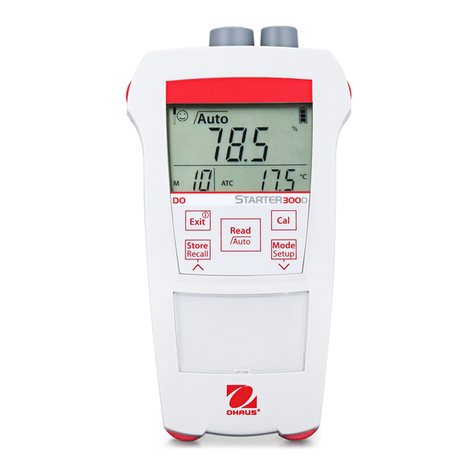
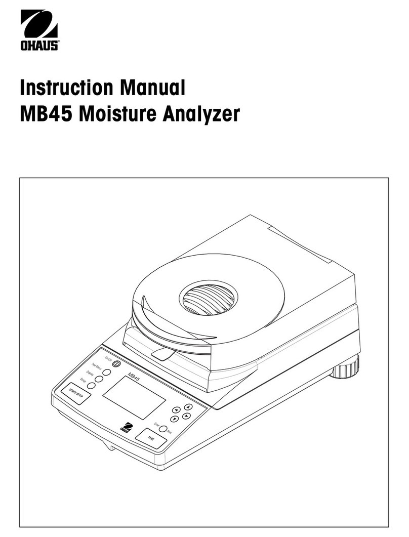
OHAUS 7000 Series User manual

SERVICE MANUAL
7000 Series
T72XW Indicators
T72XW
Ohaus Corporation 19A Chapin Road, P.O. Box 2033, Pine Brook, NJ 07058-2033 (973) 377-9000


SERVICE MANUAL
7000 Series T72XW Indicators:
T72XW
The information contained in this manual is believed to be accurate at the time of publication, but Ohaus
Corporation assumes no liability arising from the use or misuse of this material. Reproduction of this
material is strictly prohibited.
Material in this manual is subject to change.
© Copyright 2014 Ohaus Corporation, all rights reserved.
TM Registered trademark of Ohaus Corporation.

TABLE OF CONTENTS
Ohaus Corporation www.ohaus.com 1 7000 Series T72XW Indicators Service Manual
CHAPTER 1 GETTING STARTED Page No.
1.1 Introduction..............................................................................................................1-1
1.2 Service Facilities......................................................................................................1-1
1.3 Tools and Test Equipment Required........................................................................1-2
1.3.1 Special Tools and Test Equipment List.............................................................1-2
1.3.2 Standard Tools and Test Equipment List ..........................................................1-2
1.4 T72XW Physical Dimensions ...................................................................................1-2
1.5 Specifications...........................................................................................................1-4
1.6 Main Board Wiring Connections...............................................................................1-5
1.6.1 Analogue Load Cell Connection........................................................................1-5
1.6.2 COM1 Serial Port Connection...........................................................................1-7
1.6.3 PCB Switch Setting...........................................................................................1-8
1.6.4 SD Card Installation..........................................................................................1-9
1.7 Overview of the Controls........................................................................................1-10
1.7.1 Display and Keyboard.....................................................................................1-10
1.7.2 Display Layout ................................................................................................1-10
1.7.3 Front Panel Key..............................................................................................1-10
1.8 Operation Terminal ................................................................................................1-11
1.8.1 Overview.........................................................................................................1-11
1.8.2 Display Elements and Keypad Operation........................................................1-11
1.8.3 Display Elements............................................................................................1-11
1.8.4 Keypad Operation...........................................................................................1-13
1.8.5 Language Selection........................................................................................1-16
1.8.6 Configuration ..................................................................................................1-16
1.9 Calibration..............................................................................................................1-17
1.9.1 GEO Code......................................................................................................1-17
1.9.2 Set Zero..........................................................................................................1-19
1.9.3 Set Span.........................................................................................................1-19
1.9.4 Analogue Saturation Test................................................................................1-20
1.10 Communication......................................................................................................1-20
1.10.1 Serial ..............................................................................................................1-21
1.10.2 COM1.............................................................................................................1-21
1.10.3 Baud...............................................................................................................1-21
1.10.4 Data................................................................................................................1-21
1.10.5 Parity..............................................................................................................1-21
1.10.6 Flow Control...................................................................................................1-21
1.10.7 COM2/USB......................................................................................................1-23
1.10.8 Baud................................................................................................................1-23
1.10.9 Data Bits..........................................................................................................1-23
1.10.10 Parity.............................................................................................................1-23
1.10.11 Flow Control ..................................................................................................1-23
1.10.12 Interface ........................................................................................................1-23
1.10.13 Network.........................................................................................................1-24
1.10.14 Ethernet.........................................................................................................1-24
1.10.15 MAC Address ................................................................................................1-24
1.10.16 DHCP Address..............................................................................................1-24
1.10.17 IP Address.....................................................................................................1-24
1.10.18 Gateway Address..........................................................................................1-24
1.10.19 Print Client.....................................................................................................1-25
1.10.20 Server IP Address .........................................................................................1-25
1.10.21 Server TCP Port............................................................................................1-25

TABLE OF CONTENTS
7000 Series T72XW Indicators Service Manual 2 Ohaus Corporation www.ohaus.com
CHAPTER 1 GETTING STARTED (Continue) Page No.
1.10.22 Reset..............................................................................................................1-25
CHAPTER 2 TROUBLESHOOTING
2.1 Introduction..............................................................................................................2-1
2.2 Diagnostic Guide......................................................................................................2-1
2.3 Error Codes And Error Message..............................................................................2-3
2.4 troubleshooting ........................................................................................................2-5
2.4.1 Blank Display....................................................................................................2-5
2.4.2 Power Test.......................................................................................................2-5
2.4.3 Problem Diagnosis ...........................................................................................2-5
2.5 Internal Diagnostics..................................................................................................2-7
2.5.1 Display Test.......................................................................................................2-7
2.5.2 Keyboard Test...................................................................................................2-8
2.6 Scale Diagnostics ....................................................................................................2-8
2.7 Serial Test................................................................................................................2-8
2.8 Discrete I/O Test....................................................................................................2-10
2.9 System Backup and Restore..................................................................................2-11
2.10 Backup to SD Memory Card...................................................................................2-12
2.11 Restore From SD Memory Card.............................................................................2-12
2.12 Master Reset..........................................................................................................2-13
2.13 Updating Firmware.................................................................................................2-14
CHAPTER 3 MAINTENANCE PROCEDURES
3.1 Preventive Maintenance...........................................................................................3-1
3.1.1 Cleaning and Maintenance ...............................................................................3-1
3.2 Replace of Major Components.................................................................................3-2
3.2.1 Opening the Enclosure .....................................................................................3-2
3.2.2 Closing the Enclosure.......................................................................................3-3
3.2.3 Main Printed Circuit Board (PCB) Replacement................................................3-3
3.2.4 Back Light LCD Display Replacement...............................................................3-5
3.2.5 Membrane Switch Replacement .......................................................................3-6
3.3 Wiring Connection....................................................................................................3-7
3.3.1 Analogue Load Cell Connections......................................................................3-7
3.4 PCB Switch Setting..................................................................................................3-9
3.4.1 Main PCB Swicthes ..........................................................................................3-9
3.5 SD Card Installation...............................................................................................3-10
3.6 Securing the Enclosure..........................................................................................3-11
CHAPTER 4 PARTS LISTS & DIAGRAMS
4-17000 Series T72XW Indicator: Housing & Internal Parts ..........................................4-2

TABLE OF CONTENTS
Ohaus Corporation www.ohaus.com 3 7000 Series T72XW Indicators Service Manual
APPENDIX A GEOGRAPHICAL (GEO)
Appendix A. Geographical Adjustment Values .................................................................A-1
APPENDIX B COMMUNICATIOS
Appendix B. Communications ..........................................................................................B-1
B.1 Serial Interface parameters.....................................................................................B-1
B.2 Demand Output Mode.............................................................................................B-1
B.3 Output Template.....................................................................................................B-2
B.4 Continues Output Mode ..........................................................................................B-3
B.5 Standard Interface Command Set (SICS) Protocol..................................................B-3
B.6 Version Number of the MT-SICS.............................................................................B-3
B.7 Command Formats .................................................................................................B-4
B.8 Response Formats..................................................................................................B-4
B.9 Format of the Response with Weight Value ............................................................B-4
B.10 Format of the Response without Weight Value........................................................B-5
B.11 Format of the Error Message ..................................................................................B-6
B.12 Command and Response........................................................................................B-6
B.13 Reset ......................................................................................................................B-7
B.14 Quotation Mark (“ ”).................................................................................................B-7
B.15 Commands and Responses MT-SICS Level 0........................................................B-7
B.15.1 10-Inquiry of All Implemented MT-SICS Commands....................................B-7
B.15.2 l1-Inquiry of MT-SCIS Level and MT-SICS Versions...................................B-8
B.15.3 Inquiry od Data ...........................................................................................B-9
B.15.4 Inquiry of SW Version .................................................................................B-9
B.15.5 Inquiry of Serial Number ...........................................................................B-10
B.15.6 Send Stable Weight Value........................................................................B-10
B.15.7 Sl-Send Weight Value Immediately...........................................................B-11
B.15.8 SIR-Send Weight Value Immediately and Repeat.....................................B-11
B.15.9 Z-Zero.......................................................................................................B-12
B.15.10 Q-Reset..................................................................................................B-12
B.16 Commands and Responses MT-SCIS Level 1......................................................B-13
B.16.1 SR-Send Weight Value on Weight Change (Send and Repeat)................B-13
B.16.2 T-Tare.......................................................................................................B-14
B.16.3 TA-Inquiry/Enter Tare Value .....................................................................B-14
B.16.4 TAC-Clear Tare Value...............................................................................B-15
B.16.5 Tl-Tare Immediately..................................................................................B-15
B.17 Report...................................................................................................................B-15
B.17.1 Alibi Memory.............................................................................................B-16
B.17.2 Total Report..............................................................................................B-16
B.18 Variable Access....................................................................................................B-17
B18.1 Connections...............................................................................................B-17
B.18.2 Commands ...............................................................................................B-17
B.18.3 Individual Variables...................................................................................B-17
B.18.4 Blocks of Variables ...................................................................................B-18
B.18.5 Variable List..............................................................................................B-19
B.18.5.1 Scale Status (read only)...............................................................B-19
B.18.5.2 Dl0 and Target Status (read only) ................................................B-20

TABLE OF CONTENTS
7000 Series T72XW Indicators Service Manual 4 Ohaus Corporation www.ohaus.com
APPENDIX B COMMUNICATIOS (Continue)
B.18.5.3 Terminal Information (read only)...........................................B-20
B.18.5.4 Terminal Commands (write only) ..........................................B-22
B.18.5.5 Setup-Scale (read and write).................................................B-23
B.18.5.6 Setup-Application (read and write)........................................B-25
B.18.5.7 Setup-Terminal (read and write)............................................B-29
B.18.5.8 Setup-Communication (read and write).................................B-31
B.18.5.9 Setup-Maintenance (read and write)......................................B34
B.18.5.10 Setup-Target Values (read and write) ...................................B-35

CHAPTER 1 GETTING STARTED
7000 Series T72XW Indicator Service Manual 1-1 Ohaus Corporation www.ohaus.com
1.1 INTRODUCTION
This service manual contains the information needed to perform routine maintenance and
service on the Ohaus T72XW Indicators. The contents of this manual are contained in five
chapters:
Chapter 1 Getting Started –Contains information regarding service facilities, tools and test
equipment, specifications, hardware setup or disassembly, operating the Indicator, scale setup
and calibration, and configuring the Indicator’s communication and Legal-for-Trade menus.
Chapter 2 Troubleshooting –Contains a diagnosis/diagnostics chart and error code table.
Chapter 3 Maintenance Procedures –Contains preventive maintenance procedures and
disassembly, repair and replacement procedures.
Chapter 4 Testing –Contains an operational test, segment display test, performance tests and
adjustments.
Chapter 5 Drawings and Parts Lists –Contains exploded views of T72XW Indicators,
identifying all serviceable components.
Before servicing the indicator, you should be familiar with the Instruction Manual which is
packed with every indicator.
1.2 SERVICE FACILITIES
To service an indicator, the service area should meet the following requirements:
Must be protected from electrostatic discharge.
Should be temperature controlled and meet the indicator specifications for temperature
environmental requirements. See specifications for temperature range.
Must be free of vibrations such as fork lift trucks close by, large motors, etc.
Must be free of air currents or drafts from air conditioning/heating ducts, openwindows,
people walking by, fans, etc.
Area must be clean and air must not contain excessive dust particles.
Work surface must be stable and level.
Work surface must not be exposed to direct sunlight or radiating heat sources.

CHAPTER 1 GETTING STARTED
Ohaus Corporation www.ohaus.com 1-2 7000 Series T72XW Indicator Service Manual
1.3 TOOLS AND TEST EQUIPMENT REQUIRED
In order to properly service the Indicator, certain special tools and test items are required in
addition to standard electronic tool kits. These items are listed as follows:
1.3.1 Special Tools and Test Equipment List
1. Ohaus Scale Base.
2. Load Cell Simulator optional.
3. Computer with RS232 Interface.
4. RS232 Interface cable.
5. Data Printer for use with RS232 communications.
6. ESD work station or mat.
1.3.2 Standard Tools and Test Equipment List
1. Standard Electronics Tool Kit
2. Digital Voltmeter (DVM), with clip-on probes. Input impedance of at least 10 megohms in
the 1 Volt dc position.
3. Soldering Iron, solder and flux remover.
1.4 Physical Dimensions
Figure 1-1. Physical Dimensions, T72XW.
Mounting
Bracket
Adjusting
Knobs

CHAPTER 1 GETTING STARTED
7000 Series T72XW Indicator Service Manual 1-3 Ohaus Corporation www.ohaus.com
1.5 SPECIFICATIONS
TABLE 1-1. SPECIFICATIONS
.
T72XW Specifications
Enclosure Type
Stainless steel, configurable as desk top or wall mount enclosure
Dimensions (w h d)
283 mm x 232 mm x 86 mm (11.1 in. x 9.1 in. x 3.4 in.)
Shipping Weight
AC Version: 3.4 kg (7.5 lb)
Environmental Protection
IP66 (comparable to Type 4x)
Operating Environment
The terminal can be operated at temperatures ranging from 10°to 40°C (14°to
104°F) at 10% to 95% relative humidity, non-condensing.
Hazardous Areas
The T72XW terminal cannot be operated in areas classified as Hazardous because
of combustible or explosive atmospheres in those areas.
Power
Operates at 85–264 VAC, 49–61 Hz and includes a power cord configured for the
country of use.
Power Consumption
Refer to Error! Reference source not found. Table 0-1.Values shown are with
internal COM2/DIO option and Ethernet option installed and load cell input loaded
with 8 x 350load cells.
Display
Backlit 240 x 96 dot graphic LCD including weight display, weight units, gross/net
indication and graphic symbols for motion and center of zero, SmartTrac, operator
prompts and data entry display. Update rate of 12 updates per second.
Basic weight mode: 27 mm (1.1 in) high weight display
Application mode: 20 mm (0.8 in) high weight display
Weight Display
Maximum displayed resolution of 50,000 divisions.
Scale Types
Analog load cells
Number of Cells
From one to ten 350-ohm load cells (2 or 3 mV/V)
Number of Scales
One
Analog/Digital Update Rate
Internal analog: 366 Hz
Load Cell Excitation Voltage
10 VDC
Minimum Sensitivity
0.1 microvolt per increment
Keypad
25 keys; polyester overlay (PET) with polycarbonate display lens
Communications
Serial Interfaces
Standard: One isolated serial port (COM1) RS-232, 300 to 115,200 baud
Optional isolated serial port: (COM2) RS-232/485, 300 to 115,200 baud
Optional USB port: serial port bridge, 300 to 115,200 baud
Ethernet Interface
Optional Ethernet port: 10/100 TCP/IP port
Protocol
Serial Inputs: ASCII commands for CTPZ (Clear, Tare, Print, Zero), SICS (most
level 0 and level 1 commands)
Serial Outputs: Continuous, Extended continuous, Demand (limited formats),

CHAPTER 1 GETTING STARTED
Ohaus Corporation www.ohaus.com 1-4 7000 Series T72XW Indicator Service Manual
.
T72XW Specifications
Reports, SICS (most level 0 and level 1 commands) or Variable Access
Approvals
Weights and Measures
USA:
NTEP Class III - 10,000d;
Canada:
Class III - 10,000d;
Europe:
Class III, 6000e;
OIML:
Class III, 6000e;
Product Safety
UL, cUL, CE
Table 0-2: T72XW Power Consumption
Input
Voltage
I (mA)
P (W)
5V/50 Hz
167
7.9
110 V/50 Hz
133
7.7
240 V/50 Hz
64
7.9
264 V/50 Hz
59
7.9
85 V/60 Hz
163
7.9
110 V/60 Hz
128
7.7
240 V/60 Hz
62
7.9
264 V/60 Hz
58
8.0

CHAPTER 1 GETTING STARTED
7000 Series T72XW Indicator Service Manual 1-5 Ohaus Corporation www.ohaus.com
1.6 Main Board Wiring Connections
Once the T72XW terminal harsh enclosure is open, connections can be made to the terminal
strips on the main board, as shown in Figure 1-.
Figure 1-2: T72XW Main Board Connections, AC Model
1.6.1 Analog Load Cell Connections
WARNING!
TO AVOID DAMAGE TO THE PCB OR LOAD CELL, REMOVE POWER FROM THE
T72XW TERMINAL AND WAIT AT LEAST 30 SECONDS BEFORE CONNECTING OR
DISCONNECTING ANY HARNESS.
Load cell connections are made to the load cell connector located on the main board as shown
in Figure 1-2.
The AC version of the T72XW terminal is designed to power up to ten 350-ohm load cells (or a
minimum resistance of approximately 35 ohms). The battery version of the T72XW terminal is
designed to power up to four 350-ohm load cells (or a minimum resistance of approximately 87
ohms). To confirm that the load cell load for this installation is within limits, the total scale
resistance (TSR) must be calculated. To calculate TSR:
TSR =
Load Cell Input Resistance (Ohms)
Number of Load Cells
Ensure that the TSR of the load cell network to be connected to the T72XW has a resistance
greater than the minimum values listed above before connecting the load cells. If the resistance
is below the minimum, the T72XW will not operate properly.
DIP
switches
AC
power
connect
or
Load cell
connector
r
Option 1
connector
Option 2
connector

CHAPTER 1 GETTING STARTED
Ohaus Corporation www.ohaus.com 1-6 7000 Series T72XW Indicator Service Manual
In addition, the maximum cable distance must be reviewed. Table 0- provides recommended
maximum cable lengths based on TSR and cable gauge.
Table 0-3: Recommended Maximum Cable Lengths
TSR (Ohms)
24 Gauge
(meters/feet)
20 Gauge
(meters/feet)
16 Gauge
(meters/feet)
350
243/800
610/2000
1219/4000
87 (4-350 cells)
60/200
182/600
304/1000
43 (8-350 cells)
30/100
91/300
152/500
35 (10-350
cells)
24/80
60/200
120/400
The T72XW terminal is designed to support both 2mV/V and 3mV/V load cells from the same
circuitry. A load cell output rating selection jumper is not required.
Figure 0- shows the terminal definitions for the analog
load cell terminal strip. Note that when using four-wire load cells, jumpers must be placed
between the +Excitation and +Sense terminals and between the Excitation and Sense
terminals.
Figure 0-3: Load Cell
Termination
Note: For the standard four-wire cable: If an increase in load results in a decrease in weight
display, reverse the signal wires (+SIG and SIG)

CHAPTER 1 GETTING STARTED
7000 Series T72XW Indicator Service Manual 1-7 Ohaus Corporation www.ohaus.com
1.6.2 COM1 Serial Port Connections
The COM1 port provides an RS-232 connection for external serial devices. Figure 0- indicates
which terminal carries which signal on the COM1 port. Make the connections as necessary.
Terminal
Signal
TxD
Transmit RS-232
RxD
Receive RS-232
Gnd
Logic Ground
Figure 0-4: COM1 Port Signal
An example of connecting via RS-232 to external equipment is shown in Figure 0-. Make the
connections as necessary.
NOTES:
1. USE ONLY SHIELDED CABLE.
2. MAXIMUM CABLE LENGTH: 50 FEET (15 METERS).
3. WIRE SIZE: 18 AWG (.823 mm2) MAXIMUM
24 AWG (0.205 mm2) MINIMUM.
Figure 0-5: Sample COM1 Connections

CHAPTER 1 GETTING STARTED
Ohaus Corporation www.ohaus.com 1-8 7000 Series T72XW Indicator Service Manual
1.6.3 PCB Switch Settings
PCB switch settings are described in this section, including settings for main PCB switches and
the discrete I/O switch.
Main PCB Switches
A six position switch block (Figure 0-) is located on the main PCB. These switches function as
shown in
Figure 0-6: Location of Switch Block 1 on the Main PCB
Table 0-4: Switch 1 Functions
Switch
Functions
Notes
SW1-1
Metrology Security Switch (legal for trade)
When in the ON position, this switch prohibits changes to
metrological parameters in setup. This must be ON for
“approved” applications
This is true even if the Scale
Approval parameter is
selected as “None” in setup.
SW1-2
Master Reset
Set in the ON position and power cycle to perform a
master reset of all data in the terminal
Set in the OFF position during normal operation.
When a Master Reset is
performed, set SW1-4 to ON
to reset metrologically
significant data, such as scale
calibration, GEO code, etc.
SW1-3
Flash Software
Set in the ON position for software download
Set in the OFF position during normal operation
SW1-4
Reset Calibration
Set in the ON position to reset calibration during a master
reset
Set in the OFF position to retain current calibration values
during a master reset
Works with switch SW1-2

CHAPTER 1 GETTING STARTED
7000 Series T72XW Indicator Service Manual 1-9 Ohaus Corporation www.ohaus.com
Switch
Functions
Notes
SW1-5
Not used
SW1-6
Not used
When both SW1-2 and SW1-4 are positioned ON and AC power is applied to the terminal, a
Master Reset function will be initiated. This procedure will erase all programming in the terminal
and return all settings back to factory default values. This process is described in the T72XW
Technical Manual, Chapter 4, Service and Maintenance.
1.6.4 SD Card Installation
The SD memory card can be used for additional storage in the Checkweighing and Counting
applications, and must be installed if the Vehicle Application is used. Figure 0- shows the
installation of an SD card into the socket on the edge of the T72XW main board.
Figure 0-7: Sliding an SD Card into the SD Socket (left); SD Card Installed (right)

CHAPTER 1 GETTING STARTED
Ohaus Corporation www.ohaus.com 1-10 7000 Series T72XW Indicator Service Manual
1.7 OVERVIEW OF THE CONTROLS
This section contains information on the basic operation of the Indicator which includes the
Display and Keyboard explanations of the indicator.
1.7.1 Display and Keyboard
The T72XW terminal uses a graphic, transflective type Liquid Crystal Display (LCD) with a white
LED backlight. The front panel including the display and keypad is shown in Figure 0-8.
Figure 0-8: T72XW Front Panel Layout
1.7.2 Display Layout
At the top of the display, a single system line displays terminal status and operator error
displays and messages. Time and date and the status of the Digital I/O can be displayed in this
area, when so configured in setup.
Below the system line is the weight display. During normal, basic weighing operation, the
T72XW terminal display shows the Gross or Net weight in the larger 28.5mm (1.1 in.) size.
When one of the applications is running, the weight is shown in 20mm (0.8 in.) high characters.
Below the weight display is a single line to display the weight units, the weight legend, the
center of zero icon, weight range and motion icon. Tare values also appear on this line, to the
left of the display.
At the bottom of the normal basic weighing display is a line used for data entry. For display
operation during setup, refer to Chapter 3, Configuration in the Instruction Manual.
LCD display
Alphanumeric
keypad
Scale Function
keys
Print/Enter
key
ON/OFF key
Navigation
keys
Operational
keys

CHAPTER 1 GETTING STARTED
7000 Series T72XW Indicator Service Manual 1-11 Ohaus Corporation www.ohaus.com
1.7.3 Front Panel Keys
The T72XW terminal provides a total of 25 keys as an operator interfaces. The ON/OFF key,
four scale function keys and three operational keys are positioned under the display while the
alpha-numeric keys are positioned to the right of the display. The print/enter key and navigation
keys are located at the bottom right of the display. These keys are used to enter the setup
menu, to navigate and select setup elements, and to enter values in setup as described in
Chapter 3, Configuration in the Instruction Manual.
1.8 Operation: Terminal
1.8.1 Overview
This chapter provides information about the basic functionality of the T72XW terminal, including
display operation, keypad functions and menu navigation.
Operation of the terminal varies depending on which functions are enabled, and on the
configuration of parameters in setup. Configuration is described in Chapter 3, Configuration:
Terminal in the Instruction Manual.
1.8.2 Display Elements and Keypad Operation
Refer to Figure 1-8 for an overview of the layout of the front panel of the T72XW.
1.8.3 Display Elements
When in the weighing mode, the display is used for indicating the weight value and other types
of information related to the weight. Refer to Figure 1-9.
Figure 1-9: Elements of the Display
The symbols that may appear on the display are described in Table 1-5.

CHAPTER 1 GETTING STARTED
Ohaus Corporation www.ohaus.com 1-12 7000 Series T72XW Indicator Service Manual
Table 1-5: Main Display Symbols
Symbol
Explanation
I/O status* (On and Off)
2 inputs, 4 outputs
= Input or output active
Time and date*
Numeric, Upper case alpha,
lower case alpha and Decimal
data entry mode.
Decimal mode is available
only in the template string
entry screens
Tare type and value indicator
Motion on platform
Center of zero
Weighing range*
Unit (kg, lb, oz, g, ton, t)
Bruto/Gross or Net operating
mode
Prompt for ID entry and entry
field
* These elements appear if configured to do so in setup.

CHAPTER 1 GETTING STARTED
7000 Series T72XW Indicator Service Manual 1-13 Ohaus Corporation www.ohaus.com
1.8.4 Keypad Operation
The front panel keys are used to operate and configure the T72XW.
Alphanumeric Keypad
The T72XW permits the entry of both alphabetical and numeric data, using the 12-element
keypad to the right of the display.
Figure 1-10: Alphanumeric Keypad
Key Timeout Period
When using the keys to enter data, after a set amount of time elapses the terminal accepts the
character that is currently displayed, and moves to the next position. Pressing the key without
allowing the Key Timeout period to elapse cycles through the current option for that key. For
instance, when the 4 key is pressed in mode, the display cycles through g, h and i.
The length of this timeout period is measured in tenths of a second, and can be configured in
setup at Terminal > Terminal\Device.
SHIFT Key
The SHIFT key is used to determine the type of entry made when a key is pressed. Four
entry modes are available:
Numerical (123)
Upper case alphabetical (ABC)
Lower case alphabetical (abc).
Decimal entry (Dec) (This mode is available only when entering template strings.)
The current entry mode is indicated at the upper right corner of the display (Figure 1-9,Table 1-
5).
SHIFT
ZERO and SPACE
DECIMAL POINT, PERIOD, and
additional punctuation characters
1, HYPHEN, COMMA,
SLASH, &
Other manuals for 7000 Series
1
This manual suits for next models
1
Table of contents
Other OHAUS Measuring Instrument manuals

OHAUS
OHAUS Defender 3000 User manual

OHAUS
OHAUS T51 Use and care manual

OHAUS
OHAUS MB35 User manual

OHAUS
OHAUS i-DT33XW User manual

OHAUS
OHAUS MB27 User manual

OHAUS
OHAUS T31P User manual

OHAUS
OHAUS Defender 6000 User manual

OHAUS
OHAUS STARTER 2100 User manual

OHAUS
OHAUS TD52 User manual

OHAUS
OHAUS CKW-55 User manual

OHAUS
OHAUS Defender T24PE User manual

OHAUS
OHAUS STARTER 3100C User manual

OHAUS
OHAUS CD-1 User manual

OHAUS
OHAUS STARTER 300C User manual

OHAUS
OHAUS TD52 User manual

OHAUS
OHAUS MB90 User manual

OHAUS
OHAUS MB23 User manual

OHAUS
OHAUS TD52 User manual

OHAUS
OHAUS MB95 User manual

OHAUS
OHAUS Ranger 3000 Series User manual