OHAUS Defender I-D33P15B1R1 User manual

DefenderTM 3000 Indicators
Instruction Manual
i-DT33P
i-DT33XW


Defender 3000 Indicators EN-1
Table of Contents
1. INTRODUCTION ................................................................................................................................................3
1.1. SAFETY PRECAUTIONS ................................................................................................................................................... 3
1.2. INTENDED USE ............................................................................................................................................................ 3
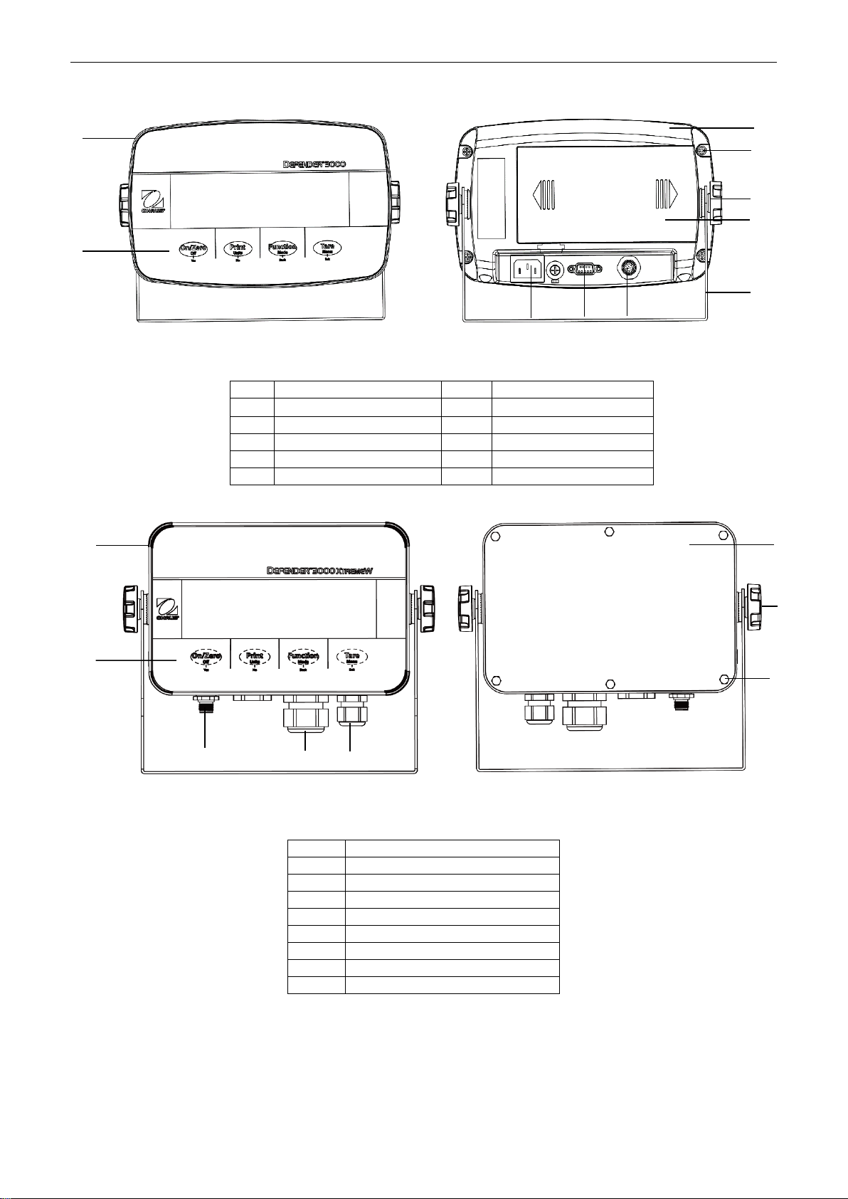
1.3. OVERVIEW OF PARTS AND CONTROLS .............................................................................................................................. 4
1.4. MAINBOARD ............................................................................................................................................................... 5
1.5. CONTROL FUNCTIONS ................................................................................................................................................... 6
2. INSTALLATION ..................................................................................................................................................8
2.1 UNPACKING ................................................................................................................................................................ 8
2.2 EXTERNAL CONNECTIONS............................................................................................................................................... 8
2.2.1 Battery Power Supply...................................................................................................................................... 8
2.2.2 AC Power Supply ............................................................................................................................................. 8
2.3 INTERNAL CONNECTIONS ............................................................................................................................................... 9
2.3.1 Open the Housing............................................................................................................................................ 9
2.3.2 EasyConnectTM Indicator ............................................................................................................................... 13
2.3.3 Non-EasyConnectTM Indicator ....................................................................................................................... 13
2.3.4 i-DT33P RS232 Connection ............................................................................................................................ 17
2.3.5 i-DT33XW RS232 Connection ........................................................................................................................ 17
2.4 MOUNTING BRACKET.................................................................................................................................................. 18
3. OPERATION .................................................................................................................................................... 19
3.1 TURNING THE SCALE ON/OFF....................................................................................................................................... 19
3.2 WEIGHING MODE...................................................................................................................................................... 19
3.2.1 Enter the Mode and Start Weighing ............................................................................................................. 19
3.2.2 Application Settings ...................................................................................................................................... 19
3.3 COUNTING MODE ...................................................................................................................................................... 20
3.3.1 Enter the Mode ............................................................................................................................................. 20
3.3.2 Start Counting ............................................................................................................................................... 20
3.3.3 Application Settings ...................................................................................................................................... 20
3.4 CHECK ..................................................................................................................................................................... 21
3.4.1 Set Check Limits............................................................................................................................................. 21
3.4.2 Positive Check................................................................................................................................................ 21
3.4.3 Negative Check.............................................................................................................................................. 21
3.4.4 Zero Check..................................................................................................................................................... 21
3.4.5 Application Settings ...................................................................................................................................... 21
3.5 TOTALIZATION ........................................................................................................................................................... 23
3.5.1 Application Settings ...................................................................................................................................... 23
3.5.2 Enter the Mode ............................................................................................................................................. 23
3.5.3 Totalization Method...................................................................................................................................... 23
3.5.4 View Totalization Result................................................................................................................................ 23
3.5.5 Totalization Rules.......................................................................................................................................... 24
3.5.6 Print Totalization Result and Format ............................................................................................................ 24
3.5.7 Application Settings ...................................................................................................................................... 25
4. MENU SETTINGS............................................................................................................................................. 26
4.1 MENU NAVIGATION ................................................................................................................................................... 26
4.1.1 User Menu (in segments) .............................................................................................................................. 26
4.1.2 Button Navigation......................................................................................................................................... 27
4.2 CALIBRATION MENU................................................................................................................................................... 28
4.2.1 Initial Calibration........................................................................................................................................... 28
4.2.2 Zero Calibration [
ZErO
].................................................................................................................................. 28
4.2.3 Span Calibration [
SpaN
]................................................................................................................................. 28
4.2.4 Linearity Calibration [
LIN
]............................................................................................................................. 29
4.2.5 GEO Code Adjustment [
GEO
].......................................................................................................................... 29
4.2.6 Calibration Test [
C.test
] ............................................................................................................................... 30
4.2.7 End Cal [End] ................................................................................................................................................. 30
4.3 SETUP MENU ............................................................................................................................................................ 31
4.4 READOUT MENU ....................................................................................................................................................... 33
4.5 UNIT MENU.............................................................................................................................................................. 35
4.6 COMMUNICATION...................................................................................................................................................... 35

EN-2 Defender 3000 Indicators
4.6.1 RS232 Menu .................................................................................................................................................. 35
4.6.2 Print Menu .................................................................................................................................................... 37
4.6.3 USB Configuration......................................................................................................................................... 39
4.6.4 Ethernet Configuration.................................................................................................................................. 39
4.7 LOCK BUTTON CONFIGURATION.................................................................................................................................... 40
5. LEGAL FOR TRADE........................................................................................................................................... 41
5.1 SETTINGS.................................................................................................................................................................. 41
5.2 VERIFICATION............................................................................................................................................................ 41
5.3 SEALING ................................................................................................................................................................... 42
6. MAINTENANCE ............................................................................................................................................... 44
6.1 CLEANING................................................................................................................................................................. 44
6.2 TROUBLESHOOTING .................................................................................................................................................... 45
6.3 SERVICE INFORMATION ............................................................................................................................................... 45
7. TECHNICAL DATA............................................................................................................................................ 46
7.1 SPECIFICATIONS ......................................................................................................................................................... 46
7.2 TABLE OF GEO CODE VALUES ....................................................................................................................................... 48
8. COMPLIANCE.................................................................................................................................................. 49
9. APPENDICES ................................................................................................................................................... 51
9.1 APPENDIX A.............................................................................................................................................................. 51
9.2 APPENDIX B.............................................................................................................................................................. 53
9.3 APPENDIX C.............................................................................................................................................................. 54
9.4 APPENDIX D.............................................................................................................................................................. 55
LIMITED WARRANTY.................................................................................................................................................. 56

Defender 3000 Indicators EN-3
1. INTRODUCTION
This manual contains installation, operation and maintenance instructions for i-DT33P and i-DT33XW
indicators. Please read it completely before installation and operation.
1.1. Safety Precautions
Definition of Signal Warnings and Symbols
Safety notes are marked with signal words and warning symbols. These show safety issues and warnings.
Ignoring the safety notes may lead to personal injury, damage to the instrument, malfunctions and false results.
WARNING
For a hazardous situation with medium risk, possibly resulting in severe injuries or
death if not avoided.
CAUTION
For a hazardous situation with low risk, resulting in damage to the device or the
property or in loss of data, or minor or medium injuries if not avoided.
ATTENTION
For important information about the product. May lead to equipment damage if not
avoided.
NOTE
For useful information about the product.
Warning Symbols
General hazard
Explosion hazard
Electrical shock hazard
Safety Precautions
CAUTION: Read all safety warnings before installing, making connections, or servicing this
equipment. Failure to comply with these warnings could result in personal injury and/or property
damage. Retain all instructions for future reference.
Before connecting power, verify that the equipment’s input voltage range and plug type are
compatible with the local AC mains power supply.
Do not position the equipment such that it is difficult to reach the power connection.
Only connect the power cord to a compatible grounded electrical outlet.
Only use a power cord with a rating that exceeds the specifications on the equipment label. (Only
for i-DT33P)
Make sure that the power cord does not pose a potential obstacle or tripping hazard.
Operate the equipment only under ambient conditions specified in these instructions.
The equipment is for indoor use only.
Do not operate the equipment in hazardous or unstable environments.
Do not allow liquids to enter the equipment.
Use only approved accessories and peripherals.
Disconnect the equipment from the power supply when cleaning.
Service should only be performed by authorized personnel.
WARNING: Never work in an environment subject to explosion hazards! The housing of the instrument
is not gas tight. (Explosion hazard due to spark formation, corrosion caused by the ingress of gases).
WARNING: Electrical shock hazards exist within the housing. The housing should only be opened by
authorized and qualified personnel. Remove all power connections to the unit before opening.
1.2. Intended Use
This instrument is intended for use in laboratories, pharmacies, schools, businesses and light industry. It must
only be used for measuring the parameters described in these operating instructions. Any other type of use and
operation beyond the limits of technical specifications, without written consent from OHAUS, is considered as
not intended. This instrument complies with current industry standards and the recognized safety regulations;
however, it can constitute a hazard in use. If the instrument is not used according to these operating
instructions, the intended protection provided by the instrument may be impaired.

EN-4 Defender 3000 Indicators
1.3. Overview of Parts and Controls
Figure 1-1 i-DT33P Indicator
Figure 1-2 i-DT33XW Indicator
Item
Description
1
Front Housing
2
Control Panel
3
Load Cell Connector
4
Strain Relief for Option
5
Strain Relief for Power Cord
6
Rear Housing
7
Adjusting Knobs (2)
8
Hex Head Bolts (6)
Note:
There are two types of load cell connector, one supports EasyConnectTM and one does not. Therefore
the load cell connector varies for different models.
For some i-DT33XW models, the position of load cell connector, strain relief for option and power cord
may change. Please refer to the actual product.
Item
Description
Item
Description
1
Front Housing
6
Battery Cover
2
Control Panel
7
Mounting Bracket
3
Rear Housing
8
Power Cord Connector
4
Screws (5)
9
RS232 Connector
5
Adjusting Knobs (2)
10
Load Cell Connector
1
2
1
v
2
8
9
10
1
4
5
7
6
3
3
4
5
6
8
7

Defender 3000 Indicators EN-5
1.4. Mainboard
Figure 1-3 i-DT33P Mainboard
Item
Description
Item
Description
1
DC input (J1)
7
Display board connector (J9)
2
Dry cell input (J2)
8
Load cell terminal block (J11)
(for models not supporting EasyConnectTM)
3
Ethernet kit / USB device kit connector (J5)
9
Load cell connector (J12)
(for models supporting EasyConnectTM)
4
Backlight connector (J10)
10
Lead-acid battery charge board kit connector (J8)
5
RS232 connector (J13)
11
Security switch connector (S1)
6
Keyboard connector (J4)
Figure 1-4 i-DT33XW Mainboard
Note: Mainboard may vary slightly for different regions.
Item
Description
Item
Description
1
DC input (J1)
6
Keyboard connector (J13)
2
Lead-acid battery input (J2)
7
Display board connector (J9)
3
Ethernet kit / USB device kit connector (J5)
8
Load cell terminal block (J11)
(for models not supporting EasyConnectTM)
4
RS232 connector (J8)
9
Load cell connector (J12)
(for models supporting EasyConnectTM)
5
Backlight connector(J10)
10
Security switch connector (S1)
1
2
3
4
7
8
9
5
11
10
1
2
3
4
5
6
7
8
9
10
6

EN-6 Defender 3000 Indicators
1.5. Control Functions
Figure 1-5 i-DT33P Control Panel Figure 1-6 i-DT33XW Control Panel
Button
Primary Function
(Short Press)
On/Zero
If the terminal is
off, press to power
on;
If the terminal is
on, press to set
the zero point.
Print
Sends the current
value to the RS232
port if the Print
Setup →
Assignment →
Demand menu is
enabled.
Function
Initiates an
application mode.
Tare
Performs a tare
operation.
Secondary
Function
(Long Press)
Off
If the terminal is
on, press to power
off.
Units
Changes the
weighing unit.
Mode
Changes the
application mode.
Menu
Enters the user menu.
Shows a tare value in
application modes.
Menu Function
(Short Press)
Yes
Accepts the
current setting on
the display or
selects a sub-
menu or menu
item.
No
Advances to the
next menu or menu
item.
Rejects the current
setting on the
display and
advances to the
next available one.
Back
Moves back to the
previous menu
item.
Exit
Exits the user menu.
Aborts a calibration in
progress.
Exits when displaying
totalization result or
under and over value
in check mode.
Notes:
Short Press: press less than 1 second.
Long Press: press and hold for more than 3 seconds.
.

Defender 3000 Indicators EN-7
Figure 1-7 Display
Item
Description
Item
Description
1
NET symbol
7
Pound, Ounce, Pound:Ounce symbols
2
Center of Zero symbol
8
Kilogram, Gram symbols
3
Stable weight symbol
9
Pieces symbol
4
Negative symbol
10
Percent symbol, Tonne symbol
5
Preset tare symbol
11
Battery symbol
6
Totalization symbol

EN-8 Defender 3000 Indicators
2. INSTALLATION
2.1 Unpacking
Unpack the following items:
i-DT33P or i-DT33XW indicator
Rechargeable battery (i-DT33XW)
Rechargeable battery (supplied in some regions for i-DT33P)
Mounting bracket
Knobs (2)
Quick installation guide
Instruction manual
Two jumper wires supplied for connecting a 4-wire load cell cable.
One ferrite core (supplied with some models for connecting load cell connector)
2.2 External Connections
2.2.1 Battery Power Supply
i-DT33P
Use 6 C size dry batteries (not included).
In some regions, the i-DT33P model comes with one lead-acid battery installed by factory.
Note: You can contact an authorized OHAUS dealer to buy the lead-acid battery as an option.
i-DT33XW
This model comes with one lead-acid battery installed by factory default.
Note: The lead-acid battery will charge automatically while connecting to the power supply. When charging, the
battery level indicator increases or decreases in one grid, two grids, three grids and four grids. The battery level
indicator will disappear when the battery is fully charged.
While operating on battery, the battery symbol indicates the battery status:
Battery 5%~25% remaining
Battery 25%~50% remaining
Battery 50%~75% remaining
Battery 75%~100% remaining
Attention: Before using the indicator for the first time, the internal rechargeable battery should be
fully charged for up to 12 hours. The indicator can be operated during the charging process. The
battery is protected against overcharging and the indicator can remain connected to the AC power
line.
CAUTION: BATTERY IS TO BE REPLACED ONLY BY AN AUTHORIZED OHAUS SERVICE
DEALER. RISK OF EXPLOSION CAN OCCUR IF THE RECHARGEABLE BATTERY IS
REPLACED WITH THE WRONG TYPE OR IF IT IS NOT PROPERLY CONNECTED. DISPOSE
OF THE RECHARGEABLE BATTERY ACCORDING TO LOCAL LAWS AND REGULATIONS.
Dispose of the lead acid battery according to local laws and regulations.
2.2.2 AC Power Supply
Connect the AC plug to an electrical outlet to power on the indicator. Connect the other end to the indicator if
not connected.

Defender 3000 Indicators EN-9
2.3 Internal Connections
Some internal connections require to open the housing first. Therefore, please check the Open the Housing
section below before making connections.
CAUTION: ELECTRICAL SHOCK HAZARD. REMOVE ALL POWER CONNECTIONS TO THE
INDICATOR BEFORE SERVICING OR MAKING INTERNAL CONNECTIONS. THE HOUSING
SHOULD ONLY BE OPENED BY AUTHORIZED AND QUALIFIED PERSONNEL, SUCH AS
AN ELECTRICAL TECHNICIAN.
2.3.1 Open the Housing
2.3.1.1 i-DT33P
1. Turn the two knobs (circled) on each side of the indicator to disassemble the bracket.
2. Remove the five screws (circled) from the rear housing.
3. Open the rear housing.

EN-10 Defender 3000 Indicators
4. Close the housing and retighten the screws after finishing internal connections
Note: The screws should be tightened to 1 N•m (8-9 in-lb) torque.
2.3.1.2 i-DT33P (with Lead-acid Battery)
i-DT33P comes with a lead-acid battery installed in some regions. Please follow the instruction below for
opening the housing and take out the battery.
Note: If your indicator does not contain the lead-acid battery but you want to purchase it as an accessory, you
can contact an authorized OHAUS dealer to obtain it.
1. Remove the battery cover in the direction of the arrow.
2. Take out the lead-acid battery (circled).
3. Slightly push the end of the charging cover (circled) in the direction of the arrow and take it out.

Defender 3000 Indicators EN-11
4. Remove the two screws on the charging board (circled) and take it out.
5. Remove the five screws (circled) from the rear housing.
6. Open the rear housing.
7. Close the rear housing, retighten the screws and re-install the lead-acid battery after finishing internal
connections
Note: The screws should be tightened to 1 N•m (8-9 in-lb) torque.

EN-12 Defender 3000 Indicators
2.3.1.3 i-DT33XW
1. Turn the two knobs (circled) on each side of the indicator to disassemble the bracket.
2. Remove the six hex head bolts from the rear housing of the indicator.
3. Open the rear housing.
4. Close the housing and re-install the bolts after finishing internal connections
Note: The bolts should be tightened to 2.5 N•m (20-25 in-lb) torque to ensure a watertight seal.

Defender 3000 Indicators EN-13
2.3.2 EasyConnectTM Indicator
To connect an OHAUS EasyConnectTM scale base to an i-DT33P or an i-DT33XW EasyConnectTM indicator,
plug the base's connector into the external load cell connector located at the back (i-DT33P) or bottom (i-
DT33XW) of the indicator. Then rotate the base connector’s locking ring in the direction of the arrows
demonstrated below.
Note: For connecting bases which do not support EasyConnectTM to an EasyConnectTM indicator, contact an
authorized OHAUS dealer to obtain a load cell cable gland kit (P/N 30379716) as an accessory.
2.3.3 Non-EasyConnectTM Indicator
To connect a non-EasyConnectTM scale base to an i-DT33P or an i-DT33XW non-EasyConnectTM indicator,
follow the instruction in Open the Housing section to open the housing first before proceeding.
Note: For connecting EasyConnectTM bases to a non-EasyConnectTM indicator, contact an authorized OHAUS
dealer to obtain a load cell cable gland kit (P/N 30427858) as an accessory.
2.3.3.1 i-DT33P
1. After opening the housing, release the load cell connector (circled) on the rear of the indicator and then
pass the load cell cable through it.
Figure 2-1 i-DT33P
Figure 2-2 i-DT33XW

EN-14 Defender 3000 Indicators
2. Connect all the cables on the load cell cable to the load cell terminal block on the mainboard (circled).
Please refer to the Load Cell Terminal Block section for details of the connections.
2.3.3.2 i-DT33XW
1. After opening the housing, unplug the battery connectors (circled) and take out the battery.

Defender 3000 Indicators EN-15
2. Unscrew the two screws on the sealing cover (circled), take out the cover, and then take out the first layer
of the built-in housing.
3. Release the load cell connector (circled) on the bottom of the indicator and then pass the load cell cable
through it.
4. Connect all the cables on the load cell cable to the load cell terminal block on the mainboard (circled).
Please refer to the Load Cell Terminal Block section for details of the connections.

EN-16 Defender 3000 Indicators
2.3.3.3 Load Cell Terminal Block
Proceed with the previous section, to connect the load cell terminal block, first locate it on the mainboard
following the instruction in the previous two sections for the two models.
After finding the load cell terminal block, check table 2-1 for the definition of each terminal screw connection
and make connections based on it. Please note that when using four-wire load cells, jumpers (the two short
wires supplied) must be placed between the +Excitation (+EXE) and +Sense (+SEN) terminals and between
the -Excitation (-EXE) and -Sense (-SEN) terminals.
The i-DT33P and i-DT33XW indicators are designed to support both 2mV/V and 3mV/V load cells from the
same circuitry. A load cell output rating selection jumper is not required.
2.3.3.4 Installing the Ferrite Core
In order to meet certain electrical noise emission limits and to protect i-DT33P and i-DT33XW from external
influences, it is necessary to install a ferrite core on the load cell cable connected to the indicator. The ferrite
core is supplied.
To install it, simply route the cable through the center of the core. Either the complete cable or the individual
wires can be wrapped through it.
Figure 2-4 Ferrite Core
Number
Connection
1
+EXE
2
+SEN
3
+SIG
4
GND
5
-SIG
6
-SEN
7
-EXE
Figure 2-3 load Cell Terminal Block
1
2
3
4
5
6
7
Table 2-1 Jumper Connections

Defender 3000 Indicators EN-17
2.3.4 i-DT33P RS232 Connection
Connect the optional RS232 cable to the RS232 connector on the rear housing of the i-DT33P indicator. Please
refer to table 2-2 for the definition of each pin if needed.
2.3.5 i-DT33XW RS232 Connection
For i-DT33XW model, to make the RS232 connection:
1. Open the rear housing. Please refer to Open the Housingsection for how to open the rear housing.
2. Take out the battery. Please refer to the i-DT33XW sub-section of Non-EasyConnectTM Indicator section
for how to take out the battery.
3. Release the strain relief for option connector on the bottom of the indicator and remove the plug on it.
4. Pass the optional RS232 cable through the connector and attach it to the RS232 terminal block on the
mainboard.
5. Attach the watertight seal to the cable and push it into the strain relief for option connector. Tighten the
strain relief for option connector with the watertight seal in it to finish installation.
Note: Please check the graphic below for the parts mentioned above.
Pin
Connection
1
N/C
2
TXD
3
RXD
4
N/C
5
GND
6
N/C
7
N/C
8
N/C
9
N/C
RS232 Connector
Figure 2-6 i-DT33XW RS232 Connection
Table 2-2 RS232 Pins
Figure 2-5 i-DT33P RS232 Connector
RS232
terminal block
Strain relief for
option connector
Watertight seal
Plug

EN-18 Defender 3000 Indicators
2.4 Mounting Bracket
Attach the bracket to a wall or table using fasteners (not supplied) that are appropriate for the type of mounting
surface. The bracket will accommodate up to 6 mm (1/4”) diameter screws. Locate the mounting holes as
shown in Figure 2-7 and 2-8.
Figure 2-7 i-DT33P Mounting Bracket Dimensions
Figure 2-8 i-DT33XW Mounting Bracket Dimensions
This manual suits for next models
9
Table of contents
Other OHAUS Measuring Instrument manuals

OHAUS
OHAUS MB90 User manual

OHAUS
OHAUS ST Series User manual

OHAUS
OHAUS i-DT33XW User manual

OHAUS
OHAUS ST300 User manual

OHAUS
OHAUS STARTER 2100 User manual

OHAUS
OHAUS Defender 2000 Series User manual

OHAUS
OHAUS Defender 5000 TD52XW User manual

OHAUS
OHAUS TD32PE User manual

OHAUS
OHAUS CKW-55 User manual

OHAUS
OHAUS T51 Use and care manual

OHAUS
OHAUS STARTER 5000 User manual

OHAUS
OHAUS ST20D User manual

OHAUS
OHAUS starter 3100 User manual

OHAUS
OHAUS STARTER 2100 User manual

OHAUS
OHAUS MC2000 User manual

OHAUS
OHAUS MB120 User manual

OHAUS
OHAUS a-AB33M1 User manual

OHAUS
OHAUS i-DT33P User manual

OHAUS
OHAUS MB120 User manual

OHAUS
OHAUS MB45 User manual