manuals.online logo
Brands
  1. Home
  2. •
  3. Brands
  4. •
  5. OHAUS
  6. •
  7. Scale
  8. •
  9. OHAUS Pioneer User manual

OHAUS Pioneer User manual

SERVICE MANUAL
Ohaus Corporation 19A Chapin Road, P.O. Box 2033, Pine Brook, NJ 07058-2033 (973) 377-9000
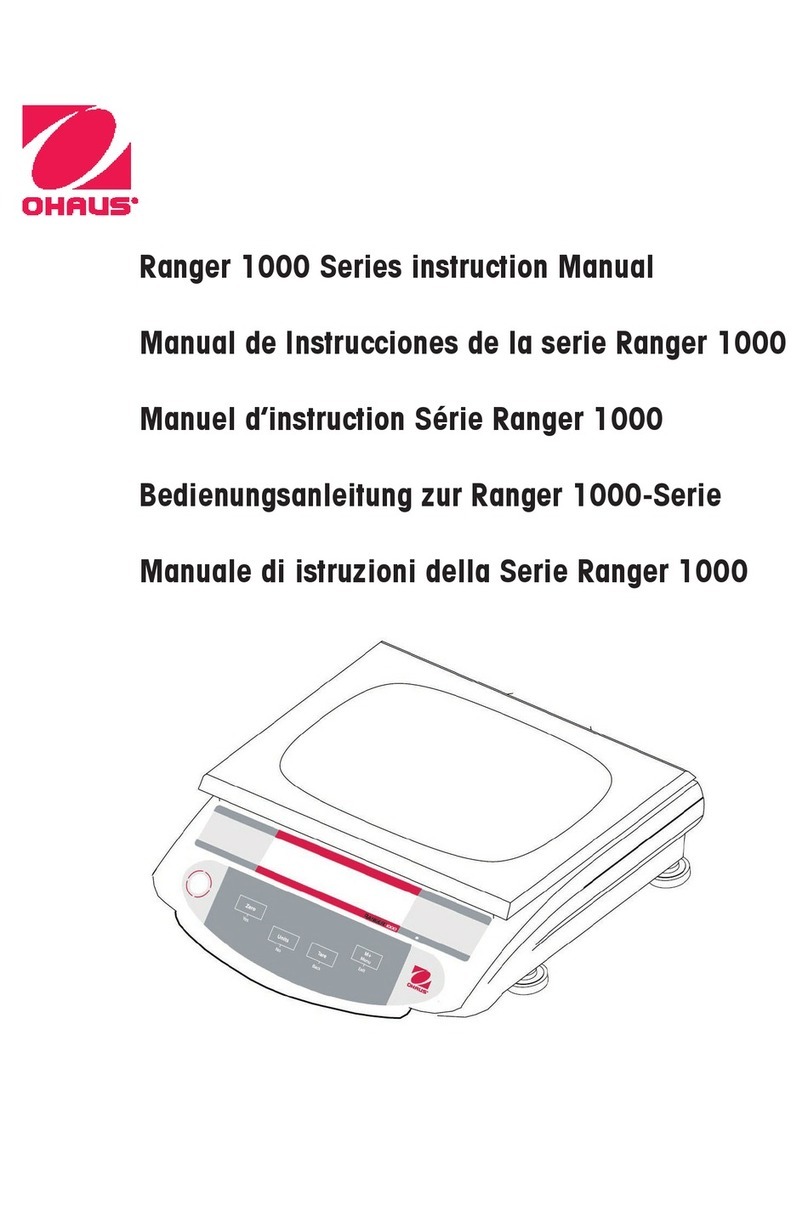
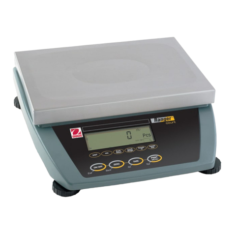
Ohaus Pioneer service ManualOhaus Pioneer service ManualOhaus Pioneer service ManualOhaus Pioneer service Manual
TABLE OF CONTENTS
Page No.
CHAPTER 1 GETTING STARTED
1.1 Introduction................................................................................................................1-1
1.2 Service Facilities........................................................................................................1-1
1.3 Tools and Test Equipment Required.........................................................................1-2
1.3.1 Special Tools......................................................................................................1-2
1.3.2 Standard Tools and Test Equipment..................................................................1-2
1.4 Specifications.............................................................................................................1-2
1.5 Balance Operation.....................................................................................................1-5
1.5.1 Overview of the Controls....................................................................................1-5
1.5.2 Overview of the Display Indicators.....................................................................1-6
1.5.3 Power On ...........................................................................................................1-7
1.5.4 Power Off ...........................................................................................................1-7
1.5.5 Menu Setup........................................................................................................1-7
1.5.6 Menu Structure...................................................................................................1-7
1.5.7 The Load Cell.....................................................................................................1-8
1.6 Connecting the RS232 Interface................................................................................1-9
1.7 RS232 Commands ..................................................................................................1-10
CHAPTER 2 TROUBLESHOOTING
2.1 Troubleshooting.........................................................................................................2-1
2.1.1 General Procedures for Troubleshooting ...........................................................2-1
2.2 Diagnostic Guide .......................................................................................................2-1
2.2.1 Diagnosis............................................................................................................2-1
2.3 Error Codes ...............................................................................................................2-4
CHAPTER 3 MAINTENANCE PROCEDURES
3.1 Preventive Maintenance............................................................................................3-1
3.1.1 Preventive Maintenance Checklist .....................................................................3-1
3.2 Opening the Balance.................................................................................................3-1
3.2.1 Variations in Opening Pioneer Models...............................................................3-2
3.3 Load Cell Removal and Disassembly........................................................................3-3
3.3.1 Variations in Pioneer Load Cells........................................................................3-3
3.3.2 Disassembly of Precision Balances with Internal Calibration.............................3-4
3.3.3 Removing Internal Calibration Weights..............................................................3-5
3.3.4 Servicing the Internal Calibration Mechanism....................................................3-5
3.3.5 Reassembling the Internal Calibration Mechanism............................................3-6
3.3.6 Disassembly of Precision Balances with InCal Mechanism ...............................3-6
3.3.7 Removing the Load Cell – Precision Balances...................................................3-7
3.3.8 Load Cell Disassembly – Precision Balances ....................................................3-8
3.3.9 Position Sensor Board Removal/Replacement/Adjustment – Precision...........3-13
3.3.10 Main Printed Circuit Board (PCB) Replacement – All Balances.......................3-14
3.3.11 Load Cell Reassembly – Precision Balances...................................................3-15
3.3.12 Removing the InCal Mechanism from InCal Analytical Balances.....................3-19
3.3.13 Removing Internal Calibration Weights and Components................................3-19
3.3.14 Re-Installing Internal Calibration Components.................................................3-21
3.3.15 Load Cell Removal/Installation – Analytical Balances......................................3-21
3.3.16 Disassembling Analytical Load Cells................................................................3-22
3.3.17 Position Sensor PC Board Removal/Replacement/Adjustment - Analytical.....3-28
3.3.18 Reassembling Analytical Load Cells ................................................................3-29
3.3.19 Block Style Load Cell Removal & Replacement...............................................3-34
Ohaus Corporation www.ohaus.com i Pioneer™ Balances Service Manual
TABLE OF CONTENTS
Page No.
3.3.20 Block Style Load Cell Disassembly & Replacement with Load Cell Kit............3-35
3.3.21 Progressive Disassembly of Block Style Load Cells ........................................3-35
3.3.22 Internal Calibration Testing ..............................................................................3-36
3.3.23 InCal Motor Removal & Replacement..............................................................3-36
3.3.24 InCal Mechanism Removal...............................................................................3-37
3.3.25 InCal Mechanism Installation ...........................................................................3-38
3.3.26 Position Sensor Assembly Removal/Installation on MFR Load Cell ................3-39
3.3.27 Removing the Block Style Load Cell from the Base Plate................................3-40
3.3.28 Installing the Block Style Load Cell on the Base Plate.....................................3-41
3.3.29 Removal and Installation of the Block Style Load Cell PC Board.....................3-42
3.3.30 Removing the Ratio Beam on Block Style Load Cells......................................3-43
3.3.31 Installing the Ratio Beam on Block Style Load Cells........................................3-47
3.3.32 Installing the InCal Weight Arm........................................................................3-49
3.3.33 Installing the Load Cell PCB-Temperature Sensor-Position Sensor................3-51
3.2.34 Setting the Up/Down Stop Screw on Block Style Load Cells ...........................3-53
CHAPTER 4 TESTING
4.1. Testing.......................................................................................................................4-1
4.1.1 Test Masses Required .......................................................................................4-2
4.2 Operational Test........................................................................................................4-1
4.3 Segment Display Test................................................................................................4-1
4.4. Performance Tests ....................................................................................................4-2
4.4.1 Precision Test.....................................................................................................4-2
4.4.2 Off-Center Load Test..........................................................................................4-3
4.4.3 Off-Center Load Adjustment for Precision Models.............................................4-4
4.4.4 Off-Center Load Adjustment for Analytical Models.............................................4-5
4.4.5 Off-Center Load Adjustment for Block Style Models..........................................4-6
4.4.6 Repeatability Test...............................................................................................4-7
4.4.7 Linearity Test......................................................................................................4-9
CHAPTER 5 DRAWINGS AND PARTS LISTS
5-1 Precision Top Load Balance Housing & Internal Parts..............................................5-2
5-2 Round Pan Block Style InCal Balance: Housing & Internal Parts..............................5-4
5-3 Square Pan Block Style Square Pan Balance: Housing & Internal Parts..................5-6
5.4 Precision Draft Shield Balance with Draft Shield: Housing & Parts...........................5-8
5.5 Analytical Balance: Housing & Internal Parts ..........................................................5-10
5.6 Precision Balance Load Cell & Parts.......................................................................5-12
5.7 Analytical Balance Load Cell & Parts ......................................................................5-14
5.8 Block Style InCal Load Cell & Parts.........................................................................5-26
Appendix A STANDARD CALIBRATION
A.1 Calibration.................................................................................................................A-1
A.1.1 Calibration Masses............................................................................................ A-1
A.2 Span Calibration....................................................................................................... A-1
A.3 Linearity Calibration.................................................................................................. A-2
Appendix B SERVICE CALIBRATION
B.1 Entering the Service Menu ....................................................................................... B-1
B.2 Ramp........................................................................................................................B-1
B.3 Service Span Calibration.......................................................................................... B-2
B.4 Service Linear Calibration......................................................................................... B-3
Pioneer™ Balances Service Manual ii Ohaus Corporation www.ohaus.com
TABLE OF CONTENTS
Page No.
APPENDIX C SOFTWARE SERVICE TOOL INSTRUCTIONS
C.1 Restore EEPROM Data............................................................................................ C-2
C.2 Replace Load Cell ....................................................................................................C-3
C.3 Install new Main Printed Circuit Board......................................................................C-4
C.4 Update Software in the Balance...............................................................................C-5
C.5 Diagnostics...............................................................................................................C-6
C.5.1Incal Weight Mechanism Testing .........................................................................C-6
LIST OF TABLES
TABLE NO. TITLE Page No.
1-1 Specifications: External Calibration Models (includes M Models).........................1-2
1-2 Specifications: Internal Calibration Models (C & CM) ...........................................1-3
1-3 Specifications: Carat Models.................................................................................1-3
1-4 Specifications: Gold Models (External Calibration)...............................................1-4
1-5 Specifications: Gold Models (Internal Calibration) ................................................1-4
1-6 Admissible Ambient Conditions.............................................................................1-5
1-7 Functions of Display Controls................................................................................1-5
1-8 Display Indicators..................................................................................................1-6
1-9 COM 1 Interface Pin Connections.........................................................................1-9
1-10 RS232 Command Table......................................................................................1-10
2-1 Diagnostic Guide...................................................................................................2-2
2-2 Error Codes...........................................................................................................2-4
4-1 Test Masses Required ..........................................................................................4-1
4-2 Tolerances – Precision Models.............................................................................4-2
4-3 Tolerances – Analytical Models.............................................................................4-2
4-4 Repeatability Worksheet .......................................................................................4-8
5-1 Precision Top Load Balance Housing & Internal Parts .........................................5-3
5-2 Round Pan Block Style InCal Balance: Housing & Internal Parts.........................5-5
5-3 Square Pan Block Style Square Pan Balance: Housing & Internal Parts..............5-7
5.4 Precision Draft Shield Balance with Draft Shield: Housing & Parts.......................5-9
5.5 Analytical Balance: Housing & Internal Parts......................................................5-11
5.6 Precision Balance Load Cell & Parts...................................................................5-13
5.7 Analytical Balance Load Cell & Parts..................................................................5-15
5.8 Block Style InCal Load Cell & Parts....................................................................5-17
LIST OF ILLUSTRATIONS
FIGURE NO. TITLE
1-1 Pioneer, Carat and Gold Series Displays..............................................................1-5
1-2 Pioneer Display Indicators.....................................................................................1-6
1-3 Pioneer Menu Structure ........................................................................................1-7
1-4 Load Cell Assembly...............................................................................................1-8
1-5 COM 1 Connector .................................................................................................1-9
1-6 Soldering points J1 and J2....................................................................................1-9
3-1 Top panel lifts up and slides out............................................................................3-2
3-2 Groove in side panel’s base liner aligns with tab on Housing...............................3-2
3-3 Precision Load Cell with Incal ...............................................................................3-3
3-4 Analytical Load Cell with Incal...............................................................................3-3
3-5 Precision Load Cell ...............................................................................................3-3
3-6 Analytical Load Cell...............................................................................................3-3
3-7 Precision Block Style Load Cell with InCal............................................................3-4
Ohaus Corporation www.ohaus.com iii Pioneer™ Balances Service Manual
TABLE OF CONTENTS
FIGURE NO. TITLE Page No.
3-8 Analytical Block Style Load Cell with InCal...........................................................3-4
3-9 Precision Balance with InCal Mechanism .............................................................3-4
3-10 InCal Weight Cover removed................................................................................3-5
3-11 Bottom Housing with Load Cell, Weight Arms and Weights removed...................3-5
3-12 InCal Motor removed from its Housing..................................................................3-6
3-13 Screws securing Weight Arm assembly................................................................3-6
3-14 Proper manner to grasp Load Cell when removing Weight Arm assembly...........3-7
3-15 Cable connects to Position Sensor Board.............................................................3-7
3-16 Access the 3 screws to release Precision balance Load Cell from top center......3-7
3-17 Service Fixture, screws and washers for 150g to 310g Precision balances .........3-8
3-18 Service Fixture, screws and washers for 510g to 4100g Precision balances .......3-8
3-19 Precision Load Cell top .........................................................................................3-8
3-20 Precision Load Cell bottom ...................................................................................3-8
3-21 Precision Load Cell (150g to 310g) top, with Service Fixture attached.................3-9
3-22 Service Fixture for 510g to 4100g Precision Load Cell, attached to Hanger.........3-9
3-23 Bent Flexure..........................................................................................................3-9
3-24 Position Sensor Board.........................................................................................3-10
3-25 Contact Board with ribbon cable .........................................................................3-10
3-26 Fine wires connected to the Contact Board, and affixed to Ratio Beam.............3-10
3-27 Contact Board taped to Ratio Beam after removal from frame...........................3-11
3-28 Hanger ................................................................................................................3-10
3-29 Two screws secure Magnet Half.........................................................................3-11
3-30 Sideways Motion Stop Plate................................................................................3-11
3-31 Ratio Beam clearing stop on Up/Down Stop Screw as it is lifted out..................3-12
3-32 Magnets must be clean.......................................................................................3-12
3-33 Position Sensor Board.........................................................................................3-13
3-34 Adjust position of Sensor Board until Err8.X does not appear............................3-13
3-35 Position Sensor Board.........................................................................................3-14
3-36 Installing Ratio Beam, clearing the Up/down Stop Screw...................................3-15
3-37 Precision Load Cell (150g to 310g) top, with Service Fixture attached...............3-15
3-38 Service Fixture for 510g to 4100g Precision Load Cell, attached to Hanger.......3-15
3-39 Sideways Motion Stop Plate................................................................................3-16
3-40 Two screws secure Magnet Half.........................................................................3-16
3-41 Contact Board .....................................................................................................3-16
3-42 Solder points on Position Sensor Board..............................................................3-16
3-43 Precision Load Cell top .......................................................................................3-17
3-44 Precision Load Cell bottom .................................................................................3-17
3-45 Ratio Beam Flexures and Vertical Flexure..........................................................3-17
3-46 Insert the 3 screws to secure Precision Load Cell in Bottom Housing................3-17
3-47 When Position Sensor Board shows normal weight, tighten its screws..............3-18
3-48 Analytical Balance with InCal Mechanism...........................................................3-19
3-49 InCal Weight Covers removed ............................................................................3-19
3-50 Bottom Housing with Load Cell, Weight Arms and Weights removed.................3-20
3-51 InCal Motor removed from its assembly..............................................................3-20
3-52 InCal Motor Cam in correct position for reassembly ...........................................3-20
3-53 Cable connects to the Position Sensor Board.....................................................3-21
3-54 On Analytical balances, the 3 screws securing Load Cell are on bottom............3-21
3-55 Service Fixture, screws and shims for Analytical balances.................................3-22
3-56 Bottom Mounting Plate and Flexure Arms, Analytical balance’s Load Cell.........3-22
3-57 Top Mounting Plate and Flexure Arms, Analytical balance’s Load Cell..............3-22
Pioneer™ Balances Service Manual iv Ohaus Corporation www.ohaus.com
TABLE OF CONTENTS
LIST OF ILLUSTRATIONS
FIGURE NO. TITLE Page No.
3-58 Screws removed from Bottom Mounting Plate inserted into the Hanger.............3-23
3-59 Shims are inserted between the Hanger and the Load Cell................................3-23
3-60 Analytical balance Load Cell with Top Bracket visible ........................................3-23
3-61 Vertical Flexure and screws, Lock Plate, washers, and bushings, removed.......3-23
3-62 Top Flexure Arm (Analytical)...............................................................................3-23
3-63 Bottom Flexure Arm (Analytical)..........................................................................3-23
3-64 Hanger with two screws ......................................................................................3-25
3-65 Service Fixture attached to the front of Load Cell after removing Hanger ..........3-25
3-66 The Vane is secured by two screws near the rear of the Load Cell....................3-25
3-67 The Vane removed..............................................................................................3-25
3-68 Two solder points on PSB, and two screw holes for removing the board...........3-26
3-69 Contact Board with 3-wire ribbon cable soldered to it.........................................3-26
3-70 Four screws secure the Magnet Half to the Ratio Beam.....................................3-26
3-71 The Magnet Half, when removed, should be cleaned.........................................3-25
3-72 A screw connects the Contact Board to the Load Cell........................................3-26
3-73 Use a smaller screw to temporarily fasten it to the Ratio Beam..........................3-26
3-74 The Sideways Motion Stop Plate and the black Up/Down Stop screw ...............3-27
3-75 Position Sensor Board (Analytical)......................................................................3-28
3-76 Adjust Position Sensor Board vertically until Err8.X does not appear.................3-28
3-77 The Ratio Beam needs to clear the groove in the Up/Down Stop Screw............3-29
3-78 Service Fixture is installed prior to installing Ratio Beam Flexures.....................3-29
3-79 Sideways Motion Stop Plate and Up/Down Stop Screw .....................................3-29
3-80 Elongated holes on Ratio Beam Flexures go on the bottom...............................3-29
3-81 Installing the Magnet Half....................................................................................3-30
3-82 Four screws on Magnet Half ...............................................................................3-30
3-83 Position Sensor Board.........................................................................................3-30
3-84 3-wire cable soldered to Contact Board..............................................................3-30
3-85 Installing the Vane...............................................................................................3-30
3-86 Screws removed from Bottom Mounting Plate inserted into the Hanger.............3-31
3-87 Insert shims between the Hanger and the Load Cell on both sides....................3-31
3-88 Bottom Flexure Arm ............................................................................................3-31
3-89 Top Flexure Arm..................................................................................................3-31
3-90 Vertical Flexure ...................................................................................................3-31
3-91 Vertical Flexure and screws, Lock Plate, washers, and bushings, removed.......3-31
3-92 Analytical InCal Load Cell with Top Bracket visible.............................................3-32
3-93 Analytical balance Load Cell with Top Bracket visible ........................................3-32
3-94 Bottom Mounting Plate on Analytical Load Cell ..................................................3-32
3-95 Ribbon cable connects PSB to Main PCB...........................................................3-32
3-96 When Position Sensor Board shows normal weight, tighten its screws..............3-33
3-97 Block Style Load Cell ..........................................................................................3-34
3-98 Service Toolset for Block Style Load Cells. PN 476000-030 .............................3-35
3-99 InCal Motor..........................................................................................................3-36
3-100 InCal Motor Removal...........................................................................................3-36
3-101 Motor Coupler .....................................................................................................3-36
3-102 Motor Shaft in counter-clockwise position...........................................................3-37
3-103 Mounting Screws holding InCal Mechanism .......................................................3-37
3-104 Removing the InCal Mechanism .........................................................................3-37
3-105 InCal Mechanism Alignment................................................................................3-38
3-106 Centering InCal Weight.......................................................................................3-38
Ohaus Corporation www.ohaus.com v Pioneer™ Balances Service Manual
TABLE OF CONTENTS
LIST OF ILLUSTRATIONS
FIGURE NO. TITLE Page No.
3-107 Removing Position Sensor..................................................................................3-39
3-108 Ratio Beam Pin Alignment ..................................................................................3-39
3-109 Base Plate Removal............................................................................................3-40
3-110 Load Cell Mounting Components........................................................................3-41
3-111 Load Cell Alignment to Base Plate......................................................................3-41
3-112 Block Style Load Cell PC Board Item Locations .................................................3-42
3-113 Block Style Load Cell PC Board Removed from Load Cell.................................3-42
3-114 Load Cell PCB-Temperature Sensor-Position Sensor assembly........................3-43
3-115 Position Sensor...................................................................................................3-43
3-116 Removing Temperature Sensor..........................................................................3-43
3-117 Load Cell PCB.....................................................................................................3-44
3-118 Contact Board Cover is removed by squeezing the plastic post.........................3-44
3-119 Contact Board with cover holder off....................................................................3-44
3-120 Centering Pins.....................................................................................................3-44
3-121 Centering Pins Installed ......................................................................................3-44
3-122 Contact Board Location.......................................................................................3-45
3-123 Contact Board with cover holder off....................................................................3-45
3-124 Loosening Ratio Beam Nuts................................................................................3-45
3-125 Ratio Beam Screws and Washers removed........................................................3-45
3-126 Loosening InCal Weight Arm nuts.......................................................................3-46
3-127 Weight Arm Screws and Washers removed........................................................3-46
3-128 InCal Weight Arm removal ..................................................................................3-46
3-129 InCal Weight Arm removed.................................................................................3-46
3-130 Aluminum Sleeves removed................................................................................3-47
3-131 Up/Down Stop Screw..........................................................................................3-47
3-132 Centering Pins removed......................................................................................3-47
3-133 Removing the Ratio Beam ..................................................................................3-47
3-134 Ratio Beam Removed.........................................................................................3-47
3-135 Removing the Ratio Beam ..................................................................................3-47
3-136 Ratio Beam Removed.........................................................................................3-47
3-137 Removing the Aluminum Sleeves .......................................................................3-47
3-138 Ratio Beam Weight Removal..............................................................................3-48
3-139 Load Cell Critical Area.........................................................................................3-48
3-140 Magnet Area........................................................................................................3-48
3-141 Ratio Beam Vane Slotted Area ...........................................................................3-49
3-142 Four Ratio Beam sleeves are larger than the four Weight Arm sleeves .............3-49
3-143 Replacing the Ratio Beam...................................................................................3-49
3-144 Positioning the Ratio Beam over the Magnet......................................................3-49
3-145 Centering Pin goes into first hole after upward bend in Ratio Beam...................3-49
3-146 InCal Weight Arm before insertion ......................................................................3-50
3-147 Inserting InCal Weight Arm .................................................................................3-50
3-148 Weight Arm must be lifted slightly to insert Centering Pin...................................3-50
3-149 Proper method for tightening nuts while holding screw head stationary.............3-50
3-150 Centering pins in Ratio Beam..............................................................................3-51
3-151 Tightening Ratio Beam nuts................................................................................3-51
3-152 Up/Down Stop Screw..........................................................................................3-51
3-153 Repositioning the Contact Board and Screw.......................................................3-51
3-154 Load Cell PCB, Temperature Sensor and Position Sensor.................................3-52
3-155 Groove on left of PCB fits tab on Load Cell frame ..............................................3-52
Pioneer™ Balances Service Manual vi Ohaus Corporation www.ohaus.com

TABLE OF CONTENTS
LIST OF ILLUSTRATIONS
FIGURE NO. TITLE Page No.
3-156 Temperature Sensor extends into a hole in the Magnet .....................................3-52
3-157 Position Sensor on the Magnet...........................................................................3-53
3-158 Pin centered in PSB............................................................................................3-53
3-159 Load Cell PCB Test Connector...........................................................................3-54
3-160 Test Connector Detail..........................................................................................3-54
3-161 Up/Down Stop Screw..........................................................................................3-54
4-1 Segment Display...................................................................................................4-1
4-2 Mass Placement Locations for Off-Center Load Test ...........................................4-3
4-3 Off-Center Load Adjustment Screws on Analytical models...................................4-4
4-4 Off-Center Load Adjustment Screws on Precision models ...................................4-4
4-5 Off-Center Load Adjustments................................................................................4-4
5-1 Precision Top Load Balance Housing & Internal Parts..............................................5-2
5-2 Round Pan Block Style InCal Balance: Housing & Internal Parts..............................5-4
5-3 Square Pan Block Style Square Pan Balance: Housing & Internal Parts..................5-6
5.4 Precision Draft Shield Balance with Draft Shield: Housing & Parts...........................5-8
5.5 Analytical Balance: Housing & Internal Parts ..........................................................5-10
5.6 Precision Balance Load Cell & Parts.......................................................................5-12
5.7 Analytical Balance Load Cell & Parts ......................................................................5-14
5.8 Block Style InCal Load Cell & Parts.........................................................................5-26
C-1 Com Port Configuration Menu..............................................................................C-1
C-2 The Software Service Tool’s Restore EEProm Tab.............................................C-2
C-3 The Software Service Tool’s Replace Load Cell Tab...........................................C-3
C-4 The Software Service Tool’s Replace PCB Tab...................................................C-4
C-5 The Software Service Tool’s Download Software Tab.........................................C-5
C-6 The Software Service Tool’s Diagnostics Tab......................................................C-6
Ohaus Corporation www.ohaus.com vii Pioneer™ Balances Service Manual
This is a “Table of Contents preview” for quality assurance
The full manual can be found at http://the-checkout-tech.com/estore/catalog/
We also offer free downloads, a free keyboard layout designer, cable diagrams, free help and
support.
http://the-checkout-tech.com : the biggest supplier of cash register and scale manuals on the net

Other manuals for Pioneer

3

Other OHAUS Scale manuals

OHAUS CS 2000 User manual

OHAUS

OHAUS CS 2000 User manual

OHAUS Ranger User manual

OHAUS

OHAUS Ranger User manual

OHAUS PR Series User manual

OHAUS

OHAUS PR Series User manual

OHAUS D31P75SD User manual

OHAUS

OHAUS D31P75SD User manual

OHAUS Adventurer Pro Series User manual

OHAUS

OHAUS Adventurer Pro Series User manual

OHAUS Valor V31XH202 User manual

OHAUS

OHAUS Valor V31XH202 User manual

OHAUS Defender 3000 Series User manual

OHAUS

OHAUS Defender 3000 Series User manual

OHAUS PX Series User manual

OHAUS

OHAUS PX Series User manual

OHAUS Adventurer series User manual

OHAUS

OHAUS Adventurer series User manual

OHAUS Navigator NV212 User manual

OHAUS

OHAUS Navigator NV212 User manual

OHAUS SD75L User manual

OHAUS

OHAUS SD75L User manual

OHAUS Scout SKX Series User manual

OHAUS

OHAUS Scout SKX Series User manual

OHAUS EX124 User manual

OHAUS

OHAUS EX124 User manual

OHAUS ES series User manual

OHAUS

OHAUS ES series User manual

OHAUS Valor 1000 User manual

OHAUS

OHAUS Valor 1000 User manual

OHAUS CS Series User manual

OHAUS

OHAUS CS Series User manual

OHAUS Scout STX Series User manual

OHAUS

OHAUS Scout STX Series User manual

OHAUS Defender 2000 User manual

OHAUS

OHAUS Defender 2000 User manual

OHAUS Defender 6000 Indicators User manual

OHAUS

OHAUS Defender 6000 Indicators User manual

OHAUS Aviator 2000 Series User manual

OHAUS

OHAUS Aviator 2000 Series User manual

OHAUS Ranger 7000 R71MHD3 User manual

OHAUS

OHAUS Ranger 7000 R71MHD3 User manual

OHAUS Pioneer User manual

OHAUS

OHAUS Pioneer User manual

OHAUS Defender D30BR User manual

OHAUS

OHAUS Defender D30BR User manual

OHAUS 4000W Series User manual

OHAUS

OHAUS 4000W Series User manual

Popular Scale manuals by other brands

Seca 701 Instruction manual and guarantee

Seca

Seca 701 Instruction manual and guarantee

SHEKEL Healthweigh H611 Service manual

SHEKEL

SHEKEL Healthweigh H611 Service manual

Salter 1036 Instructions and guarantee

Salter

Salter 1036 Instructions and guarantee

Health O Meter 2210KL User instruction

Health O Meter

Health O Meter 2210KL User instruction

Withings Body Cardio Installation and operating instructions

Withings

Withings Body Cardio Installation and operating instructions

Gima BABY manual

Gima

Gima BABY manual

FAR BDC5SIL CI instruction manual

FAR

FAR BDC5SIL CI instruction manual

Steinberg Systems SBS-TW-3C user manual

Steinberg Systems

Steinberg Systems SBS-TW-3C user manual

Magnescale SR87 installation manual

Magnescale

Magnescale SR87 installation manual

Nagata TABLE TOP SCALE FAT-06 user manual

Nagata

Nagata TABLE TOP SCALE FAT-06 user manual

Bestron DEK4150 instruction manual

Bestron

Bestron DEK4150 instruction manual

Vetek VRB-20 user manual

Vetek

Vetek VRB-20 user manual

Minebea Intec ISEDE-16-34-64-H operating manual

Minebea Intec

Minebea Intec ISEDE-16-34-64-H operating manual

Lumme LU-SC1360 user manual

Lumme

Lumme LU-SC1360 user manual

Dualit 5Kg Kitchen scales Instruction manual & guarantee

Dualit

Dualit 5Kg Kitchen scales Instruction manual & guarantee

Valor V71P3T-M instruction manual

Valor

Valor V71P3T-M instruction manual

Propert bodysense Food Monitor 10000 instruction manual

Propert

Propert bodysense Food Monitor 10000 instruction manual

KERN CM 150-1 operating instructions

KERN

KERN CM 150-1 operating instructions

manuals.online logo
manuals.online logoBrands
  • About & Mission
  • Contact us
  • Privacy Policy
  • Terms and Conditions

Copyright 2025 Manuals.Online. All Rights Reserved.