==========================
SUPERBOARD
II
ONLY
==========================
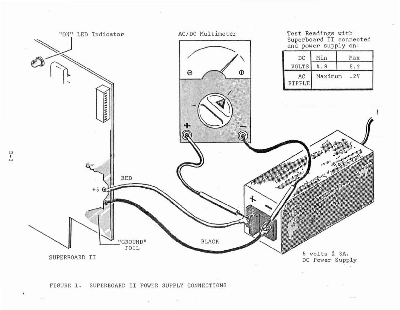
1.
Consult
Figure
1,
Superboard
II
power
supply
connections.
The
power
supply
MUST
BE
a 5
volt
@
3A
(minimum)
regulated
supply
(+
5\
maximum
ripple).
No
other
supply
will
be
adequate~
You'll
also
need
an
AC/DC
multimeter.
2.
Choose
a
work
area
which
is
free
of
all
foreign
matter,
paper
clips,
or
any
other
conductive
materials.
The
computer
or
power
supply
could
be
damaged
if
these
come
in
contact
with
the
foils
on
the
board.
3.
Observe
that
the
Superboard
II
should
not
be
treated
roughly,
flexed,
bent,
or
otherwise
abused.
4.
Make
sure
the
power
supply
is
not
plugged
in.
5.
Connect
the
RED
and
BLACK
wires
from
the
Superboard
II
to
the
+
and
-
terminals.
6.
Set
the
AC/DC
multimeter
to
a
DC
you
measure
5
volts
accurately.
or
0-10
volts
is
adequate.)
voltage
range
to
(A
range
of
0-
5)
let
0-6,
7
..
Next,
you
will
observe
the
"ON"
LED
indicator
on
the
Superboard
II,
and
the
power
supply's
voltage
under
load.
Briefly
turn
on
the
power
supply
and
observe
that
the
"ON"
LED
glows.
If
not,
turn
off
the
supply
immediately
and
check
your
power
supply
leads.
They
may
be
reversed.
Go
back
to
Step
1.
8.
Again,
turn
on
the
power
supply
and
measure
the
DC
voltage.
It
must
be
between
4.8
and
5.2
volts.
A
reading
less
than
4.8
indicates
that
the
power
supply
probably
lacks
the
required
voltage
or
current
capability.
A
power
supply
delivering
more
than
5.2
volts
may
damage
the
computer.
Turn
off
the
power
supply.
9.
Set
the
multimete~·to
measure
a
voltage
of
about
0.5
volts
AC
(probably
the
lowest
AC
range).
10.
Turn
on
the
power
supply
and
measure
the
AC
voltage.
This
represents
ripple
and
must
not
exceed
0.2
volts
AC.
11.
If
everything
checks
out,
proceed
to
the
video
display
hook-up.
B-4